Quick Installation Guide
Page 4
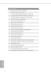
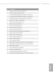
... Power Connector (ATXPWR1) 7 USB 3.2 Gen1 Header (USB3_5_6) 8 SATA3 Connector (SATA3_2) 9 SATA3 Connector (SATA3_3) 10 SATA3 Connector (SATA3_5) 11 SATA3 Connector (SATA3_4) 12 Chassis Intrusion and Speaker Header (SPK_CI1) 13 System Panel Header (PANEL1) 14 SATA3 Connector (SATA3_0) 15 SATA3 Connector (SATA3_1) 16 USB 2.0 Header (USB5_6) 17 USB 2.0 Header (USB3_4) 18 Chassis...
... Power Connector (ATXPWR1) 7 USB 3.2 Gen1 Header (USB3_5_6) 8 SATA3 Connector (SATA3_2) 9 SATA3 Connector (SATA3_3) 10 SATA3 Connector (SATA3_5) 11 SATA3 Connector (SATA3_4) 12 Chassis Intrusion and Speaker Header (SPK_CI1) 13 System Panel Header (PANEL1) 14 SATA3 Connector (SATA3_0) 15 SATA3 Connector (SATA3_1) 16 USB 2.0 Header (USB5_6) 17 USB 2.0 Header (USB3_4) 18 Chassis...
Quick Installation Guide
Page 5
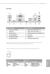
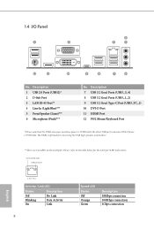
Description 1 USB 2.0 Ports (USB12)* 2 D-Sub Port 3 LAN RJ-45 Port** 4 Line In (Light Blue)*** 5 Front Speaker (Lime)*** 6 Microphone (Pink)*** No. The USB1 is optimal for the LAN port LED indications. I/O Panel 1 2 B365M Pro4-F 4 3 5 12 11 10 9 8 7 6 No. ACT/LINK LED SPEED LED LAN Port Activity / Link LED Status Off Blinking On Description No Link... USB1 consumes auxiliary power (+5VSB) while the other USB ports consume DUAL Power (+5VDUAL). Please refer to the table below for connecting the USB Type speaker and headset. ** There are two LEDs on the LAN port.
Description 1 USB 2.0 Ports (USB12)* 2 D-Sub Port 3 LAN RJ-45 Port** 4 Line In (Light Blue)*** 5 Front Speaker (Lime)*** 6 Microphone (Pink)*** No. The USB1 is optimal for the LAN port LED indications. I/O Panel 1 2 B365M Pro4-F 4 3 5 12 11 10 9 8 7 6 No. ACT/LINK LED SPEED LED LAN Port Activity / Link LED Status Off Blinking On Description No Link... USB1 consumes auxiliary power (+5VSB) while the other USB ports consume DUAL Power (+5VDUAL). Please refer to the table below for connecting the USB Type speaker and headset. ** There are two LEDs on the LAN port.
Quick Installation Guide
Page 6
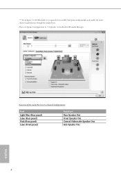
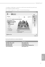
*** To configure 7.1 CH HD Audio, it is required to "7.1 Speaker"in 7.1-channel Configuration: Port Light Blue (Rear panel) Lime (Rear panel) Pink (Rear panel) Lime (Front panel) Function Rear Speaker Out Front Speaker Out Central /Subwoofer Speaker Out Side Speaker Out 4 English Function of the Audio Ports in the Realtek HD Audio Manager. Please set Speaker Configuration to use an HD front panel audio module and enable the multichannel audio feature through the audio driver.
*** To configure 7.1 CH HD Audio, it is required to "7.1 Speaker"in 7.1-channel Configuration: Port Light Blue (Rear panel) Lime (Rear panel) Pink (Rear panel) Lime (Front panel) Function Rear Speaker Out Front Speaker Out Central /Subwoofer Speaker Out Side Speaker Out 4 English Function of the Audio Ports in the Realtek HD Audio Manager. Please set Speaker Configuration to use an HD front panel audio module and enable the multichannel audio feature through the audio driver.

Quick Installation Guide
Page 10
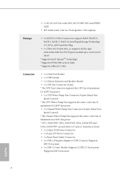
• 1 x RJ-45 LAN Port with LED (ACT/LINK LED and SPEED LED) • HD Audio Jacks: Line in / Front Speaker / Microphone Storage • 6 x SATA3 6.0 Gb/s Connectors, support RAID (RAID 0, RAID 1, RAID 5, RAID 10, Intel Rapid Storage Technology 17), NCQ, AHCI and Hot Plug...Gen3 x4 (32 Gb/s)* * Supports Intel® OptaneTM Technology * Supports NVMe SSD as boot disks * Supports ASRock U.2 Kit Connector • 1 x COM Port Header • 1 x TPM Header • 1 x Chassis Intrusion and Speaker Header • 1 x CPU Fan Connector (4-pin) * The CPU Fan Connector supports the CPU fan of ...
• 1 x RJ-45 LAN Port with LED (ACT/LINK LED and SPEED LED) • HD Audio Jacks: Line in / Front Speaker / Microphone Storage • 6 x SATA3 6.0 Gb/s Connectors, support RAID (RAID 0, RAID 1, RAID 5, RAID 10, Intel Rapid Storage Technology 17), NCQ, AHCI and Hot Plug...Gen3 x4 (32 Gb/s)* * Supports Intel® OptaneTM Technology * Supports NVMe SSD as boot disks * Supports ASRock U.2 Kit Connector • 1 x COM Port Header • 1 x TPM Header • 1 x Chassis Intrusion and Speaker Header • 1 x CPU Fan Connector (4-pin) * The CPU Fan Connector supports the CPU fan of ...
Quick Installation Guide
Page 21
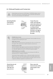
...sleep state. When connecting your system using the power switch. Note the positive and negative pins before connecting the cables. English Chassis Intrusion and Speaker Header (7-pin SPK_CI1) (see p.1, No. 13) PLED+ PLEDPWRBTN# GND 1 GND RESET# GND HDLEDHDLED+ Connect the power switch, reset ... the pin assignments below. PLED (System Power LED): Connect to the motherboard. The LED is reading or writing data. B365M Pro4-F 2.6 Onboard Headers and Connectors Onboard headers and connectors are matched correctly. Placing jumper caps over these headers and connectors.
...sleep state. When connecting your system using the power switch. Note the positive and negative pins before connecting the cables. English Chassis Intrusion and Speaker Header (7-pin SPK_CI1) (see p.1, No. 13) PLED+ PLEDPWRBTN# GND 1 GND RESET# GND HDLEDHDLED+ Connect the power switch, reset ... the pin assignments below. PLED (System Power LED): Connect to the motherboard. The LED is reading or writing data. B365M Pro4-F 2.6 Onboard Headers and Connectors Onboard headers and connectors are matched correctly. Placing jumper caps over these headers and connectors.
User Manual
Page 10
• 1 x RJ-45 LAN Port with LED (ACT/LINK LED and SPEED LED) • HD Audio Jacks: Line in / Front Speaker / Microphone Storage • 6 x SATA3 6.0 Gb/s Connectors, support RAID (RAID 0, RAID 1, RAID 5, RAID 10, Intel Rapid Storage Technology 17), NCQ, AHCI and Hot Plug...Gen3 x4 (32 Gb/s)* * Supports Intel® OptaneTM Technology * Supports NVMe SSD as boot disks * Supports ASRock U.2 Kit Connector • 1 x COM Port Header • 1 x TPM Header • 1 x Chassis Intrusion and Speaker Header • 1 x CPU Fan Connector (4-pin) * The CPU Fan Connector supports the CPU fan of ...
• 1 x RJ-45 LAN Port with LED (ACT/LINK LED and SPEED LED) • HD Audio Jacks: Line in / Front Speaker / Microphone Storage • 6 x SATA3 6.0 Gb/s Connectors, support RAID (RAID 0, RAID 1, RAID 5, RAID 10, Intel Rapid Storage Technology 17), NCQ, AHCI and Hot Plug...Gen3 x4 (32 Gb/s)* * Supports Intel® OptaneTM Technology * Supports NVMe SSD as boot disks * Supports ASRock U.2 Kit Connector • 1 x COM Port Header • 1 x TPM Header • 1 x Chassis Intrusion and Speaker Header • 1 x CPU Fan Connector (4-pin) * The CPU Fan Connector supports the CPU fan of ...
User Manual
Page 13
... Power Connector (ATXPWR1) 7 USB 3.2 Gen1 Header (USB3_5_6) 8 SATA3 Connector (SATA3_2) 9 SATA3 Connector (SATA3_3) 10 SATA3 Connector (SATA3_5) 11 SATA3 Connector (SATA3_4) 12 Chassis Intrusion and Speaker Header (SPK_CI1) 13 System Panel Header (PANEL1) 14 SATA3 Connector (SATA3_0) 15 SATA3 Connector (SATA3_1) 16 USB 2.0 Header (USB5_6) 17 USB 2.0 Header (USB3_4) 18 Chassis... (TPMS1) 21 Clear CMOS Jumper (CLRMOS1) 22 COM Port Header (COM1) 23 Front Panel Audio Header (HD_AUDIO1) 24 Chassis/Water Pump Fan Connector (CHA_FAN1/WP) B365M Pro4-F English 7
... Power Connector (ATXPWR1) 7 USB 3.2 Gen1 Header (USB3_5_6) 8 SATA3 Connector (SATA3_2) 9 SATA3 Connector (SATA3_3) 10 SATA3 Connector (SATA3_5) 11 SATA3 Connector (SATA3_4) 12 Chassis Intrusion and Speaker Header (SPK_CI1) 13 System Panel Header (PANEL1) 14 SATA3 Connector (SATA3_0) 15 SATA3 Connector (SATA3_1) 16 USB 2.0 Header (USB5_6) 17 USB 2.0 Header (USB3_4) 18 Chassis... (TPMS1) 21 Clear CMOS Jumper (CLRMOS1) 22 COM Port Header (COM1) 23 Front Panel Audio Header (HD_AUDIO1) 24 Chassis/Water Pump Fan Connector (CHA_FAN1/WP) B365M Pro4-F English 7
User Manual
Page 14
... connection 1Gbps connection English The USB1 is optimal for the LAN port LED indications. Please refer to the table below for connecting the USB Type speaker and headset. ** There are two LEDs on the LAN port. Description 7 USB 3.2 Gen1 Ports (USB3_3_4) 8 USB 3.2 Gen1 Ports (USB3_1_2) 9 USB 3.2 Gen1 Type-C Port (USB3_TC_1)...) while the other USB ports consume DUAL Power (+5VDUAL). Description 1 USB 2.0 Ports (USB12)* 2 D-Sub Port 3 LAN RJ-45 Port** 4 Line In (Light Blue)*** 5 Front Speaker (Lime)*** 6 Microphone (Pink)*** No. 1.4 I/O Panel 1 2 4 3 5 12 11 10 9 8 7 6 No.
... connection 1Gbps connection English The USB1 is optimal for the LAN port LED indications. Please refer to the table below for connecting the USB Type speaker and headset. ** There are two LEDs on the LAN port. Description 7 USB 3.2 Gen1 Ports (USB3_3_4) 8 USB 3.2 Gen1 Ports (USB3_1_2) 9 USB 3.2 Gen1 Type-C Port (USB3_TC_1)...) while the other USB ports consume DUAL Power (+5VDUAL). Description 1 USB 2.0 Ports (USB12)* 2 D-Sub Port 3 LAN RJ-45 Port** 4 Line In (Light Blue)*** 5 Front Speaker (Lime)*** 6 Microphone (Pink)*** No. 1.4 I/O Panel 1 2 4 3 5 12 11 10 9 8 7 6 No.
User Manual
Page 15
Please set Speaker Configuration to use an HD front panel audio module and enable the multichannel audio feature through the audio driver. B365M Pro4-F *** To configure 7.1 CH HD Audio, it is required to "7.1 Speaker"in 7.1-channel Configuration: Port Light Blue (Rear panel) Lime (Rear panel) Pink (Rear panel) Lime (Front panel) Function Rear Speaker Out Front Speaker Out Central /Subwoofer Speaker Out Side Speaker Out 9 English Function of the Audio Ports in the Realtek HD Audio Manager.
Please set Speaker Configuration to use an HD front panel audio module and enable the multichannel audio feature through the audio driver. B365M Pro4-F *** To configure 7.1 CH HD Audio, it is required to "7.1 Speaker"in 7.1-channel Configuration: Port Light Blue (Rear panel) Lime (Rear panel) Pink (Rear panel) Lime (Front panel) Function Rear Speaker Out Front Speaker Out Central /Subwoofer Speaker Out Side Speaker Out 9 English Function of the Audio Ports in the Realtek HD Audio Manager.

User Manual
Page 25
B365M Pro4-F 2.6 Onboard Headers and Connectors Onboard headers and connectors are matched correctly. Placing ...way to turn off when the system is off your chassis front panel module to the motherboard. English Chassis Intrusion and Speaker Header (7-pin SPK_CI1) (see p.6, No. 13) PLED+ PLEDPWRBTN# GND 1 GND RESET# GND HDLEDHDLED+ Connect the ...is operating. A front panel module mainly consists of power switch, reset switch, power LED, hard drive activity LED, speaker and etc. RESET (Reset Switch): Connect to perform a normal restart. Do NOT place jumper caps over the headers...
B365M Pro4-F 2.6 Onboard Headers and Connectors Onboard headers and connectors are matched correctly. Placing ...way to turn off when the system is off your chassis front panel module to the motherboard. English Chassis Intrusion and Speaker Header (7-pin SPK_CI1) (see p.6, No. 13) PLED+ PLEDPWRBTN# GND 1 GND RESET# GND HDLEDHDLED+ Connect the ...is operating. A front panel module mainly consists of power switch, reset switch, power LED, hard drive activity LED, speaker and etc. RESET (Reset Switch): Connect to perform a normal restart. Do NOT place jumper caps over the headers...
