

User Manual
Page 4
... Contents 1 1.2 Specifications 2 1.3 Motherboard Layout 6 1.4 I/O Panel 8 Chapter 2 Installation 10 2.1 Installing the CPU 11 2.2 Installing the CPU Fan and Heatsink 14 2.3 Installing Memory Modules (DIMM) 15 2.4 Expansion Slots (PCI Express Slots) 17 2.5 Jumpers Setup 18 2.6 Onboard Headers and Connectors 19 Chapter 3 Software and Utilities Operation 27 3.1 Installing Drivers 27 3.2 A-Tuning 28 3.3 ASRock Live Update & APP Shop 31 3.3.1 UI Overview 31 3.3.2 Apps 32 3.3.3 BIOS & Drivers 35 3.3.4 Setting 36 Chapter 4 UEFI SETUP UTILITY 37 4.1 Introduction...
... Contents 1 1.2 Specifications 2 1.3 Motherboard Layout 6 1.4 I/O Panel 8 Chapter 2 Installation 10 2.1 Installing the CPU 11 2.2 Installing the CPU Fan and Heatsink 14 2.3 Installing Memory Modules (DIMM) 15 2.4 Expansion Slots (PCI Express Slots) 17 2.5 Jumpers Setup 18 2.6 Onboard Headers and Connectors 19 Chapter 3 Software and Utilities Operation 27 3.1 Installing Drivers 27 3.2 A-Tuning 28 3.3 ASRock Live Update & APP Shop 31 3.3.1 UI Overview 31 3.3.2 Apps 32 3.3.3 BIOS & Drivers 35 3.3.4 Setting 36 Chapter 4 UEFI SETUP UTILITY 37 4.1 Introduction...
User Manual
Page 6
...-HDV Motherboard (Micro ATX Form Factor) • ASRock B360M-HDV Quick Installation Guide • ASRock B360M-HDV Support CD • 1 x I/O Panel Shield • 2 x Serial ATA (SATA) Data Cables (Optional) • 1 x Screw for purchasing ASRock B360M-HDV motherboard, a reliable motherboard produced under ASRock's consistently stringent quality control. You may find the latest VGA cards and CPU support list on ASRock's website without notice. Chapter 3 contains the operation guide of the BIOS setup. Chapter 4 contains the configuration guide of the software and utilities. In case...
...-HDV Motherboard (Micro ATX Form Factor) • ASRock B360M-HDV Quick Installation Guide • ASRock B360M-HDV Support CD • 1 x I/O Panel Shield • 2 x Serial ATA (SATA) Data Cables (Optional) • 1 x Screw for purchasing ASRock B360M-HDV motherboard, a reliable motherboard produced under ASRock's consistently stringent quality control. You may find the latest VGA cards and CPU support list on ASRock's website without notice. Chapter 3 contains the operation guide of the BIOS setup. Chapter 4 contains the configuration guide of the software and utilities. In case...
User Manual
Page 8
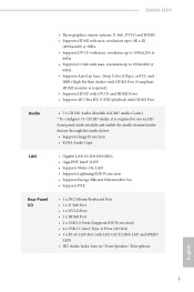
... • Supports PXE Rear Panel I/O • 1 x PS/2 Mouse/Keyboard Port • 1 x D-Sub Port • 1 x DVI-D Port • 1 x HDMI Port • 2 x USB 2.0 Ports (Supports ESD Protection) • 4 x USB 3.1 Gen2 Type-A Ports (10 Gb/s) • 1 x RJ-45 LAN Port with max. resolution up to 1920x1200 @ 60Hz • Supports D-Sub with LED (ACT/LINK LED and SPEED LED) • HD Audio Jacks: Line in / Front Speaker / Microphone English 3 B360M-HDV • Three graphics output options: D-Sub, DVI-D and HDMI • Supports HDMI with max. resolution...
... • Supports PXE Rear Panel I/O • 1 x PS/2 Mouse/Keyboard Port • 1 x D-Sub Port • 1 x DVI-D Port • 1 x HDMI Port • 2 x USB 2.0 Ports (Supports ESD Protection) • 4 x USB 3.1 Gen2 Type-A Ports (10 Gb/s) • 1 x RJ-45 LAN Port with max. resolution up to 1920x1200 @ 60Hz • Supports D-Sub with LED (ACT/LINK LED and SPEED LED) • HD Audio Jacks: Line in / Front Speaker / Microphone English 3 B360M-HDV • Three graphics output options: D-Sub, DVI-D and HDMI • Supports HDMI with max. resolution...

User Manual
Page 9
...cooler fan of maximum 2A (24W) fan power. * CHA_FAN1/WP and CHA_FAN2/WP can auto detect if 3-pin or 4-pin fan is in use. • 1 x 24 pin ATX Power Connector • 1 x 8 pin 12V Power Connector • 1 x Front Panel Audio Connector • 2 x USB 2.0 Headers (Support 4 USB 2.0 ports) (Supports ESD Protection) • 1 x USB 3.1 Gen1 Header (Supports 2 USB 3.1 Gen1 ports) (Supports ESD Protection) BIOS Feature • AMI UEFI Legal BIOS with multilingual GUI support • ACPI 6.0 Compliant wake up events • SMBIOS 2.7 Support • CPU, GT_CPU, DRAM, PCH 1.05V Voltage Multi...
...cooler fan of maximum 2A (24W) fan power. * CHA_FAN1/WP and CHA_FAN2/WP can auto detect if 3-pin or 4-pin fan is in use. • 1 x 24 pin ATX Power Connector • 1 x 8 pin 12V Power Connector • 1 x Front Panel Audio Connector • 2 x USB 2.0 Headers (Support 4 USB 2.0 ports) (Supports ESD Protection) • 1 x USB 3.1 Gen1 Header (Supports 2 USB 3.1 Gen1 ports) (Supports ESD Protection) BIOS Feature • AMI UEFI Legal BIOS with multilingual GUI support • ACPI 6.0 Compliant wake up events • SMBIOS 2.7 Support • CPU, GT_CPU, DRAM, PCH 1.05V Voltage Multi...

User Manual
Page 12
...) 2 CPU Fan Connector (CPU_FAN1) 3 2 x 288-pin DDR4 DIMM Slots (DDR4_A1, DDR4_B1) 4 Chassis/Water Pump Fan Connector (CHA_FAN1/WP) 5 ATX Power Connector (ATXPWR1) 6 USB 3.1 Gen1 Header (USB_11_12) 7 SATA3 Connector (SATA3_5) 8 SATA3 Connector (SATA3_4) 9 SATA3 Connector (SATA3_2) 10 SATA3 Connector (SATA3_3) 11 Clear CMOS Jumper (CLRMOS1) 12 SATA3 Connector (SATA3_0) 13 SATA3 Connector (SATA3_1) 14 Chassis/Water Pump Fan Connector (CHA_FAN2/WP) 15 System Panel Header (PANEL1) 16 Chassis Intrusion and Speaker Header (SPK_CI1) 17 USB 2.0 Header (USB_7_8) 18 USB 2.0 Header (USB_13_14) 19 COM Port...
...) 2 CPU Fan Connector (CPU_FAN1) 3 2 x 288-pin DDR4 DIMM Slots (DDR4_A1, DDR4_B1) 4 Chassis/Water Pump Fan Connector (CHA_FAN1/WP) 5 ATX Power Connector (ATXPWR1) 6 USB 3.1 Gen1 Header (USB_11_12) 7 SATA3 Connector (SATA3_5) 8 SATA3 Connector (SATA3_4) 9 SATA3 Connector (SATA3_2) 10 SATA3 Connector (SATA3_3) 11 Clear CMOS Jumper (CLRMOS1) 12 SATA3 Connector (SATA3_0) 13 SATA3 Connector (SATA3_1) 14 Chassis/Water Pump Fan Connector (CHA_FAN2/WP) 15 System Panel Header (PANEL1) 16 Chassis Intrusion and Speaker Header (SPK_CI1) 17 USB 2.0 Header (USB_7_8) 18 USB 2.0 Header (USB_13_14) 19 COM Port...

User Manual
Page 22
... card and make sure that the power supply is switched off or the power cord is used for the card before you start the installation. Before installing an expansion card, please make necessary hardware settings for PCI Express x1 lane width cards. PCIE2 (PCIe 3.0 x16 slot) is unplugged. PCIe slots: PCIE1 (PCIe 3.0 x1 slot) is used for PCI Express x16 lane width graphics cards. B360M-HDV 2.4 Expansion Slots (PCI Express Slots) There are 3 PCI Express slots on the motherboard. PCIE3 (PCIe 3.0 x1 slot) is used for PCI Express x1 lane width cards...
... card and make sure that the power supply is switched off or the power cord is used for the card before you start the installation. Before installing an expansion card, please make necessary hardware settings for PCI Express x1 lane width cards. PCIE2 (PCIe 3.0 x16 slot) is unplugged. PCIe slots: PCIE1 (PCIe 3.0 x1 slot) is used for PCI Express x16 lane width graphics cards. B360M-HDV 2.4 Expansion Slots (PCI Express Slots) There are 3 PCI Express slots on the motherboard. PCIE3 (PCIe 3.0 x1 slot) is used for PCI Express x1 lane width cards...

User Manual
Page 23
... power cord, then use a jumper cap to clear the data in CMOS includes system setup information such as system password, date, time, and system setup parameters. If no jumper cap is placed on CLRCMOS1 for 3 seconds. Clear CMOS Jumper (CLRCMOS1) (see p.6, No. 11) 2-pin Jumper Short: Clear CMOS Open: Default CLRCMOS1 allows you to short the pins on the pins, the jumper is "Short". Please adjust the BIOS option "Clear Status" to remove the jumper cap after clearing the CMOS...
... power cord, then use a jumper cap to clear the data in CMOS includes system setup information such as system password, date, time, and system setup parameters. If no jumper cap is placed on CLRCMOS1 for 3 seconds. Clear CMOS Jumper (CLRCMOS1) (see p.6, No. 11) 2-pin Jumper Short: Clear CMOS Open: Default CLRCMOS1 allows you to short the pins on the pins, the jumper is "Short". Please adjust the BIOS option "Clear Status" to remove the jumper cap after clearing the CMOS...

User Manual
Page 24
... negative pins before connecting the cables. English 19 When connecting your system using the power button. Do NOT place jumper caps over the headers and connectors will cause permanent damage to the power button on the chassis front panel. B360M-HDV 2.6 Onboard Headers and Connectors Onboard headers and connectors are matched correctly. Press the reset button to restart the computer if the computer freezes and fails to the hard drive activity LED on the chassis front panel. The LED is...
... negative pins before connecting the cables. English 19 When connecting your system using the power button. Do NOT place jumper caps over the headers and connectors will cause permanent damage to the power button on the chassis front panel. B360M-HDV 2.6 Onboard Headers and Connectors Onboard headers and connectors are matched correctly. Press the reset button to restart the computer if the computer freezes and fails to the hard drive activity LED on the chassis front panel. The LED is...
User Manual
Page 32
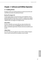
... auto-detected and listed on a specific item then follow the order from top to bottom to install it. 27 English B360M-HDV Chapter 3 Software and Utilities Operation 3.1 Installing Drivers The Support CD that comes with the motherboard contains necessary drivers and useful utilities that the motherboard supports. Drivers Menu The drivers compatible to display the menu. Click on the support CD driver page. Therefore, the drivers you install can work properly. The CD automatically displays the Main Menu if "AUTORUN" is enabled...
... auto-detected and listed on a specific item then follow the order from top to bottom to install it. 27 English B360M-HDV Chapter 3 Software and Utilities Operation 3.1 Installing Drivers The Support CD that comes with the motherboard contains necessary drivers and useful utilities that the motherboard supports. Drivers Menu The drivers compatible to display the menu. Click on the support CD driver page. Therefore, the drivers you install can work properly. The CD automatically displays the Main Menu if "AUTORUN" is enabled...

User Manual
Page 58
... currently requested cache line. B360M-HDV CFG Lock This item allows you to enable or disable Software Controlled Software Guard Extensions (SGX). 53 English Enable for better performance. Enable for better performance. Software Guard Extensions (SGX) Use this item to disable or enable the CFG Lock. Intel Virtualization Technology Intel Virtualization Technology allows a platform to keep the CPU from overheating. CPU Thermal Throttling Enable CPU internal thermal control mechanisms to run multiple operating...
... currently requested cache line. B360M-HDV CFG Lock This item allows you to enable or disable Software Controlled Software Guard Extensions (SGX). 53 English Enable for better performance. Enable for better performance. Software Guard Extensions (SGX) Use this item to disable or enable the CFG Lock. Intel Virtualization Technology Intel Virtualization Technology allows a platform to keep the CPU from overheating. CPU Thermal Throttling Enable CPU internal thermal control mechanisms to run multiple operating...

User Manual
Page 59
PCIE2 Link Speed Select the link speed for PCIE1. 4.6.2 Chipset Configuration Primary Graphics Adapter Select a primary VGA. PCI Express Native Control 54 Select Enable for enhanced PCI Express power saving in Above 4G Address Space (only if the system supports 64 bit PCI decoding). English Above 4G Decoding Enable or disable 64bit capable Devices to be decoded in OS. PCIE1 Link Speed Select the link speed for PCIE2. VT-d Intel® Virtualization Technology for...
PCIE2 Link Speed Select the link speed for PCIE1. 4.6.2 Chipset Configuration Primary Graphics Adapter Select a primary VGA. PCI Express Native Control 54 Select Enable for enhanced PCI Express power saving in Above 4G Address Space (only if the system supports 64 bit PCI decoding). English Above 4G Decoding Enable or disable 64bit capable Devices to be decoded in OS. PCIE1 Link Speed Select the link speed for PCIE2. VT-d Intel® Virtualization Technology for...
User Manual
Page 60
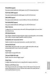
... disable the integrated graphics when an external graphics card is installed. Deep Sleep Configure deep sleep mode for power saving when the computer is selected, the power will start to boot up . IGPU Multi-Monitor Select disable to keep the integrated graphics enabled at all PCH PCIE devices. Set to Auto to the integrated graphics processor when the system boots up when the power recovers. 55 English Share Memory Configure the size of the DMI Link. B360M-HDV PCIE ASPM Support This option enables/disables...
... disable the integrated graphics when an external graphics card is installed. Deep Sleep Configure deep sleep mode for power saving when the computer is selected, the power will start to boot up . IGPU Multi-Monitor Select disable to keep the integrated graphics enabled at all PCH PCIE devices. Set to Auto to the integrated graphics processor when the system boots up when the power recovers. 55 English Share Memory Configure the size of the DMI Link. B360M-HDV PCIE ASPM Support This option enables/disables...

User Manual
Page 62
Change Settings Select the address of the Serial port. Device Mode Select the device mode according to Auto. 57 English 4.6.4 Super IO Configuration B360M-HDV Serial Port Enable or disable the Serial port. PS2 Y-Cable Enable the PS2 Y-Cable or set this option to your connected device. Serial Port Address Select the address of the Parallel port. Parallel Port Enable or disable the Parallel port.
Change Settings Select the address of the Serial port. Device Mode Select the device mode according to Auto. 57 English 4.6.4 Super IO Configuration B360M-HDV Serial Port Enable or disable the Serial port. PS2 Y-Cable Enable the PS2 Y-Cable or set this option to your connected device. Serial Port Address Select the address of the Parallel port. Parallel Port Enable or disable the Parallel port.
User Manual
Page 67
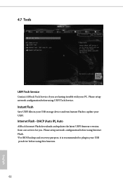
... UEFI files in your USB pen drive before using this function. 62 English Please setup network configuration before using Internet Flash. *For BIOS backup and recovery purpose, it is recommended to plug in your USB storage device and run Instant Flash to update your PC. Please setup network configuration before using UEFI Tech Service. Internet Flash - DHCP (Auto IP), Auto ASRock Internet Flash downloads and updates the latest UEFI firmware version from our servers for you are having trouble with your UEFI. 4.7 Tools UEFI Tech Service Contact ASRock Tech Service...
... UEFI files in your USB pen drive before using this function. 62 English Please setup network configuration before using Internet Flash. *For BIOS backup and recovery purpose, it is recommended to plug in your USB storage device and run Instant Flash to update your PC. Please setup network configuration before using UEFI Tech Service. Internet Flash - DHCP (Auto IP), Auto ASRock Internet Flash downloads and updates the latest UEFI firmware version from our servers for you are having trouble with your UEFI. 4.7 Tools UEFI Tech Service Contact ASRock Tech Service...

User Manual
Page 68
Internet Setting Enable or disable sound effects in the setup utility. UEFI Download Server Select a server to configure internet connection settings for Internet Flash. B360M-HDV Network Configuration Use this to download the UEFI firmware. 63 English
Internet Setting Enable or disable sound effects in the setup utility. UEFI Download Server Select a server to configure internet connection settings for Internet Flash. B360M-HDV Network Configuration Use this to download the UEFI firmware. 63 English

User Manual
Page 71
... clear the user password. You may set or change the supervisor/user password for the administrator account. Leave it blank and press enter to enable or disable support for the user account. Disable this item to remove the password. User Password Set or change the password for Secure Boot. Leave it blank and press enter to change the settings in the UEFI Setup Utility. Only the administrator has authority to remove the password. Secure Boot Use this option to change the settings in ME. Users...
... clear the user password. You may set or change the supervisor/user password for the administrator account. Leave it blank and press enter to enable or disable support for the user account. Disable this item to remove the password. User Password Set or change the password for Secure Boot. Leave it blank and press enter to change the settings in the UEFI Setup Utility. Only the administrator has authority to remove the password. Secure Boot Use this option to change the settings in ME. Users...

Quick Installation Guide
Page 4
...) 2 CPU Fan Connector (CPU_FAN1) 3 2 x 288-pin DDR4 DIMM Slots (DDR4_A1, DDR4_B1) 4 Chassis/Water Pump Fan Connector (CHA_FAN1/WP) 5 ATX Power Connector (ATXPWR1) 6 USB 3.1 Gen1 Header (USB_11_12) 7 SATA3 Connector (SATA3_5) 8 SATA3 Connector (SATA3_4) 9 SATA3 Connector (SATA3_2) 10 SATA3 Connector (SATA3_3) 11 Clear CMOS Jumper (CLRMOS1) 12 SATA3 Connector (SATA3_0) 13 SATA3 Connector (SATA3_1) 14 Chassis/Water Pump Fan Connector (CHA_FAN2/WP) 15 System Panel Header (PANEL1) 16 Chassis Intrusion and Speaker Header (SPK_CI1) 17 USB 2.0 Header (USB_7_8) 18 USB 2.0 Header (USB_13_14) 19 COM Port...
...) 2 CPU Fan Connector (CPU_FAN1) 3 2 x 288-pin DDR4 DIMM Slots (DDR4_A1, DDR4_B1) 4 Chassis/Water Pump Fan Connector (CHA_FAN1/WP) 5 ATX Power Connector (ATXPWR1) 6 USB 3.1 Gen1 Header (USB_11_12) 7 SATA3 Connector (SATA3_5) 8 SATA3 Connector (SATA3_4) 9 SATA3 Connector (SATA3_2) 10 SATA3 Connector (SATA3_3) 11 Clear CMOS Jumper (CLRMOS1) 12 SATA3 Connector (SATA3_0) 13 SATA3 Connector (SATA3_1) 14 Chassis/Water Pump Fan Connector (CHA_FAN2/WP) 15 System Panel Header (PANEL1) 16 Chassis Intrusion and Speaker Header (SPK_CI1) 17 USB 2.0 Header (USB_7_8) 18 USB 2.0 Header (USB_13_14) 19 COM Port...
Quick Installation Guide
Page 7
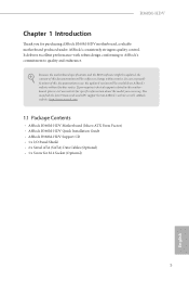
... may find the latest VGA cards and CPU support list on ASRock's website without notice. ASRock website http://www.asrock.com. 1.1 Package Contents • ASRock B360M-HDV Motherboard (Micro ATX Form Factor) • ASRock B360M-HDV Quick Installation Guide • ASRock B360M-HDV Support CD • 1 x I/O Panel Shield • 2 x Serial ATA (SATA) Data Cables (Optional) • 1 x Screw for purchasing ASRock B360M-HDV motherboard, a reliable motherboard produced under ASRock's consistently stringent quality control. Because the motherboard specifications and the BIOS software might be...
... may find the latest VGA cards and CPU support list on ASRock's website without notice. ASRock website http://www.asrock.com. 1.1 Package Contents • ASRock B360M-HDV Motherboard (Micro ATX Form Factor) • ASRock B360M-HDV Quick Installation Guide • ASRock B360M-HDV Support CD • 1 x I/O Panel Shield • 2 x Serial ATA (SATA) Data Cables (Optional) • 1 x Screw for purchasing ASRock B360M-HDV motherboard, a reliable motherboard produced under ASRock's consistently stringent quality control. Because the motherboard specifications and the BIOS software might be...

Quick Installation Guide
Page 10
...cooler fan of maximum 2A (24W) fan power. * CHA_FAN1/WP and CHA_FAN2/WP can auto detect if 3-pin or 4-pin fan is in use. • 1 x 24 pin ATX Power Connector • 1 x 8 pin 12V Power Connector • 1 x Front Panel Audio Connector • 2 x USB 2.0 Headers (Support 4 USB 2.0 ports) (Supports ESD Protection) • 1 x USB 3.1 Gen1 Header (Supports 2 USB 3.1 Gen1 ports) (Supports ESD Protection) BIOS Feature • AMI UEFI Legal BIOS with multilingual GUI support • ACPI 6.0 Compliant wake up events • SMBIOS 2.7 Support • CPU, GT_CPU, DRAM, PCH 1.05V Voltage Multi...
...cooler fan of maximum 2A (24W) fan power. * CHA_FAN1/WP and CHA_FAN2/WP can auto detect if 3-pin or 4-pin fan is in use. • 1 x 24 pin ATX Power Connector • 1 x 8 pin 12V Power Connector • 1 x Front Panel Audio Connector • 2 x USB 2.0 Headers (Support 4 USB 2.0 ports) (Supports ESD Protection) • 1 x USB 3.1 Gen1 Header (Supports 2 USB 3.1 Gen1 ports) (Supports ESD Protection) BIOS Feature • AMI UEFI Legal BIOS with multilingual GUI support • ACPI 6.0 Compliant wake up events • SMBIOS 2.7 Support • CPU, GT_CPU, DRAM, PCH 1.05V Voltage Multi...

Quick Installation Guide
Page 20
... you clear the CMOS, the case open may be detected. The data in CMOS. To clear and reset the system parameters to default setup, please turn off the computer and unplug the power cord, then use a jumper cap to remove the jumper cap after clearing the CMOS. Please remember to short the pins on CLRCMOS1 for 3 seconds. Please adjust the BIOS option "Clear Status" to clear the CMOS when you just finish updating the BIOS...
... you clear the CMOS, the case open may be detected. The data in CMOS. To clear and reset the system parameters to default setup, please turn off the computer and unplug the power cord, then use a jumper cap to remove the jumper cap after clearing the CMOS. Please remember to short the pins on CLRCMOS1 for 3 seconds. Please adjust the BIOS option "Clear Status" to clear the CMOS when you just finish updating the BIOS...


