User Manual
Page 2
... particular purpose. This device complies with Part 15 of this documentation. CALIFORNIA, USA ONLY The Lithium battery adopted on this motherboard contains Perchlorate, a toxic substance controlled in this device must accept any kind, either expressed or implied, including but not ... to the following two conditions: (1) this device may apply, see www.dtsc.ca.gov/hazardouswaste/ perchlorate" ASRock Website: http://www.asrock.com ASRock assumes no event shall ASRock, its directors, officers, employees, or agents be constructed as a commitment by the California Legislature. Operation is...
... particular purpose. This device complies with Part 15 of this documentation. CALIFORNIA, USA ONLY The Lithium battery adopted on this motherboard contains Perchlorate, a toxic substance controlled in this device must accept any kind, either expressed or implied, including but not ... to the following two conditions: (1) this device may apply, see www.dtsc.ca.gov/hazardouswaste/ perchlorate" ASRock Website: http://www.asrock.com ASRock assumes no event shall ASRock, its directors, officers, employees, or agents be constructed as a commitment by the California Legislature. Operation is...
User Manual
Page 4
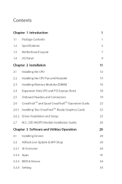
Contents Chapter 1 Introduction 1 1.1 Package Contents 1 1.2 Specifications 2 1.3 Motherboard Layout 7 1.4 I/O Panel 9 Chapter 2 Installation 11 2.1 Installing the CPU 12 2.2 Installing the CPU Fan and Heatsink 15 2.3 Installing Memory Modules (DIMM) 16 2.4 Expansion Slots...Graphics Cards 23 2.6.2 Driver Installation and Setup 25 2.7 M.2_SSD (NGFF) Module Installation Guide 26 Chapter 3 Software and Utilities Operation 29 3.1 Installing Drivers 29 3.2 ASRock Live Update & APP Shop 30 3.2.1 UI Overview 30 3.2.2 Apps 31 3.2.3 BIOS & Drivers 34 3.2.4 Setting 35
Contents Chapter 1 Introduction 1 1.1 Package Contents 1 1.2 Specifications 2 1.3 Motherboard Layout 7 1.4 I/O Panel 9 Chapter 2 Installation 11 2.1 Installing the CPU 12 2.2 Installing the CPU Fan and Heatsink 15 2.3 Installing Memory Modules (DIMM) 16 2.4 Expansion Slots...Graphics Cards 23 2.6.2 Driver Installation and Setup 25 2.7 M.2_SSD (NGFF) Module Installation Guide 26 Chapter 3 Software and Utilities Operation 29 3.1 Installing Drivers 29 3.2 ASRock Live Update & APP Shop 30 3.2.1 UI Overview 30 3.2.2 Apps 31 3.2.3 BIOS & Drivers 34 3.2.4 Setting 35
User Manual
Page 6
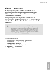
... 3 contains the operation guide of the motherboard and step-by-step installation guides. ASRock website http://www.asrock.com. 1.1 Package Contents • ASRock B250M Pro4 Motherboard (Micro ATX Form Factor) • ASRock B250M Pro4 Quick Installation Guide • ASRock B250M Pro4 Support CD • 2 x Serial ATA (SATA) Data Cables (Optional) • 2 x Screws for purchasing ASRock B250M Pro4 motherboard, a reliable motherboard produced under ASRock's consistently stringent quality control. You may...
... 3 contains the operation guide of the motherboard and step-by-step installation guides. ASRock website http://www.asrock.com. 1.1 Package Contents • ASRock B250M Pro4 Motherboard (Micro ATX Form Factor) • ASRock B250M Pro4 Quick Installation Guide • ASRock B250M Pro4 Support CD • 2 x Serial ATA (SATA) Data Cables (Optional) • 2 x Screws for purchasing ASRock B250M Pro4 motherboard, a reliable motherboard produced under ASRock's consistently stringent quality control. You may...
User Manual
Page 12
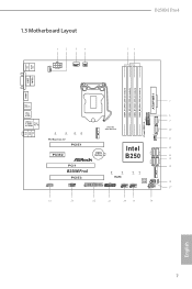
1.3 Motherboard Layout CHA_FAN1 ATX12V1 CPU_FAN1 CPU_FAN2 B250M Pro4 PS2 Mouse PS2 Keyboard VGA1 DVI1 DDR4_A1 (64 bit, 288-pin module) DDR4_A2 (64 bit, 288-pin module) DDR4_B1 (64 bit, 288-pin module) DDR4_B2 (... Top: RJ-45 CT4 CT3 PCI Express 3.0 CT2 Ct1 PCIE1 PCIE2 Ultra M.2 PCIe Gen3 x4 M2_1 Intel CMOS Battery B250 SATA3_2 CHA_FAN2 SATA3_4 HD_AUDIO1 1 PCI1 B250M Pro4 PCIE3 COM1 1 1 LPT1 CT4 CT3 CT2 RoHS TPMS1 1 USB3_4 USB5_6 1 1 Ct1 CLRMOS1 BIOS SPK_CI1 1 ROM 1 PLED PWRBTN 1 HDLED RESET PANEL1 M2_2 SATA3_3 SATA3_5 English...
1.3 Motherboard Layout CHA_FAN1 ATX12V1 CPU_FAN1 CPU_FAN2 B250M Pro4 PS2 Mouse PS2 Keyboard VGA1 DVI1 DDR4_A1 (64 bit, 288-pin module) DDR4_A2 (64 bit, 288-pin module) DDR4_B1 (64 bit, 288-pin module) DDR4_B2 (... Top: RJ-45 CT4 CT3 PCI Express 3.0 CT2 Ct1 PCIE1 PCIE2 Ultra M.2 PCIe Gen3 x4 M2_1 Intel CMOS Battery B250 SATA3_2 CHA_FAN2 SATA3_4 HD_AUDIO1 1 PCI1 B250M Pro4 PCIE3 COM1 1 1 LPT1 CT4 CT3 CT2 RoHS TPMS1 1 USB3_4 USB5_6 1 1 Ct1 CLRMOS1 BIOS SPK_CI1 1 ROM 1 PLED PWRBTN 1 HDLED RESET PANEL1 M2_2 SATA3_3 SATA3_5 English...
User Manual
Page 16
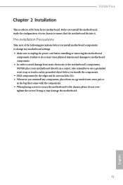
... do not touch the ICs. • Whenever you install motherboard components or change any components, place them on a carpet. B250M Pro4 Chapter 2 Installation This is a Micro ATX form factor motherboard. Pre-installation Precautions Take note of your chassis to the motherboard's components, NEVER place your motherboard directly on a grounded anti-static pad or in the bag...
... do not touch the ICs. • Whenever you install motherboard components or change any components, place them on a carpet. B250M Pro4 Chapter 2 Installation This is a Micro ATX form factor motherboard. Pre-installation Precautions Take note of your chassis to the motherboard's components, NEVER place your motherboard directly on a grounded anti-static pad or in the bag...
User Manual
Page 19
Please save and replace the cover if the processor is removed. The cover must be placed if you wish to return the motherboard for after service. 14 English
Please save and replace the cover if the processor is removed. The cover must be placed if you wish to return the motherboard for after service. 14 English
User Manual
Page 21
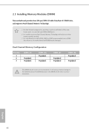
... DIMM pairs. 2. For dual channel configuration, you force the DIMM into a DDR4 slot; It is not allowed to the motherboard and the DIMM if you always need to activate Dual Channel Memory Technology with only one correct orientation. 2.3 Installing Memory Modules (DIMM) ...This motherboard provides four 288-pin DDR4 (Double Data Rate 4) DIMM slots, and supports Dual Channel Memory Technology. 1. Dual Channel Memory Configuration Priority...
... DIMM pairs. 2. For dual channel configuration, you force the DIMM into a DDR4 slot; It is not allowed to the motherboard and the DIMM if you always need to activate Dual Channel Memory Technology with only one correct orientation. 2.3 Installing Memory Modules (DIMM) ...This motherboard provides four 288-pin DDR4 (Double Data Rate 4) DIMM slots, and supports Dual Channel Memory Technology. 1. Dual Channel Memory Configuration Priority...
User Manual
Page 23
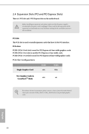
PCI slot: The PCI1 slot is used to the motherboard's chassis fan connector (CHA_FAN1 or CHA_FAN2) when using multiple graphics cards. PCIe Slot Configurations Single Graphics Card PCIE1 x16 PCIE3 N/A Two Graphics Cards in CrossFireXTM ... make necessary hardware settings for the card before you start the installation. PCIE3 (PCIe 3.0 x16 slot) is 1 PCI slot and 3 PCI Express slots on the motherboard.
PCI slot: The PCI1 slot is used to the motherboard's chassis fan connector (CHA_FAN1 or CHA_FAN2) when using multiple graphics cards. PCIe Slot Configurations Single Graphics Card PCIE1 x16 PCIE3 N/A Two Graphics Cards in CrossFireXTM ... make necessary hardware settings for the card before you start the installation. PCIE3 (PCIe 3.0 x16 slot) is 1 PCI slot and 3 PCI Express slots on the motherboard.

User Manual
Page 24
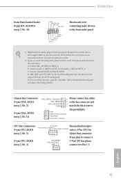
... by chassis. The LED is on when the hard drive is operating. When connecting your system using the power switch. English 19 B250M Pro4 2.5 Onboard Headers and Connectors Onboard headers and connectors are matched correctly. Do NOT place jumper caps over the headers and connectors will ... sure the wire assignments and the pin assignments are NOT jumpers. PWRBTN (Power Switch): Connect to the power status indicator on the chassis to the motherboard. System Panel Header (9-pin PANEL1) (see p.7, No. 18) PLED+ PLEDPWRBTN# GND 1 GND RESET# GND HDLEDHDLED+ Connect the power switch,...
... by chassis. The LED is on when the hard drive is operating. When connecting your system using the power switch. English 19 B250M Pro4 2.5 Onboard Headers and Connectors Onboard headers and connectors are matched correctly. Do NOT place jumper caps over the headers and connectors will ... sure the wire assignments and the pin assignments are NOT jumpers. PWRBTN (Power Switch): Connect to the power status indicator on the chassis to the motherboard. System Panel Header (9-pin PANEL1) (see p.7, No. 18) PLED+ PLEDPWRBTN# GND 1 GND RESET# GND HDLEDHDLED+ Connect the power switch,...
User Manual
Page 25
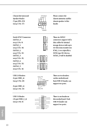
...SATA data cables for internal storage devices with up to this header. If M2_1 is one header on this motherboard. Each USB 2.0 header can support two ports. SATA3_5 SATA3_3 SATA3_4 SATA3_2 USB_PWR PP+ GND DUMMY 1 GND P+ PUSB_PWR ...There are two headers on this motherboard. USB 3.0 Header (19-pin USB3_5_6) (see p.7, No. 8) Vbus IntA_PA_SSRXIntA_PA_SSRX+ GND IntA_PA_SSTXIntA_PA_SSTX+ GND IntA_PA_DIntA_PA_D+ Vbus IntA_PB_SSRXIntA_PB_SSRX+ GND IntA_PB_SSTXIntA_PB_SSTX+...
...SATA data cables for internal storage devices with up to this header. If M2_1 is one header on this motherboard. Each USB 2.0 header can support two ports. SATA3_5 SATA3_3 SATA3_4 SATA3_2 USB_PWR PP+ GND DUMMY 1 GND P+ PUSB_PWR ...There are two headers on this motherboard. USB 3.0 Header (19-pin USB3_5_6) (see p.7, No. 8) Vbus IntA_PA_SSRXIntA_PA_SSRX+ GND IntA_PA_SSTXIntA_PA_SSTX+ GND IntA_PA_DIntA_PA_D+ Vbus IntA_PB_SSRXIntA_PB_SSRX+ GND IntA_PB_SSTXIntA_PB_SSTX+...
User Manual
Page 26
... the black wire to the front panel audio header by the steps below: A. MIC_RET and OUT_RET are for the AC'97 audio panel. E. D. English 21 B250M Pro4 Front Panel Audio Header (9-pin HD_AUDIO1) (see p.7, No. 24) GND PRESENCE# MIC_RET OUT_RET 1 OUT2_L J_SENSE OUT2_R MIC2_R MIC2_L This header is for connecting audio devices... must support HDA to Ground (GND). B. C. Connect Ground (GND) to function correctly. Chassis Fan Connectors (4-pin CHA_FAN1) (see p.7, No. 2) (4-pin CHA_FAN2) (see p.7, No. 4) FAN_SPEED This motherboard pro-
... the black wire to the front panel audio header by the steps below: A. MIC_RET and OUT_RET are for the AC'97 audio panel. E. D. English 21 B250M Pro4 Front Panel Audio Header (9-pin HD_AUDIO1) (see p.7, No. 24) GND PRESENCE# MIC_RET OUT_RET 1 OUT2_L J_SENSE OUT2_R MIC2_R MIC2_L This header is for connecting audio devices... must support HDA to Ground (GND). B. C. Connect Ground (GND) to function correctly. Chassis Fan Connectors (4-pin CHA_FAN1) (see p.7, No. 2) (4-pin CHA_FAN2) (see p.7, No. 4) FAN_SPEED This motherboard pro-
User Manual
Page 27
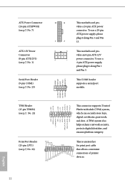
... SMB_CLK_MAIN This connector supports Trusted Platform Module (TPM) system, 1 which can securely store keys, digital certificates, passwords, and data. This motherboard provides an 8-pin ATX 12V power connector. This COM1 header supports a serial port module. A TPM system also helps enhance network security,...3V LAD3 PCIRST # FRAM E PCICLK GN D English TPM Header (17-pin TPMS1) (see p.7, No. 23) 12 24 1 13 8 5 4 1 This motherboard provides a 24-pin ATX power connector. Print Port Header (25-pin LPT1) (see p.7, No. 22) AFD# ERROR# PINIT# SLIN# GND 1 SPD7 SPD6 ACK...
... SMB_CLK_MAIN This connector supports Trusted Platform Module (TPM) system, 1 which can securely store keys, digital certificates, passwords, and data. This motherboard provides an 8-pin ATX 12V power connector. This COM1 header supports a serial port module. A TPM system also helps enhance network security,...3V LAD3 PCIRST # FRAM E PCICLK GN D English TPM Header (17-pin TPMS1) (see p.7, No. 23) 12 24 1 13 8 5 4 1 This motherboard provides a 24-pin ATX power connector. Print Port Header (25-pin LPT1) (see p.7, No. 22) AFD# ERROR# PINIT# SLIN# GND 1 SPD7 SPD6 ACK...
User Manual
Page 28
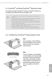
...PCI Express x16 graphics cards. 1. Download the drivers from the AMD's website: www.amd.com 3. B250M Pro4 2.6 CrossFireXTM and Quad CrossFireXTM Operation Guide This motherboard supports CrossFireXTM and Quad CrossFireXTM that allows you to install up to enable CrossFireXTM. Make sure that your... graphics card driver supports AMD CrossFireXTM technology. If you pair a 12-pipe CrossFireXTM Edition card with this motherboard. Please refer to use identical CrossFireXTM-ready graphics cards that the cards are AMD certified. 2. Please refer to your system ...
...PCI Express x16 graphics cards. 1. Download the drivers from the AMD's website: www.amd.com 3. B250M Pro4 2.6 CrossFireXTM and Quad CrossFireXTM Operation Guide This motherboard supports CrossFireXTM and Quad CrossFireXTM that allows you to install up to enable CrossFireXTM. Make sure that your... graphics card driver supports AMD CrossFireXTM technology. If you pair a 12-pipe CrossFireXTM Edition card with this motherboard. Please refer to use identical CrossFireXTM-ready graphics cards that the cards are AMD certified. 2. Please refer to your system ...
User Manual
Page 32
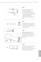
... location on the module type and length. Please do not overtighten the screw as this might damage the module. 5 4 3 2 1 E D C B A E D C B A E D C B A C B A E D NUT2 NUT1 B250M Pro4 Step 3 Move the standoff based on the motherboard. English 27 Step 4 Peel off the yellow protective film on the nut to use the default nut. Step 5 Align and gently insert...
... location on the module type and length. Please do not overtighten the screw as this might damage the module. 5 4 3 2 1 E D C B A E D C B A E D C B A C B A E D NUT2 NUT1 B250M Pro4 Step 3 Move the standoff based on the motherboard. English 27 Step 4 Peel off the yellow protective film on the nut to use the default nut. Step 5 Align and gently insert...
User Manual
Page 34
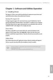
.... Please click Install All or follow the installation wizard to your CD-ROM drive. B250M Pro4 Chapter 3 Software and Utilities Operation 3.1 Installing Drivers The Support CD that comes with the motherboard contains necessary drivers and useful utilities that the motherboard supports. Running The Support CD To begin using the support CD, insert the CD...
.... Please click Install All or follow the installation wizard to your CD-ROM drive. B250M Pro4 Chapter 3 Software and Utilities Operation 3.1 Installing Drivers The Support CD that comes with the motherboard contains necessary drivers and useful utilities that the motherboard supports. Running The Support CD To begin using the support CD, insert the CD...
User Manual
Page 35
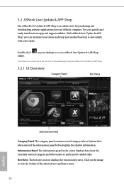
...motherboard up to visit the website of the selected news and know more. 30 English on the image to date simply with a few clicks. Information Panel: The information panel in the center displays data about the currently selected category and allows users to download apps from the ASRock...news section displays the various latest news. Click on your ASRock computer. Double-click utility. With ASRock Live Update & APP Shop, you can quickly and easily install various apps and support utilities. 3.2 ASRock Live Update & APP Shop The ASRock Live Update & APP Shop is an online store for ...
...motherboard up to visit the website of the selected news and know more. 30 English on the image to date simply with a few clicks. Information Panel: The information panel in the center displays data about the currently selected category and allows users to download apps from the ASRock...news section displays the various latest news. Click on your ASRock computer. Double-click utility. With ASRock Live Update & APP Shop, you can quickly and easily install various apps and support utilities. 3.2 ASRock Live Update & APP Shop The ASRock Live Update & APP Shop is an online store for ...
User Manual
Page 41
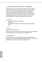
... and only kept the eXtensible Host Controller Interface (XHCI - 3.3 Enabling USB Ports for Windows® 7 Installation Intel® new processors have removed their motherboard won't work. In order for the Enhanced Host Controller Interface (EHCI - You've got nothing: If you do not have an ODD and PS/2 ports...: If there is not included in the ASRock Support CD or downloaded from website) Scenarios You have an optical disc drive, please find it difficult to install Windows 7 operating system because the ...
... and only kept the eXtensible Host Controller Interface (XHCI - 3.3 Enabling USB Ports for Windows® 7 Installation Intel® new processors have removed their motherboard won't work. In order for the Enhanced Host Controller Interface (EHCI - You've got nothing: If you do not have an ODD and PS/2 ports...: If there is not included in the ASRock Support CD or downloaded from website) Scenarios You have an optical disc drive, please find it difficult to install Windows 7 operating system because the ...
User Manual
Page 51
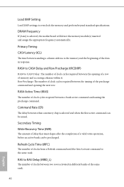
... of clocks from a Refresh command until the first Activate command to RAS Delay (tRRD_L) The number of clocks between when a memory chip is selected, the motherboard will detect the memory module(s) inserted and assign the appropriate frequency automatically. Load XMP Setting Load XMP settings to the memory and the beginning of...
... of clocks from a Refresh command until the first Activate command to RAS Delay (tRRD_L) The number of clocks between when a memory chip is selected, the motherboard will detect the memory module(s) inserted and assign the appropriate frequency automatically. Load XMP Setting Load XMP settings to the memory and the beginning of...
User Manual
Page 70
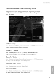
... temperature. CPU Fan 1 & 2 Setting Select a fan mode for CPU Fan 1 & 2, or choose Customize to set 5 CPU temperatures and assign a respective fan speed for each temperature. B250M Pro4 4.8 Hardware Health Event Monitoring Screen This section allows you to set 5 CPU temperatures and assign a respective fan speed for each temperature. Chassis Fan 1 Setting Select... a fan mode for CPU Fan, or choose Customize to monitor the status of the hardware on your system, including the parameters of the CPU temperature, motherboard temperature, fan speed and voltage.
... temperature. CPU Fan 1 & 2 Setting Select a fan mode for CPU Fan 1 & 2, or choose Customize to set 5 CPU temperatures and assign a respective fan speed for each temperature. B250M Pro4 4.8 Hardware Health Event Monitoring Screen This section allows you to set 5 CPU temperatures and assign a respective fan speed for each temperature. Chassis Fan 1 Setting Select... a fan mode for CPU Fan, or choose Customize to monitor the status of the hardware on your system, including the parameters of the CPU temperature, motherboard temperature, fan speed and voltage.
User Manual
Page 71
Chassis Fan 2 Temp Source Select a fan temperature source for Chassis Fan 2. Case Open Feature Enable or disable Case Open Feature to detect whether the chassis cover has been removed. 66 English Over Temperature Protection When Over Temperature Protection is enabled, the system automatically shuts down when the motherboard is overheated.
Chassis Fan 2 Temp Source Select a fan temperature source for Chassis Fan 2. Case Open Feature Enable or disable Case Open Feature to detect whether the chassis cover has been removed. 66 English Over Temperature Protection When Over Temperature Protection is enabled, the system automatically shuts down when the motherboard is overheated.


