User Manual
Page 4
... the CPU 12 2.2 Installing the CPU Fan and Heatsink 15 2.3 Installing Memory Modules (DIMM) 16 2.4 Expansion Slots (PCI and PCI Express Slots) 18 2.5 Onboard Headers and Connectors 19 2.6 CrossFireXTM and Quad CrossFireXTM Operation Guide 23 2.6.1 Installing Two CrossFireXTM-Ready Graphics Cards 23 2.6.2 Driver Installation and Setup 25 2.7 M.2_SSD (NGFF) Module Installation Guide 26 Chapter 3 Software and Utilities Operation 29 3.1 Installing Drivers 29 3.2 ASRock Live Update & APP Shop 30 3.2.1 UI Overview 30 3.2.2 Apps 31 3.2.3 BIOS & Drivers 34 3.2.4 Setting...
... the CPU 12 2.2 Installing the CPU Fan and Heatsink 15 2.3 Installing Memory Modules (DIMM) 16 2.4 Expansion Slots (PCI and PCI Express Slots) 18 2.5 Onboard Headers and Connectors 19 2.6 CrossFireXTM and Quad CrossFireXTM Operation Guide 23 2.6.1 Installing Two CrossFireXTM-Ready Graphics Cards 23 2.6.2 Driver Installation and Setup 25 2.7 M.2_SSD (NGFF) Module Installation Guide 26 Chapter 3 Software and Utilities Operation 29 3.1 Installing Drivers 29 3.2 ASRock Live Update & APP Shop 30 3.2.1 UI Overview 30 3.2.2 Apps 31 3.2.3 BIOS & Drivers 34 3.2.4 Setting...
User Manual
Page 6
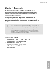
...Package Contents • ASRock B250M Pro4 Motherboard (Micro ATX Form Factor) • ASRock B250M Pro4 Quick Installation Guide • ASRock B250M Pro4 Support CD • 2 x Serial ATA (SATA) Data Cables (Optional) • 2 x Screws for purchasing ASRock B250M Pro4 motherboard, a reliable motherboard produced under ASRock's consistently stringent quality control. B250M Pro4 Chapter 1 Introduction Thank you are using. In this documentation will be subject to quality and endurance. Because the motherboard specifications and the BIOS software might be updated, the content of...
...Package Contents • ASRock B250M Pro4 Motherboard (Micro ATX Form Factor) • ASRock B250M Pro4 Quick Installation Guide • ASRock B250M Pro4 Support CD • 2 x Serial ATA (SATA) Data Cables (Optional) • 2 x Screws for purchasing ASRock B250M Pro4 motherboard, a reliable motherboard produced under ASRock's consistently stringent quality control. B250M Pro4 Chapter 1 Introduction Thank you are using. In this documentation will be subject to quality and endurance. Because the motherboard specifications and the BIOS software might be updated, the content of...
User Manual
Page 8
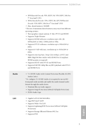
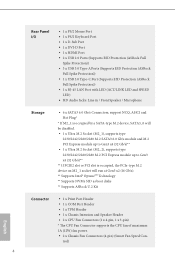
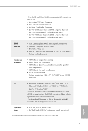
... HDMI Ports • 7.1 CH HD Audio with max. B250M Pro4 Audio LAN • HWAEncode/Decode: VP8, HEVC 8b, VP9, HEVC 10b (For 7th Gen Intel® CPU) • HWA Encode/Decode: VP8 , HEVC 8b; resolution up to use an HD front panel audio module and enable the multi-channel audio feature through the audio driver. • Premium Blu-ray Audio support • Supports Surge Protection (ASRock Full Spike Protection) • ELNA Audio...
... HDMI Ports • 7.1 CH HD Audio with max. B250M Pro4 Audio LAN • HWAEncode/Decode: VP8, HEVC 8b, VP9, HEVC 10b (For 7th Gen Intel® CPU) • HWA Encode/Decode: VP8 , HEVC 8b; resolution up to use an HD front panel audio module and enable the multi-channel audio feature through the audio driver. • Premium Blu-ray Audio support • Supports Surge Protection (ASRock Full Spike Protection) • ELNA Audio...
User Manual
Page 9
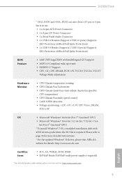
...Express module up to Gen3 x4 (32 Gb/s)** ** If PCIE2 slot or PCI slot is occupied, the PCIe-type M.2 device on M2_1 socket will run at Gen3 x2 (16 Gb/s). ** Supports Intel® OptaneTM Technology ** Supports NVMe SSD as boot disks ** Supports ASRock U.2 Kit English Connector • 1 x Print Port Header • 1 x COM Port Header • 1 x TPM Header • 1 x Chassis Intrusion and Speaker Header • 2 x CPU Fan Connectors (1 x 4-pin, 1 x 3-pin) * The CPU Fan Connector supports the CPU fan of maximum 1A (12W) fan power. • 2 x Chassis Fan Connectors (4-pin) (Smart Fan Speed...
...Express module up to Gen3 x4 (32 Gb/s)** ** If PCIE2 slot or PCI slot is occupied, the PCIe-type M.2 device on M2_1 socket will run at Gen3 x2 (16 Gb/s). ** Supports Intel® OptaneTM Technology ** Supports NVMe SSD as boot disks ** Supports ASRock U.2 Kit English Connector • 1 x Print Port Header • 1 x COM Port Header • 1 x TPM Header • 1 x Chassis Intrusion and Speaker Header • 2 x CPU Fan Connectors (1 x 4-pin, 1 x 3-pin) * The CPU Fan Connector supports the CPU fan of maximum 1A (12W) fan power. • 2 x Chassis Fan Connectors (4-pin) (Smart Fan Speed...
User Manual
Page 10
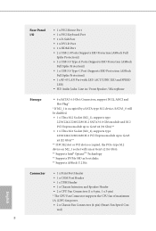
...can auto detect if 3-pin or 4-pin fan is in use. • 1 x 24 pin ATX Power Connector • 1 x 8 pin 12V Power Connector • 1 x Front Panel Audio Connector • 2 x USB 2.0 Headers (Support 4 USB 2.0 ports) (Supports ESD Protection (ASRock Full Spike Protection)) • 1 x USB 3.0 Header (Supports 2 USB 3.0 ports) (Supports ESD Protection (ASRock Full Spike Protection)) BIOS Feature • AMI UEFI Legal BIOS with multilingual GUI support • ACPI 6.0 Compliant wake up events • SMBIOS 2.7 Support • CPU, GT_CPU, DRAM, PCH 1.0V, VCCIO, VCCSA, VCCST Voltage Multi...
...can auto detect if 3-pin or 4-pin fan is in use. • 1 x 24 pin ATX Power Connector • 1 x 8 pin 12V Power Connector • 1 x Front Panel Audio Connector • 2 x USB 2.0 Headers (Support 4 USB 2.0 ports) (Supports ESD Protection (ASRock Full Spike Protection)) • 1 x USB 3.0 Header (Supports 2 USB 3.0 ports) (Supports ESD Protection (ASRock Full Spike Protection)) BIOS Feature • AMI UEFI Legal BIOS with multilingual GUI support • ACPI 6.0 Compliant wake up events • SMBIOS 2.7 Support • CPU, GT_CPU, DRAM, PCH 1.0V, VCCIO, VCCSA, VCCST Voltage Multi...
User Manual
Page 13
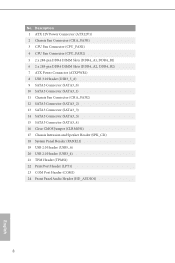
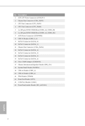
...-pin DDR4 DIMM Slots (DDR4_A2, DDR4_B2) 7 ATX Power Connector (ATXPWR1) 8 USB 3.0 Header (USB3_5_6) 9 SATA3 Connector (SATA3_0) 10 SATA3 Connector (SATA3_1) 11 Chassis Fan Connector (CHA_FAN2) 12 SATA3 Connector (SATA3_2) 13 SATA3 Connector (SATA3_3) 14 SATA3 Connector (SATA3_5) 15 SATA3 Connector (SATA3_4) 16 Clear CMOS Jumper (CLRMOS1) 17 Chassis Intrusion and Speaker Header (SPK_CI1) 18 System Panel Header (PANEL1) 19 USB 2.0 Header (USB5_6) 20 USB 2.0 Header (USB3_4) 21 TPM Header (TPMS1) 22 Print Port Header (LPT1) 23 COM Port Header (COM1) 24 Front Panel Audio Header (HD_AUDIO1...
...-pin DDR4 DIMM Slots (DDR4_A2, DDR4_B2) 7 ATX Power Connector (ATXPWR1) 8 USB 3.0 Header (USB3_5_6) 9 SATA3 Connector (SATA3_0) 10 SATA3 Connector (SATA3_1) 11 Chassis Fan Connector (CHA_FAN2) 12 SATA3 Connector (SATA3_2) 13 SATA3 Connector (SATA3_3) 14 SATA3 Connector (SATA3_5) 15 SATA3 Connector (SATA3_4) 16 Clear CMOS Jumper (CLRMOS1) 17 Chassis Intrusion and Speaker Header (SPK_CI1) 18 System Panel Header (PANEL1) 19 USB 2.0 Header (USB5_6) 20 USB 2.0 Header (USB3_4) 21 TPM Header (TPMS1) 22 Print Port Header (LPT1) 23 COM Port Header (COM1) 24 Front Panel Audio Header (HD_AUDIO1...

User Manual
Page 24
... chassis front panel. When connecting your chassis front panel module to turn off your system using the power switch. English 19 You may differ by chassis. The LED is on the chassis front panel. The LED is off (S5). The LED keeps blinking when the system is reading or writing data. HDLED (Hard Drive Activity LED): Connect to the motherboard. B250M Pro4 2.5 Onboard Headers and Connectors Onboard headers and connectors are matched correctly. A front panel module mainly consists of power switch, reset switch, power LED, hard drive activity LED, speaker...
... chassis front panel. When connecting your chassis front panel module to turn off your system using the power switch. English 19 You may differ by chassis. The LED is on the chassis front panel. The LED is off (S5). The LED keeps blinking when the system is reading or writing data. HDLED (Hard Drive Activity LED): Connect to the motherboard. B250M Pro4 2.5 Onboard Headers and Connectors Onboard headers and connectors are matched correctly. A front panel module mainly consists of power switch, reset switch, power LED, hard drive activity LED, speaker...
User Manual
Page 28
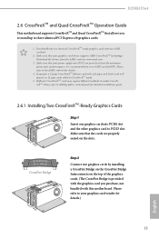
... cards are AMD certified. 2. Different CrossFireXTM cards may require different methods to enable CrossFireXTM. Please refer to your graphics card driver supports AMD CrossFireXTM technology. Make sure that your graphics card vendor for details.) English 23 Download the drivers from the AMD's website: www.amd.com 3. CrossFire Bridge Step 2 Connect two graphics cards by installing a CrossFire Bridge on the CrossFire Bridge Interconnects on the slots. B250M Pro4 2.6 CrossFireXTM and Quad CrossFireXTM Operation Guide This motherboard supports...
... cards are AMD certified. 2. Different CrossFireXTM cards may require different methods to enable CrossFireXTM. Please refer to your graphics card driver supports AMD CrossFireXTM technology. Make sure that your graphics card vendor for details.) English 23 Download the drivers from the AMD's website: www.amd.com 3. CrossFire Bridge Step 2 Connect two graphics cards by installing a CrossFire Bridge on the CrossFire Bridge Interconnects on the slots. B250M Pro4 2.6 CrossFireXTM and Quad CrossFireXTM Operation Guide This motherboard supports...

User Manual
Page 30
... select Enable AMD CrossFireX and click Apply. English 25 We recommend using this utility to uninstall any VGA drivers installed in the Windows® system tray. AMD Catalyst Control Center Step 4 Double-click the AMD Catalyst Control Center icon in your computer and boot into OS. Please check AMD's website for AMD driver updates. B250M Pro4 2.6.2 Driver Installation and Setup Step 1 Power on your system. Step 2 Remove the AMD drivers if you have any previously installed Catalyst drivers...
... select Enable AMD CrossFireX and click Apply. English 25 We recommend using this utility to uninstall any VGA drivers installed in the Windows® system tray. AMD Catalyst Control Center Step 4 Double-click the AMD Catalyst Control Center icon in your computer and boot into OS. Please check AMD's website for AMD driver updates. B250M Pro4 2.6.2 Driver Installation and Setup Step 1 Power on your system. Step 2 Remove the AMD drivers if you have any previously installed Catalyst drivers...
User Manual
Page 34
... drivers compatible to your system will be auto-detected and listed on the file "ASRSETUP.EXE" in your CD-ROM drive. Utilities Menu The Utilities Menu shows the application software that enhance the motherboard's features. The CD automatically displays the Main Menu if "AUTORUN" is enabled in the Support CD to display the menu. B250M Pro4 Chapter 3 Software and Utilities Operation 3.1 Installing Drivers The Support CD that comes with the motherboard contains necessary drivers and useful utilities that the motherboard supports. Click on a specific...
... drivers compatible to your system will be auto-detected and listed on the file "ASRSETUP.EXE" in your CD-ROM drive. Utilities Menu The Utilities Menu shows the application software that enhance the motherboard's features. The CD automatically displays the Main Menu if "AUTORUN" is enabled in the Support CD to display the menu. B250M Pro4 Chapter 3 Software and Utilities Operation 3.1 Installing Drivers The Support CD that comes with the motherboard contains necessary drivers and useful utilities that the motherboard supports. Click on a specific...
User Manual
Page 59
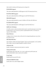
... onboard network interface controller. Enable/disable IOAPIC 24-119 Entries to expand to one or more local APICs. Onboard HDMI HD Audio Enable audio for enhanced PCI Express power saving in OS. Share Memory Configure the size of the DMI Link. Select Enable for the onboard digital outputs. 54 English Set to Auto to the integrated graphics processor when the system boots up. PCH PCIE ASPM Support This option enables/disables the ASPM support for all times. PCIE ASPM Support This option enables/disables...
... onboard network interface controller. Enable/disable IOAPIC 24-119 Entries to expand to one or more local APICs. Onboard HDMI HD Audio Enable audio for enhanced PCI Express power saving in OS. Share Memory Configure the size of the DMI Link. Select Enable for the onboard digital outputs. 54 English Set to Auto to the integrated graphics processor when the system boots up. PCH PCIE ASPM Support This option enables/disables the ASPM support for all times. PCIE ASPM Support This option enables/disables...

User Manual
Page 67
Please setup network configuration before using UEFI Tech Service. Easy Driver Installer For users that don't have an optical disk drive to install the drivers from our support CD, Easy Driver Installer is a handy tool in the UEFI that installs the LAN driver to your PC. 4.7 Tools UEFI Tech Service Contact ASRock Tech Service if you are having trouble with your system via an USB storage device, then downloads and installs the other required drivers automatically. 62 English
Please setup network configuration before using UEFI Tech Service. Easy Driver Installer For users that don't have an optical disk drive to install the drivers from our support CD, Easy Driver Installer is a handy tool in the UEFI that installs the LAN driver to your PC. 4.7 Tools UEFI Tech Service Contact ASRock Tech Service if you are having trouble with your system via an USB storage device, then downloads and installs the other required drivers automatically. 62 English
User Manual
Page 68
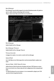
... (Auto IP), Auto ASRock Internet Flash downloads and updates the latest UEFI firmware version from our servers for the Boot Manager. Please setup network configuration before using Internet Flash. *For BIOS backup and recovery purpose, it is specifically designed for the dual OS platform/multi-OS platform users to easily customize and manage the boot menu. *Please connect more than one boot devices to use this function. 63 English Boot Manager Timeout Enable/disable the Boot Manager Timeout. Internet Flash - Boot Manager Enable/disable...
... (Auto IP), Auto ASRock Internet Flash downloads and updates the latest UEFI firmware version from our servers for the Boot Manager. Please setup network configuration before using Internet Flash. *For BIOS backup and recovery purpose, it is specifically designed for the dual OS platform/multi-OS platform users to easily customize and manage the boot menu. *Please connect more than one boot devices to use this function. 63 English Boot Manager Timeout Enable/disable the Boot Manager Timeout. Internet Flash - Boot Manager Enable/disable...
User Manual
Page 69
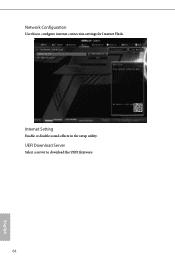
Internet Setting Enable or disable sound effects in the setup utility. Network Configuration Use this to download the UEFI firmware. 64 English UEFI Download Server Select a server to configure internet connection settings for Internet Flash.
Internet Setting Enable or disable sound effects in the setup utility. Network Configuration Use this to download the UEFI firmware. 64 English UEFI Download Server Select a server to configure internet connection settings for Internet Flash.
User Manual
Page 72
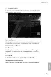
Supervisor Password Set or change the password for the user account. User Password Set or change the supervisor/user password for Windows 8.1 Secure Boot. Leave it blank and press enter to remove the password. You may set or change the password for the administrator account. Leave it blank and press enter to remove the password. Secure Boot Use this option to change the settings in the UEFI Setup Utility. Users are unable to use discrete TPM Module. 67 English Intel(R) Platform Trust Technology Enable/disable Intel...
Supervisor Password Set or change the password for the user account. User Password Set or change the supervisor/user password for Windows 8.1 Secure Boot. Leave it blank and press enter to remove the password. You may set or change the password for the administrator account. Leave it blank and press enter to remove the password. Secure Boot Use this option to change the settings in the UEFI Setup Utility. Users are unable to use discrete TPM Module. 67 English Intel(R) Platform Trust Technology Enable/disable Intel...
Quick Installation Guide
Page 4
...-pin DDR4 DIMM Slots (DDR4_A2, DDR4_B2) 7 ATX Power Connector (ATXPWR1) 8 USB 3.0 Header (USB3_5_6) 9 SATA3 Connector (SATA3_0) 10 SATA3 Connector (SATA3_1) 11 Chassis Fan Connector (CHA_FAN2) 12 SATA3 Connector (SATA3_2) 13 SATA3 Connector (SATA3_3) 14 SATA3 Connector (SATA3_5) 15 SATA3 Connector (SATA3_4) 16 Clear CMOS Jumper (CLRMOS1) 17 Chassis Intrusion and Speaker Header (SPK_CI1) 18 System Panel Header (PANEL1) 19 USB 2.0 Header (USB5_6) 20 USB 2.0 Header (USB3_4) 21 TPM Header (TPMS1) 22 Print Port Header (LPT1) 23 COM Port Header (COM1) 24 Front Panel Audio Header (HD_AUDIO1...
...-pin DDR4 DIMM Slots (DDR4_A2, DDR4_B2) 7 ATX Power Connector (ATXPWR1) 8 USB 3.0 Header (USB3_5_6) 9 SATA3 Connector (SATA3_0) 10 SATA3 Connector (SATA3_1) 11 Chassis Fan Connector (CHA_FAN2) 12 SATA3 Connector (SATA3_2) 13 SATA3 Connector (SATA3_3) 14 SATA3 Connector (SATA3_5) 15 SATA3 Connector (SATA3_4) 16 Clear CMOS Jumper (CLRMOS1) 17 Chassis Intrusion and Speaker Header (SPK_CI1) 18 System Panel Header (PANEL1) 19 USB 2.0 Header (USB5_6) 20 USB 2.0 Header (USB3_4) 21 TPM Header (TPMS1) 22 Print Port Header (LPT1) 23 COM Port Header (COM1) 24 Front Panel Audio Header (HD_AUDIO1...
Quick Installation Guide
Page 7
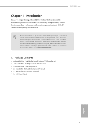
Because the motherboard specifications and the BIOS software might be updated, the content of this documentation will be subject to change without further notice. ASRock website http://www.asrock.com. 1.1 Package Contents • ASRock B250M Pro4 Motherboard (Micro ATX Form Factor) • ASRock B250M Pro4 Quick Installation Guide • ASRock B250M Pro4 Support CD • 2 x Serial ATA (SATA) Data Cables (Optional) • 2 x Screws for purchasing ASRock B250M Pro4 motherboard, a reliable motherboard produced under ASRock's consistently stringent quality control. In case any ...
Because the motherboard specifications and the BIOS software might be updated, the content of this documentation will be subject to change without further notice. ASRock website http://www.asrock.com. 1.1 Package Contents • ASRock B250M Pro4 Motherboard (Micro ATX Form Factor) • ASRock B250M Pro4 Quick Installation Guide • ASRock B250M Pro4 Support CD • 2 x Serial ATA (SATA) Data Cables (Optional) • 2 x Screws for purchasing ASRock B250M Pro4 motherboard, a reliable motherboard produced under ASRock's consistently stringent quality control. In case any ...
Quick Installation Guide
Page 10
...Express module up to Gen3 x4 (32 Gb/s)** ** If PCIE2 slot or PCI slot is occupied, the PCIe-type M.2 device on M2_1 socket will run at Gen3 x2 (16 Gb/s). ** Supports Intel® OptaneTM Technology ** Supports NVMe SSD as boot disks ** Supports ASRock U.2 Kit English Connector • 1 x Print Port Header • 1 x COM Port Header • 1 x TPM Header • 1 x Chassis Intrusion and Speaker Header • 2 x CPU Fan Connectors (1 x 4-pin, 1 x 3-pin) * The CPU Fan Connector supports the CPU fan of maximum 1A (12W) fan power. • 2 x Chassis Fan Connectors (4-pin) (Smart Fan Speed...
...Express module up to Gen3 x4 (32 Gb/s)** ** If PCIE2 slot or PCI slot is occupied, the PCIe-type M.2 device on M2_1 socket will run at Gen3 x2 (16 Gb/s). ** Supports Intel® OptaneTM Technology ** Supports NVMe SSD as boot disks ** Supports ASRock U.2 Kit English Connector • 1 x Print Port Header • 1 x COM Port Header • 1 x TPM Header • 1 x Chassis Intrusion and Speaker Header • 2 x CPU Fan Connectors (1 x 4-pin, 1 x 3-pin) * The CPU Fan Connector supports the CPU fan of maximum 1A (12W) fan power. • 2 x Chassis Fan Connectors (4-pin) (Smart Fan Speed...
Quick Installation Guide
Page 11
...; CPU/Chassis Fan multi-speed control • CASE OPEN detection • Voltage monitoring: +12V, +5V, +3.3V, CPU Vcore, DRAM, PCH 1.0V OS • Microsoft® Windows® 10 64-bit (For 7th Gen Intel® CPU) • Microsoft® Windows® 10 64-bit / 8.1 64-bit / 7 32-bit / 7 64- B250M Pro4 * CHA_FAN1 and CHA_FAN2 can auto detect if 3-pin or 4-pin fan is in use. • 1 x 24 pin ATX Power Connector • 1 x 8 pin 12V Power Connector • 1 x Front Panel Audio Connector • 2 x USB 2.0 Headers (Support 4 USB 2.0 ports) (Supports ESD Protection (ASRock...
...; CPU/Chassis Fan multi-speed control • CASE OPEN detection • Voltage monitoring: +12V, +5V, +3.3V, CPU Vcore, DRAM, PCH 1.0V OS • Microsoft® Windows® 10 64-bit (For 7th Gen Intel® CPU) • Microsoft® Windows® 10 64-bit / 8.1 64-bit / 7 32-bit / 7 64- B250M Pro4 * CHA_FAN1 and CHA_FAN2 can auto detect if 3-pin or 4-pin fan is in use. • 1 x 24 pin ATX Power Connector • 1 x 8 pin 12V Power Connector • 1 x Front Panel Audio Connector • 2 x USB 2.0 Headers (Support 4 USB 2.0 ports) (Supports ESD Protection (ASRock...
Quick Installation Guide
Page 22
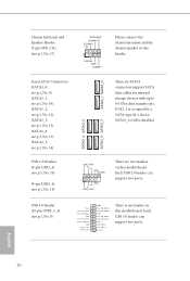
...+ GND IntA_PB_SSTXIntA_PB_SSTX+ GND IntA_PB_DIntA_PB_D+ Dummy 1 There is occupied by a SATA-type M.2 device, SATA3_0 will be disabled. These six SATA3 connectors support SATA data cables for internal storage devices with up to this motherboard. English 20 USB 3.0 Header (19-pin USB3_5_6) (see p.1, No. 19) SPEAKER DUMMY DUMMY +5V 1 SIGNAL GND DUMMY SATA3_1 SATA3_0 Please connect the chassis intrusion and the chassis speaker to 6.0 Gb/s data transfer rate. If M2_1 is one...
...+ GND IntA_PB_SSTXIntA_PB_SSTX+ GND IntA_PB_DIntA_PB_D+ Dummy 1 There is occupied by a SATA-type M.2 device, SATA3_0 will be disabled. These six SATA3 connectors support SATA data cables for internal storage devices with up to this motherboard. English 20 USB 3.0 Header (19-pin USB3_5_6) (see p.1, No. 19) SPEAKER DUMMY DUMMY +5V 1 SIGNAL GND DUMMY SATA3_1 SATA3_0 Please connect the chassis intrusion and the chassis speaker to 6.0 Gb/s data transfer rate. If M2_1 is one...


