

User Manual
Page 4
... 1 1.2 Specifications 2 1.3 Motherboard Layout 6 1.4 I/O Panel 8 Chapter 2 Installation 10 2.1 Installing the CPU 11 2.2 Installing the CPU Fan and Heatsink 14 2.3 Installing Memory Modules (DIMM) 15 2.4 Expansion Slots (PCI Express Slots) 17 2.5 Onboard Headers and Connectors 18 Chapter 3 Software and Utilities Operation 22 3.1 Installing Drivers 22 3.2 ASRock Live Update & APP Shop 23 3.2.1 UI Overview 23 3.2.2 Apps 24 3.2.3 BIOS & Drivers 27 3.2.4 Setting 28 3.3 Enabling USB Ports for Windows® 7 Installation 29 Chapter 4 UEFI SETUP UTILITY 32...
... 1 1.2 Specifications 2 1.3 Motherboard Layout 6 1.4 I/O Panel 8 Chapter 2 Installation 10 2.1 Installing the CPU 11 2.2 Installing the CPU Fan and Heatsink 14 2.3 Installing Memory Modules (DIMM) 15 2.4 Expansion Slots (PCI Express Slots) 17 2.5 Onboard Headers and Connectors 18 Chapter 3 Software and Utilities Operation 22 3.1 Installing Drivers 22 3.2 ASRock Live Update & APP Shop 23 3.2.1 UI Overview 23 3.2.2 Apps 24 3.2.3 BIOS & Drivers 27 3.2.4 Setting 28 3.3 Enabling USB Ports for Windows® 7 Installation 29 Chapter 4 UEFI SETUP UTILITY 32...
User Manual
Page 6
...8226; ASRock B150M-PIO Quick Installation Guide • ASRock B150M-PIO Support CD • 2 x Serial ATA (SATA) Data Cables (Optional) • 1 x I/O Panel Shield • 1 x Screw for purchasing ASRock B150M-PIO motherboard, a reliable motherboard produced under ASRock's consistently stringent quality control. If you require technical support related to quality and endurance. In this motherboard, please visit our website for specific information about the model you for Mini-PCI Express Slot 1 English You may find the latest VGA cards and CPU support list on ASRock's website...
...8226; ASRock B150M-PIO Quick Installation Guide • ASRock B150M-PIO Support CD • 2 x Serial ATA (SATA) Data Cables (Optional) • 1 x I/O Panel Shield • 1 x Screw for purchasing ASRock B150M-PIO motherboard, a reliable motherboard produced under ASRock's consistently stringent quality control. If you require technical support related to quality and endurance. In this motherboard, please visit our website for specific information about the model you for Mini-PCI Express Slot 1 English You may find the latest VGA cards and CPU support list on ASRock's website...

User Manual
Page 8
...; Supports PXE Rear Panel I/O • 1 x PS/2 Mouse Port • 1 x PS/2 Keyboard Port • 1 x DVI-D Port • 2 x USB 2.0 Ports (Supports ESD Protection (ASRock Full Spike Protection))* * ACPI wake-up function is supported on USB01 ports only. • 2 x USB 3.0 Ports (Supports ESD Protection (ASRock Full Spike Protection)) • 1 x RJ-45 LAN Port with max. B150M-PIO • Supports DVI-D with LED (ACT/LINK LED and SPEED LED) • HD Audio Jacks: Line in / Front Speaker / Microphone Storage • 2 x SATA3 6.0 Gb/s Connectors, support NCQ, AHCI and Hot Plug...
...; Supports PXE Rear Panel I/O • 1 x PS/2 Mouse Port • 1 x PS/2 Keyboard Port • 1 x DVI-D Port • 2 x USB 2.0 Ports (Supports ESD Protection (ASRock Full Spike Protection))* * ACPI wake-up function is supported on USB01 ports only. • 2 x USB 3.0 Ports (Supports ESD Protection (ASRock Full Spike Protection)) • 1 x RJ-45 LAN Port with max. B150M-PIO • Supports DVI-D with LED (ACT/LINK LED and SPEED LED) • HD Audio Jacks: Line in / Front Speaker / Microphone Storage • 2 x SATA3 6.0 Gb/s Connectors, support NCQ, AHCI and Hot Plug...

User Manual
Page 9
...8226; Voltage monitoring: +12V, +5V, +3.3V, CPU Vcore, DRAM, PCH 1.0V OS • Microsoft® Windows® 10 64-bit / 8.1 64-bit / 7 32-bit / 7 64- Connector • 1 x TPM Header • 1 x Chassis Intrusion and Speaker Header • 1 x CPU Fan Connector (4-pin) • 1 x Chassis Fan Connector (4-pin) * The CPU Fan Connector supports the CPU fan of maximum 1A (12W) fan power. • 1 x 24 pin ATX Power Connector • 1 x 4 pin 12V Power Connector • 1 x Front Panel Audio Connector • 1 x USB 2.0 Header (Supports 2 USB 2.0 ports) (Supports ESD Protection (ASRock...
...8226; Voltage monitoring: +12V, +5V, +3.3V, CPU Vcore, DRAM, PCH 1.0V OS • Microsoft® Windows® 10 64-bit / 8.1 64-bit / 7 32-bit / 7 64- Connector • 1 x TPM Header • 1 x Chassis Intrusion and Speaker Header • 1 x CPU Fan Connector (4-pin) • 1 x Chassis Fan Connector (4-pin) * The CPU Fan Connector supports the CPU fan of maximum 1A (12W) fan power. • 1 x 24 pin ATX Power Connector • 1 x 4 pin 12V Power Connector • 1 x Front Panel Audio Connector • 1 x USB 2.0 Header (Supports 2 USB 2.0 ports) (Supports ESD Protection (ASRock...

User Manual
Page 11
PS2 Mouse PS2 Keyboard DDR4_A1 (64 bit, 288-pin module) DDR4_B1 (64 bit, 288-pin module) ATXPWR1 1.3 Motherboard Layout PCIE1 CPU_FAN1 CHA_FAN1 Front USB 3.0 ATX12V1 RoHS DVI1 USB 3.0 T: USB1 B: USB2 CMOS Battery USB 2.0 T: USB0 B: USB1 Top: RJ-45 CLRMOS1 USB3_3_4 1 HD_AUDIO1 USB_2_3 1 1 MINI_PCIE1 PCI Express 3.0 Intel B150 TPMS1 1 BIOS B150M-PIO ROM SPK_CI1 PANEL1 PLED PWRBTN 1 1 HDLED RESET Top: LINE IN Center: FRONT Bottom: MIC IN SATA3_2 SATA3_1 English 6
PS2 Mouse PS2 Keyboard DDR4_A1 (64 bit, 288-pin module) DDR4_B1 (64 bit, 288-pin module) ATXPWR1 1.3 Motherboard Layout PCIE1 CPU_FAN1 CHA_FAN1 Front USB 3.0 ATX12V1 RoHS DVI1 USB 3.0 T: USB1 B: USB2 CMOS Battery USB 2.0 T: USB0 B: USB1 Top: RJ-45 CLRMOS1 USB3_3_4 1 HD_AUDIO1 USB_2_3 1 1 MINI_PCIE1 PCI Express 3.0 Intel B150 TPMS1 1 BIOS B150M-PIO ROM SPK_CI1 PANEL1 PLED PWRBTN 1 1 HDLED RESET Top: LINE IN Center: FRONT Bottom: MIC IN SATA3_2 SATA3_1 English 6

User Manual
Page 12
No. Description 1 ATX 12V Power Connector (ATX12V1) 2 CPU Fan Connector (CPU_FAN1) 3 Chassis Fan Connector (CHA_FAN1) 4 2 x 288-pin DDR4 DIMM Slots (DDR4_A1, DDR4_B1) 5 ATX Power Connector (ATXPWR1) 6 SATA3 Connector (SATA3_2) 7 SATA3 Connector (SATA3_1) 8 System Panel Header (PANEL1) 9 Chassis Intrusion and Speaker Header (SPK_CI1) 10 TPM Header (TPMS1) 11 USB 3.0 Header (USB3_3_4) 12 USB 2.0 Header (USB_2_3) 13 Front Panel Audio Header (HD_AUDIO1) B150M-PIO English 7
No. Description 1 ATX 12V Power Connector (ATX12V1) 2 CPU Fan Connector (CPU_FAN1) 3 Chassis Fan Connector (CHA_FAN1) 4 2 x 288-pin DDR4 DIMM Slots (DDR4_A1, DDR4_B1) 5 ATX Power Connector (ATXPWR1) 6 SATA3 Connector (SATA3_2) 7 SATA3 Connector (SATA3_1) 8 System Panel Header (PANEL1) 9 Chassis Intrusion and Speaker Header (SPK_CI1) 10 TPM Header (TPMS1) 11 USB 3.0 Header (USB3_3_4) 12 USB 2.0 Header (USB_2_3) 13 Front Panel Audio Header (HD_AUDIO1) B150M-PIO English 7

User Manual
Page 22
... width graphics cards. mini-PCIe slot: MINI_PCIE1 (Full-size mini-PCIe slot) is used for the card before you start the installation. Please read the documentation of the expansion card and make sure that the power supply is switched off or the power cord is 1 Right Angle PCI Express slot and 1 mini-PCI Express slot on the motherboard. Before installing an expansion card, please make necessary hardware settings for mPCIe and mSATA devices. 17 English B150M-PIO 2.4 Expansion Slots (PCI Express Slots) There...
... width graphics cards. mini-PCIe slot: MINI_PCIE1 (Full-size mini-PCIe slot) is used for the card before you start the installation. Please read the documentation of the expansion card and make sure that the power supply is switched off or the power cord is 1 Right Angle PCI Express slot and 1 mini-PCI Express slot on the motherboard. Before installing an expansion card, please make necessary hardware settings for mPCIe and mSATA devices. 17 English B150M-PIO 2.4 Expansion Slots (PCI Express Slots) There...

User Manual
Page 23
... your chassis front panel module to this header according to the power status indicator on the chassis front panel. A front panel module mainly consists of power switch, reset switch, power LED, hard drive activity LED, speaker and etc. Placing jumper caps over these headers and connectors. Note the positive and negative pins before connecting the cables. Do NOT place jumper caps over the headers and connectors will cause permanent damage to turn off (S5). When connecting your system using the power switch.
... your chassis front panel module to this header according to the power status indicator on the chassis front panel. A front panel module mainly consists of power switch, reset switch, power LED, hard drive activity LED, speaker and etc. Placing jumper caps over these headers and connectors. Note the positive and negative pins before connecting the cables. Do NOT place jumper caps over the headers and connectors will cause permanent damage to turn off (S5). When connecting your system using the power switch.

User Manual
Page 24
These two SATA3 connectors support SATA data cables for connecting audio devices to the front audio panel. Each USB 3.0 header can support two ports. B150M-PIO Chassis Intrusion and Speaker Header (7-pin SPK_CI1) (see p.6, No. 9) Serial ATA3 Connectors (SATA3_1: see p.6, No. 7) (SATA3_2: see p.6, No. 6) SPEAKER DUMMY DUMMY +5V 1 SIGNAL GND DUMMY Please connect the chassis intrusion and the chassis speaker to 6.0 Gb/s data transfer rate. Each USB 2.0 header can support two ports. USB 3.0 Header (19-pin USB3_3_4) (see p.6, No. 11) Vbus IntA_PA_SSRXIntA_PA_SSRX+ GND ...
These two SATA3 connectors support SATA data cables for connecting audio devices to the front audio panel. Each USB 3.0 header can support two ports. B150M-PIO Chassis Intrusion and Speaker Header (7-pin SPK_CI1) (see p.6, No. 9) Serial ATA3 Connectors (SATA3_1: see p.6, No. 7) (SATA3_2: see p.6, No. 6) SPEAKER DUMMY DUMMY +5V 1 SIGNAL GND DUMMY Please connect the chassis intrusion and the chassis speaker to 6.0 Gb/s data transfer rate. Each USB 2.0 header can support two ports. USB 3.0 Header (19-pin USB3_3_4) (see p.6, No. 11) Vbus IntA_PA_SSRXIntA_PA_SSRX+ GND ...

User Manual
Page 25
... motherboard provides a 24-pin ATX power connector. Please follow the instructions in the Realtek Control panel and adjust "Recording Volume". MIC_RET and OUT_RET are for the AC'97 audio panel. Connect Audio_R (RIN) to OUT2_R and Audio_L (LIN) to install your system. 2. E. Chassis Fan Connector FAN_SPEED Please connect fan cables FAN_VOLTAGE_CONTROL (4-pin CHA_FAN1) GND FAN_SPEED_CONTROL to the fan connector and (see p.6, No. 2) FAN_SPEED This motherboard pro- C. To use an AC'97 audio panel, please install it to connect...
... motherboard provides a 24-pin ATX power connector. Please follow the instructions in the Realtek Control panel and adjust "Recording Volume". MIC_RET and OUT_RET are for the AC'97 audio panel. Connect Audio_R (RIN) to OUT2_R and Audio_L (LIN) to install your system. 2. E. Chassis Fan Connector FAN_SPEED Please connect fan cables FAN_VOLTAGE_CONTROL (4-pin CHA_FAN1) GND FAN_SPEED_CONTROL to the fan connector and (see p.6, No. 2) FAN_SPEED This motherboard pro- C. To use an AC'97 audio panel, please install it to connect...

User Manual
Page 27
... auto-detected and listed on the support CD driver page. If the Main Menu does not appear automatically, locate and double click on a specific item then follow the order from top to bottom to your CD-ROM drive. Utilities Menu The Utilities Menu shows the application software that enhance the motherboard's features. Click on the file "ASRSETUP.EXE" in your computer. Drivers Menu The drivers compatible to install those required drivers. To improve Windows 7 compatibility...
... auto-detected and listed on the support CD driver page. If the Main Menu does not appear automatically, locate and double click on a specific item then follow the order from top to bottom to your CD-ROM drive. Utilities Menu The Utilities Menu shows the application software that enhance the motherboard's features. Click on the file "ASRSETUP.EXE" in your computer. Drivers Menu The drivers compatible to install those required drivers. To improve Windows 7 compatibility...
User Manual
Page 28
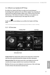
... downloading software applications for your motherboard up to visit the website of the selected news and know more . Click on your desktop to access ASRock Live Update & APP Shop *You need to be connected to the Internet to perform job-related tasks. With ASRock Live Update & APP Shop, you can quickly and easily install various apps and support utilities, such as USB Key, XFast LAN, XFast RAM...
... downloading software applications for your motherboard up to visit the website of the selected news and know more . Click on your desktop to access ASRock Live Update & APP Shop *You need to be connected to the Internet to perform job-related tasks. With ASRock Live Update & APP Shop, you can quickly and easily install various apps and support utilities, such as USB Key, XFast LAN, XFast RAM...

User Manual
Page 34
... have an ODD and PS/2 ports: If there is an optical disc drive, PS/2 ports and PS/2 Keyboard or mouse on their support for the USB ports to function properly, please create a Windows® 7 installation disk with the "Win7 USB Patcher". USB3.0). USB2.0) and only kept the eXtensible Host Controller Interface (XHCI - B150M-PIO 3.3 Enabling USB Ports for Windows® 7 Installation Intel® Braswell and Skylake has removed their motherboard won't work.
... have an ODD and PS/2 ports: If there is an optical disc drive, PS/2 ports and PS/2 Keyboard or mouse on their support for the USB ports to function properly, please create a Windows® 7 installation disk with the "Win7 USB Patcher". USB3.0). USB2.0) and only kept the eXtensible Host Controller Interface (XHCI - B150M-PIO 3.3 Enabling USB Ports for Windows® 7 Installation Intel® Braswell and Skylake has removed their motherboard won't work.
User Manual
Page 35
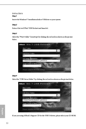
Step 2 Extract the tool (Win7 USB Patcher) and launch it. Step 4 Select the "USB Driver Folder" by clicking the red circle as shown as the picture below . If you are using ASRock's Support CD for the USB 3.0 driver, please select your system. Instructions Step 1 Insert the Windows® 7 installation disk or USB drive to your CD-ROM. 30 English Step 3 Select the "Win7 Folder" from Step1 by clicking the red circle as shown as the picture below .
Step 2 Extract the tool (Win7 USB Patcher) and launch it. Step 4 Select the "USB Driver Folder" by clicking the red circle as shown as the picture below . If you are using ASRock's Support CD for the USB 3.0 driver, please select your system. Instructions Step 1 Insert the Windows® 7 installation disk or USB drive to your CD-ROM. 30 English Step 3 Select the "Win7 Folder" from Step1 by clicking the red circle as shown as the picture below .

User Manual
Page 53
..., isolation, and I/O performance. PCIE ASPM Support This option enables/disables the ASPM support for Directed I/O helps your virtual machine monitor better utilize hardware by improving application compatibility and reliability, and providing additional levels of installed graphic controller. 4.6.2 Chipset Configuration Primary Graphics Adapter Select a primary VGA. VT-d Intel® Virtualization Technology for all PCH PCIE devices. 48 English PCH PCIE ASPM Support This option enables/disables the ASPM support for PCIE1. Top Of Lower Usable Dram Maximum Value of...
..., isolation, and I/O performance. PCIE ASPM Support This option enables/disables the ASPM support for Directed I/O helps your virtual machine monitor better utilize hardware by improving application compatibility and reliability, and providing additional levels of installed graphic controller. 4.6.2 Chipset Configuration Primary Graphics Adapter Select a primary VGA. VT-d Intel® Virtualization Technology for all PCH PCIE devices. 48 English PCH PCIE ASPM Support This option enables/disables the ASPM support for PCIE1. Top Of Lower Usable Dram Maximum Value of...

User Manual
Page 54
... Panel Enable/disable front panel HD audio. If [Power Off] is installed. Share Memory Configure the size of memory that is selected, the system will remain off when the power recovers. If [Power On] is allocated to boot up . B150M-PIO DMI ASPM Support This option enables/disables the control of ASPM on AC/Power Loss Select the power state after a power failure. PCH DMI ASPM Support This option enables/disables the ASPM support for all times. Onboard LAN Enable or disable the onboard network interface controller...
... Panel Enable/disable front panel HD audio. If [Power Off] is installed. Share Memory Configure the size of memory that is selected, the system will remain off when the power recovers. If [Power On] is allocated to boot up . B150M-PIO DMI ASPM Support This option enables/disables the control of ASPM on AC/Power Loss Select the power state after a power failure. PCH DMI ASPM Support This option enables/disables the ASPM support for all times. Onboard LAN Enable or disable the onboard network interface controller...

User Manual
Page 59
... internet curfew or restrict internet access at specified times via an USB storage device, then downloads and installs the other users. 4.7 Tools OMG (Online Management Guard) Administrators are able to modify the system time are having trouble with your system via OMG. You may schedule the starting and ending hours of internet access granted to your PC. Please setup network configuration before using UEFI Tech Service.
... internet curfew or restrict internet access at specified times via an USB storage device, then downloads and installs the other users. 4.7 Tools OMG (Online Management Guard) Administrators are able to modify the system time are having trouble with your system via OMG. You may schedule the starting and ending hours of internet access granted to your PC. Please setup network configuration before using UEFI Tech Service.
User Manual
Page 60
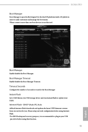
Please setup network configuration before using Internet Flash. *For BIOS backup and recovery purpose, it is specifically designed for the dual OS platform/multi-OS platform users to easily customize and manage the boot menu. *Please connect more than one boot devices to use this function. 55 English DHCP (Auto IP), Auto ASRock Internet Flash downloads and updates the latest UEFI firmware version from our servers for the Boot Manager. Instant Flash Save UEFI files in your UEFI. Timeout Seconds Configure the...
Please setup network configuration before using Internet Flash. *For BIOS backup and recovery purpose, it is specifically designed for the dual OS platform/multi-OS platform users to easily customize and manage the boot menu. *Please connect more than one boot devices to use this function. 55 English DHCP (Auto IP), Auto ASRock Internet Flash downloads and updates the latest UEFI firmware version from our servers for the Boot Manager. Instant Flash Save UEFI files in your UEFI. Timeout Seconds Configure the...

User Manual
Page 61
Network Configuration Use this to download the UEFI firmware. 56 English Internet Setting Enable or disable sound effects in the setup utility. UEFI Download Server Select a server to configure internet connection settings for Internet Flash.
Network Configuration Use this to download the UEFI firmware. 56 English Internet Setting Enable or disable sound effects in the setup utility. UEFI Download Server Select a server to configure internet connection settings for Internet Flash.

User Manual
Page 64
... English User Password Set or change the settings in the UEFI Setup Utility. Secure Boot Use this option to change the password for Windows 8.1 Secure Boot. Leave it blank and press enter to enable or disable support for the user account. Intel(R) Platform Trust Technology Enable/disable Intel PTT in the UEFI Setup Utility. Supervisor Password Set or change the settings in ME. Disable this item to remove the password. B150M-PIO 4.9 Security Screen In this section you may also clear the user password. You may set or change the supervisor/user password...
... English User Password Set or change the settings in the UEFI Setup Utility. Secure Boot Use this option to change the password for Windows 8.1 Secure Boot. Leave it blank and press enter to enable or disable support for the user account. Intel(R) Platform Trust Technology Enable/disable Intel PTT in the UEFI Setup Utility. Supervisor Password Set or change the settings in ME. Disable this item to remove the password. B150M-PIO 4.9 Security Screen In this section you may also clear the user password. You may set or change the supervisor/user password...


