
User Manual
Page 1
All rights reserved. 1 ALiveNF7G-HDready User Manual Version 1.1 Published July 2007 Copyright©2007 ASRock INC.
All rights reserved. 1 ALiveNF7G-HDready User Manual Version 1.1 Published July 2007 Copyright©2007 ASRock INC.

User Manual
Page 2
...that may not be registered trademarks or copyrights of the FCC Rules. Disclaimer: Specifications and information contained in the manual or product. ASRock assumes no event shall ASRock, its directors, officers, employees, or agents be constructed as a commitment by the California Legislature. CALIFORNIA, USA ...ONLY The Lithium battery adopted on this manual may or may appear in this device must accept any defect or error in this manual, ASRock does not provide warranty of any kind, either expressed or implied, including but ...
...that may not be registered trademarks or copyrights of the FCC Rules. Disclaimer: Specifications and information contained in the manual or product. ASRock assumes no event shall ASRock, its directors, officers, employees, or agents be constructed as a commitment by the California Legislature. CALIFORNIA, USA ...ONLY The Lithium battery adopted on this manual may or may appear in this device must accept any defect or error in this manual, ASRock does not provide warranty of any kind, either expressed or implied, including but ...

User Manual
Page 5
... Bracket 5 You may find the latest VGA cards and CPU support lists on ASRock website without notice. Introduction Thank you for purchasing ASRock ALiveNF7G-HDready motherboard, a reliable motherboard produced under ASRock's consistently stringent quality control. In this manual, chapter 1 and 2 contain introduction of this manual occur, the updated version will be updated, the content of the motherboard...
... Bracket 5 You may find the latest VGA cards and CPU support lists on ASRock website without notice. Introduction Thank you for purchasing ASRock ALiveNF7G-HDready motherboard, a reliable motherboard produced under ASRock's consistently stringent quality control. In this manual, chapter 1 and 2 contain introduction of this manual occur, the updated version will be updated, the content of the motherboard...

User Manual
Page 15
... it is locked. Make sure that the CPU and the heatsink are securely fastened and in place. Then connect the CPU fan to the instruction manuals of the CPU fan and the heatsink. 15 For proper installation, please kindly refer to the CPU FAN connector (CPU_FAN1, see Page 12, No. 7). 2.1 CPU...
... it is locked. Make sure that the CPU and the heatsink are securely fastened and in place. Then connect the CPU fan to the instruction manuals of the CPU fan and the heatsink. 15 For proper installation, please kindly refer to the CPU FAN connector (CPU_FAN1, see Page 12, No. 7). 2.1 CPU...
User Manual
Page 22
.... Click "Start" button, select "Settings", and then click "Control Panel". You may pause sometimes. Install "Onboard HDMI HD Audio Driver" from ASRock Support CD to your system. Change the default setting "Speaker" to finish the setting. Step 3: Reboot your system. A. If you install the DVI... available. 22 A. Step 2: Enter Windows® to [Auto]. Set the option "OnBoard HDMI HD Audio" to set up your system manually. Set the option "OnBoard HDMI HD Audio" to the adapter vendor for the chipset adopted on this motherboard and enable HDMI audio function, the...
.... Click "Start" button, select "Settings", and then click "Control Panel". You may pause sometimes. Install "Onboard HDMI HD Audio Driver" from ASRock Support CD to your system. Change the default setting "Speaker" to finish the setting. Step 3: Reboot your system. A. If you install the DVI... available. 22 A. Step 2: Enter Windows® to [Auto]. Set the option "OnBoard HDMI HD Audio" to set up your system manually. Set the option "OnBoard HDMI HD Audio" to the adapter vendor for the chipset adopted on this motherboard and enable HDMI audio function, the...

User Manual
Page 26
... Definition Audio supports Jack Sensing, but the panel wire on the lower right hand taskbar to this header. Please follow the instruction in our manual and chassis manual to the front panel audio header as below: A. If you use AC'97 audio panel, please install it to install your system. 2. Connect Mic_IN...
... Definition Audio supports Jack Sensing, but the panel wire on the lower right hand taskbar to this header. Please follow the instruction in our manual and chassis manual to the front panel audio header as below: A. If you use AC'97 audio panel, please install it to install your system. 2. Connect Mic_IN...

User Manual
Page 29
...white end (3-pin) (C) Please do not connect the white end of HDMI VGA card or other VGA card. Please refer to the VGA card user manual for detailed connection procedures. Install the HDMI VGA card to the wrong connector of HDMI_SPDIF cable to the PCI Express Graphics slot on HDMI_SPDIF cable... card. (There are two white ends (2-pin and 3-pin) on this picture shows the wrong example of connecting HDMI_SPDIF cable to the user manual of HDMI_SPDIF connectors on page 18. Make sure to correctly connect the HDMI_SPDIF cable to the motherboard and the HDMI VGA card according to connect...
...white end (3-pin) (C) Please do not connect the white end of HDMI VGA card or other VGA card. Please refer to the VGA card user manual for detailed connection procedures. Install the HDMI VGA card to the wrong connector of HDMI_SPDIF cable to the PCI Express Graphics slot on HDMI_SPDIF cable... card. (There are two white ends (2-pin and 3-pin) on this picture shows the wrong example of connecting HDMI_SPDIF cable to the user manual of HDMI_SPDIF connectors on page 18. Make sure to correctly connect the HDMI_SPDIF cable to the motherboard and the HDMI VGA card according to connect...

User Manual
Page 32
...pin SATA data cable B. The SATA / SATAII HDD, which are from your dealer or HDD user manual. Please make sure the SATA / SATAII driver is indicated in the product spec on our support website: www.asrock.com 4. Points of SATA / SATAII HDD Hot Plug feature carefully. SATA data cable (Red) B.... Below operation procedure is available on our website: www.asrock.com 2. Please follow below operation guide of attention, before you process the SATA / SATAII HDD Hot Plug, please check below cable accessories ...
...pin SATA data cable B. The SATA / SATAII HDD, which are from your dealer or HDD user manual. Please make sure the SATA / SATAII driver is indicated in the product spec on our support website: www.asrock.com 4. Points of SATA / SATAII HDD Hot Plug feature carefully. SATA data cable (Red) B.... Below operation procedure is available on our website: www.asrock.com 2. Please follow below operation guide of attention, before you process the SATA / SATAII HDD Hot Plug, please check below cable accessories ...

User Manual
Page 41
... Save and Exit Exit v02.54 (C) Copyright 1985-2003, American Megatrends, Inc. AM2 Boost If you will enable ASRock AM2 Boost function, which will be left at the rated frequency/voltage. If Manual, multiplier and voltage will improve the memory performance. CPU Configuration Chipset Configuration ACPI Configuration IDE Configuration PCIPnP Configuration Floppy...
... Save and Exit Exit v02.54 (C) Copyright 1985-2003, American Megatrends, Inc. AM2 Boost If you will enable ASRock AM2 Boost function, which will be left at the rated frequency/voltage. If Manual, multiplier and voltage will improve the memory performance. CPU Configuration Chipset Configuration ACPI Configuration IDE Configuration PCIPnP Configuration Floppy...

User Manual
Page 42
...]. Processor Maximum Voltage It will display Processor Maximum Multiplier for reference. Configuration options: [Disabled] and [Enabled]. Secure Virtual Machine When this option is set to [Manual], you install Windows® VistaTM and want to enable this function, please set this item to [Disable] if above issue occurs. Processor Maximum Multiplier It...
...]. Processor Maximum Voltage It will display Processor Maximum Multiplier for reference. Configuration options: [Disabled] and [Enabled]. Secure Virtual Machine When this option is set to [Manual], you install Windows® VistaTM and want to enable this function, please set this item to [Disable] if above issue occurs. Processor Maximum Multiplier It...

User Manual
Page 43
...Processor Multiplier Processor Voltage [Disabled] [Auto] [200] [100] [Enabled] [Enabled] [Enabled] [Enabled] [Auto] [Enabled] x11.0 2200 MHz 1.400 V [Manual] [x8] [1.500V] If AUTO, multiplier and voltage will be set based on User Selection in Setup. +F1 F9 F10 ESC Select Screen Select Item Change...1985-2003, American Megatrends, Inc. The range of this item. Processor Voltage This item will show when "Multiplier/Voltage Change" is not recommended to [Manual]; Memory Clock This item can set by the code using [Auto]. Configuration options: [Auto], [3T], [4T], [5T] and [6T]. The ...
...Processor Multiplier Processor Voltage [Disabled] [Auto] [200] [100] [Enabled] [Enabled] [Enabled] [Enabled] [Auto] [Enabled] x11.0 2200 MHz 1.400 V [Manual] [x8] [1.500V] If AUTO, multiplier and voltage will be set based on User Selection in Setup. +F1 F9 F10 ESC Select Screen Select Item Change...1985-2003, American Megatrends, Inc. The range of this item. Processor Voltage This item will show when "Multiplier/Voltage Change" is not recommended to [Manual]; Memory Clock This item can set by the code using [Auto]. Configuration options: [Auto], [3T], [4T], [5T] and [6T]. The ...

Quick Installation Guide
Page 4
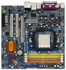
... without further notice. ASRock website http://www.asrock.com 1.1 Package Contents 1 x ASRock ALiveNF7G-HDready Motherboard (Micro ATX Form Factor: 9.6-in x 9.6-in, 24.4 cm x 24.4 cm) 1 x ASRock ALiveNF7G-HDready Quick Installation Guide 2 x ASRock ALiveNF7G-HDready Support CD 1 x Ultra ATA 66/100/133 IDE Ribbon Cable (80-conductor) 1 x 3.5-in the Support CD. This Quick Installation Guide contains introduction of this manual will be available...
... without further notice. ASRock website http://www.asrock.com 1.1 Package Contents 1 x ASRock ALiveNF7G-HDready Motherboard (Micro ATX Form Factor: 9.6-in x 9.6-in, 24.4 cm x 24.4 cm) 1 x ASRock ALiveNF7G-HDready Quick Installation Guide 2 x ASRock ALiveNF7G-HDready Support CD 1 x Ultra ATA 66/100/133 IDE Ribbon Cable (80-conductor) 1 x 3.5-in the Support CD. This Quick Installation Guide contains introduction of this manual will be available...

Quick Installation Guide
Page 12
...CPU corner with the golden triangle matches the socket corner with each other. Then connect the CPU fan to improve heat dissipation. English 12 ASRock ALiveNF7G-HDready Motherboard Lever 90° Up CPU Golden Triangle STEP 1: Lift Up The Socket Lever Socker Corner Small Triangle STEP 2 / STEP 3: ...the heatsink to the CPU FAN connector (CPU_FAN1, see Page 2, No. 7). Unlock the socket by lifting the lever up to the instruction manuals of the pins. Carefully insert the CPU into the socket to dissipate heat. For proper installation, please kindly refer to a 90o angle. ...
...CPU corner with the golden triangle matches the socket corner with each other. Then connect the CPU fan to improve heat dissipation. English 12 ASRock ALiveNF7G-HDready Motherboard Lever 90° Up CPU Golden Triangle STEP 1: Lift Up The Socket Lever Socker Corner Small Triangle STEP 2 / STEP 3: ...the heatsink to the CPU FAN connector (CPU_FAN1, see Page 2, No. 7). Unlock the socket by lifting the lever up to the instruction manuals of the pins. Carefully insert the CPU into the socket to dissipate heat. For proper installation, please kindly refer to a 90o angle. ...

Quick Installation Guide
Page 19
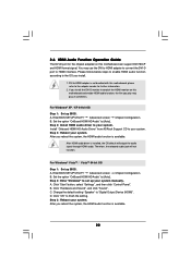
... install. 1. After you reboot the system, the HDMI audio function is available. 19 ASRock ALiveNF7G-HDready Motherboard English For Windows® VistaTM / VistaTM 64-bit OS Step 1:Set up your system manually. A. Enter BIOS SETUP UTILITY Advanced screen Chipset Configuration. B. Set the option "OnBoard ... DVI/HDCP and HDMI format signal. B. Change the default setting "Speaker" to [Auto]. Install "Onboard HDMI HD Audio Driver" from ASRock Support CD to your system. B. Click "OK" to your system. 2.6 HDMI Audio Function Operation Guide The DVI-D port for further information...
... install. 1. After you reboot the system, the HDMI audio function is available. 19 ASRock ALiveNF7G-HDready Motherboard English For Windows® VistaTM / VistaTM 64-bit OS Step 1:Set up your system manually. A. Enter BIOS SETUP UTILITY Advanced screen Chipset Configuration. B. Set the option "OnBoard ... DVI/HDCP and HDMI format signal. B. Change the default setting "Speaker" to [Auto]. Install "Onboard HDMI HD Audio Driver" from ASRock Support CD to your system. B. Click "OK" to your system. 2.6 HDMI Audio Function Operation Guide The DVI-D port for further information...

Quick Installation Guide
Page 23
... audio panel. E. Chassis Fan Connector (3-pin CHA_FAN1) (see p.2 No. 19) This header accommodates several system front panel functions. Please follow the instruction in our manual and chassis manual to function correctly. Connect Audio_R (RIN) to OUT2_R and Audio_L (LIN) to MIC2_L. Enter BIOS Setup Utility. Enter Windows system. For Windows® VistaTM.... English Chassis Speaker Header (4-pin SPEAKER 1) (see p.2 No. 7) 1 2 3 4 Please connect the CPU fan cable to this header. You don't need to the ground pin. 23 ASRock ALiveNF7G-HDready Motherboard B.
... audio panel. E. Chassis Fan Connector (3-pin CHA_FAN1) (see p.2 No. 19) This header accommodates several system front panel functions. Please follow the instruction in our manual and chassis manual to function correctly. Connect Audio_R (RIN) to OUT2_R and Audio_L (LIN) to MIC2_L. Enter BIOS Setup Utility. Enter Windows system. For Windows® VistaTM.... English Chassis Speaker Header (4-pin SPEAKER 1) (see p.2 No. 7) 1 2 3 4 Please connect the CPU fan cable to this header. You don't need to the ground pin. 23 ASRock ALiveNF7G-HDready Motherboard B.
Quick Installation Guide
Page 26
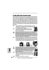
... fan connector of HDMI_SPDIF connectors on the motherboard. Connect the HDMI output connector on this motherboard. Please refer to the user manual of HDMI VGA card or other VGA card. For the pin definition of the HDMI VGA card you install. Please refer...and HDMI_SPDIF cable connectors, please refer to your system. 26 ASRock ALiveNF7G-HDready Motherboard Step 3. Make sure to correctly connect the HDMI_SPDIF cable to the motherboard and the HDMI VGA card according to the VGA card user manual for detailed connection procedures. Step 2. For example, this ...
... fan connector of HDMI_SPDIF connectors on the motherboard. Connect the HDMI output connector on this motherboard. Please refer to the user manual of HDMI VGA card or other VGA card. For the pin definition of the HDMI VGA card you install. Please refer...and HDMI_SPDIF cable connectors, please refer to your system. 26 ASRock ALiveNF7G-HDready Motherboard Step 3. Make sure to correctly connect the HDMI_SPDIF cable to the motherboard and the HDMI VGA card according to the VGA card user manual for detailed connection procedures. Step 2. For example, this ...

Quick Installation Guide
Page 34
.... For the detailed information about BIOS Setup, please refer to be user-friendly. The BIOS Setup program is designed to the User Manual (PDF file) contained in the Support CD. 4. Software Support CD information This motherboard supports various Microsoft® Windows® operating systems...the motherboard stores BIOS Setup Utility. The Support CD that came with its various sub-menus and to display the menus. 34 ASRock ALiveNF7G-HDready Motherboard English 3. It will enhance motherboard features. BIOS Information The Flash Memory on the file "ASSETUP.EXE" from the "BIN...
.... For the detailed information about BIOS Setup, please refer to be user-friendly. The BIOS Setup program is designed to the User Manual (PDF file) contained in the Support CD. 4. Software Support CD information This motherboard supports various Microsoft® Windows® operating systems...the motherboard stores BIOS Setup Utility. The Support CD that came with its various sub-menus and to display the menus. 34 ASRock ALiveNF7G-HDready Motherboard English 3. It will enhance motherboard features. BIOS Information The Flash Memory on the file "ASSETUP.EXE" from the "BIN...

RAID Installation Guide
Page 2
... RAID arrays. SATAII_1 (port 1.0) --> Means controller 1 's first port. WARNING!! SATAII_3 (port 2.0) --> Means controller 2 's first port. For optimal performance, please install identical drives of the "User Manual" in parallel, interleaved stacks. After you can improve the access performance, it will double the data transfer rate of the RAID 0 Disk will improve data...
... RAID arrays. SATAII_1 (port 1.0) --> Means controller 1 's first port. WARNING!! SATAII_3 (port 2.0) --> Means controller 2 's first port. For optimal performance, please install identical drives of the "User Manual" in parallel, interleaved stacks. After you can improve the access performance, it will double the data transfer rate of the RAID 0 Disk will improve data...
