
User Manual
Page 4
... 39 3.1 Introduction 39 3.1.1 BIOS Menu Bar 39 3.1.2 Navigation Keys 40 3.2 Main Screen 40 3.3 Advanced Screen 41 3.3.1 CPU Configuration 41 3.3.2 Chipset Configuration 44 3.3.3 ACPI Configuration 46 3.3.4 IDE Configuration 47 3.3.5 PCIPnP ...
... 39 3.1 Introduction 39 3.1.1 BIOS Menu Bar 39 3.1.2 Navigation Keys 40 3.2 Main Screen 40 3.3 Advanced Screen 41 3.3.1 CPU Configuration 41 3.3.2 Chipset Configuration 44 3.3.3 ACPI Configuration 46 3.3.4 IDE Configuration 47 3.3.5 PCIPnP ...

User Manual
Page 5
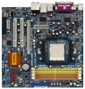
...) 1 x Serial ATA (SATA) HDD Power Cable (Optional) 1 x HDMI_SPDIF Cable (Optional) 1 x ASRock DVI_1394 I/O Shield 1 x COM Port Bracket 5 Because the motherboard specifications and the BIOS software might be available on ASRock website as well. Introduction Thank you for purchasing ASRock ALiveNF7G-HDready motherboard, a reliable motherboard produced under ASRock's consistently stringent quality control. It delivers excellent performance with robust design...
...) 1 x Serial ATA (SATA) HDD Power Cable (Optional) 1 x HDMI_SPDIF Cable (Optional) 1 x ASRock DVI_1394 I/O Shield 1 x COM Port Bracket 5 Because the motherboard specifications and the BIOS software might be available on ASRock website as well. Introduction Thank you for purchasing ASRock ALiveNF7G-HDready motherboard, a reliable motherboard produced under ASRock's consistently stringent quality control. It delivers excellent performance with robust design...

User Manual
Page 7
...64-bit/ VistaTM/VistaTM 64-bit compliant (see CAUTION 11) - 4Mb AMI BIOS - CPU/Chassis FAN connector - 20 pin ATX power connector - 4 pin 12V power connector - AMI Legal BIOS - Drivers, Utilities, AntiVirus Software (Trial Version) - CPU Quiet Fan - Front...(ECP/EPP Support) - 4 x Ready-to-Use USB 2.0 Ports - 1 x IEEE 1394 Port - 1 x RJ-45 Port - Supports jumperfree - CPU Ambient Temperature Sensing - Connector BIOS Feature Support CD Hardware Monitor OS Certifications - 1 x VGA/DVI-D Port (see CAUTION 10) - 1 x ATA133 IDE connector (supports 2 x IDE devices) - 1 x Floppy connector...
...64-bit/ VistaTM/VistaTM 64-bit compliant (see CAUTION 11) - 4Mb AMI BIOS - CPU/Chassis FAN connector - 20 pin ATX power connector - 4 pin 12V power connector - AMI Legal BIOS - Drivers, Utilities, AntiVirus Software (Trial Version) - CPU Quiet Fan - Front...(ECP/EPP Support) - 4 x Ready-to-Use USB 2.0 Ports - 1 x IEEE 1394 Port - 1 x RJ-45 Port - Supports jumperfree - CPU Ambient Temperature Sensing - Connector BIOS Feature Support CD Hardware Monitor OS Certifications - 1 x VGA/DVI-D Port (see CAUTION 10) - 1 x ATA133 IDE connector (supports 2 x IDE devices) - 1 x Floppy connector...
User Manual
Page 8
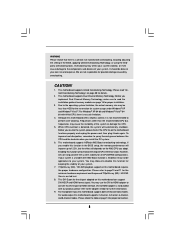
...function will overclock the chipset/CPU reference clock. Frequencies other than 4GB for the reservation for further information. 9. This motherboard supports ASRock AM2 Boost overclocking technology. Enabling this motherboard supports 2-channel, 4-channel, 6-channel, and 8-channel modes. Please refer to the ... to your system is unstable after AM2 Boost function is not bundled with overclocking, including adjusting the setting in the BIOS, applying Untied Overclocking Technology, or using the thirdparty overclocking tools. We are not responsible for all CPU/DRAM configurations....
...function will overclock the chipset/CPU reference clock. Frequencies other than 4GB for the reservation for further information. 9. This motherboard supports ASRock AM2 Boost overclocking technology. Enabling this motherboard supports 2-channel, 4-channel, 6-channel, and 8-channel modes. Please refer to the ... to your system is unstable after AM2 Boost function is not bundled with overclocking, including adjusting the setting in the BIOS, applying Untied Overclocking Technology, or using the thirdparty overclocking tools. We are not responsible for all CPU/DRAM configurations....

User Manual
Page 20
... output support (DVI-D and D-Sub) and the external add-on VGA card is inserted to PCI Express slot. Connect the D-Sub monitor cable to enter BIOS setup. Right click the desktop, choose "Properties", and select the "Settings" tab so that the value you can adjust the parameters of VGA/D-sub. B.... setup of "Share Memory", [Auto], will be designated as appropriate for the diaplay icon identified by the number 2. If you do not adjust the BIOS setup, the default value of your monitors that you have installed the onboard VGA driver and the add-on the I /O panel of the system memory...
... output support (DVI-D and D-Sub) and the external add-on VGA card is inserted to PCI Express slot. Connect the D-Sub monitor cable to enter BIOS setup. Right click the desktop, choose "Properties", and select the "Settings" tab so that the value you can adjust the parameters of VGA/D-sub. B.... setup of "Share Memory", [Auto], will be designated as appropriate for the diaplay icon identified by the number 2. If you do not adjust the BIOS setup, the default value of your monitors that you have installed the onboard VGA driver and the add-on the I /O panel of the system memory...
User Manual
Page 22
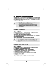
...bundled with this motherboard, please refer to [Auto]. Install "Onboard HDMI HD Audio Driver" from ASRock Support CD to set up your system. Step 3: Reboot your system. Enter BIOS SETUP UTILITY Advanced screen Chipset Configuration. Step 2: Enter Windows® to your system. DVI to... audio driver is available. Click "Hardware and Sound", and click "Sound". B. For Windows® VistaTM / VistaTM 64-bit OS Step 1: Set up BIOS. A. B. C. D. Step 3: Reboot your system manually. A. Click "OK" to your system. If you install the DVI-D monitor instead of the HDMI...
...bundled with this motherboard, please refer to [Auto]. Install "Onboard HDMI HD Audio Driver" from ASRock Support CD to set up your system. Step 3: Reboot your system. Enter BIOS SETUP UTILITY Advanced screen Chipset Configuration. Step 2: Enter Windows® to your system. DVI to... audio driver is available. Click "Hardware and Sound", and click "Sound". B. For Windows® VistaTM / VistaTM 64-bit OS Step 1: Set up BIOS. A. B. C. D. Step 3: Reboot your system manually. A. Click "OK" to your system. If you install the DVI-D monitor instead of the HDMI...

User Manual
Page 23
...p.12, No. 2) +5V +5VSB +5VSB (standby) for 5 seconds. To clear and reset the system parameters to clear the CMOS when you just finish updating the BIOS, you must boot up the system first, and then shut it requires 2 Amp and higher standby current provided by power supply. Note: To select +5VSB.... 2.7 Jumpers Setup The illustration shows how jumpers are "Short" when jumper cap is placed on pins, the jumper is "Short". If you update the BIOS. If no jumper cap is "Open". After waiting for 15 seconds, use a jumper cap to short pin2 and pin3 on pins, the jumper is placed...
...p.12, No. 2) +5V +5VSB +5VSB (standby) for 5 seconds. To clear and reset the system parameters to clear the CMOS when you just finish updating the BIOS, you must boot up the system first, and then shut it requires 2 Amp and higher standby current provided by power supply. Note: To select +5VSB.... 2.7 Jumpers Setup The illustration shows how jumpers are "Short" when jumper cap is placed on pins, the jumper is "Short". If you update the BIOS. If no jumper cap is "Open". After waiting for 15 seconds, use a jumper cap to short pin2 and pin3 on pins, the jumper is placed...

User Manual
Page 26
... and chassis manual to function correctly. Connect Mic_IN (MIC) to Ground (GND). C. Connect Ground (GND) to MIC2_L. You don't need to the ground pin. Enter BIOS Setup Utility. F. Enter Windows system. CPU Fan Connector (4-pin CPU_FAN1) (see p.12 No. 14) PLED+ PLEDPWRBTN# GND 1 DUMMY RESET# GND HDLEDHDLED+ 1 SPEAKER DUMMY DUMMY +5V...
... and chassis manual to function correctly. Connect Mic_IN (MIC) to Ground (GND). C. Connect Ground (GND) to MIC2_L. You don't need to the ground pin. Enter BIOS Setup Utility. F. Enter Windows system. CPU Fan Connector (4-pin CPU_FAN1) (see p.12 No. 14) PLED+ PLEDPWRBTN# GND 1 DUMMY RESET# GND HDLEDHDLED+ 1 SPEAKER DUMMY DUMMY +5V...
User Manual
Page 34
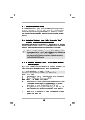
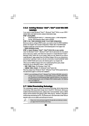
...; 2000 / Windows® XP / Windows® XP 64-bit on the screen, "Generate Serial ATA driver diskette [YN]?", press . 34 Insert the ASRock Support CD into your optical drive to install those required drivers. Before installing Windows® 2000 to your system, your system can work properly. 2.15... Installing Windows® 2000 / XP / XP 64-bit / VistaTM / VistaTM 64-bit Without RAID Functions If you want to include SP4. Enter BIOS SETUP UTILITY Advanced screen IDE Configuration. A. ROM as the boot device. Using SATA / SATAII HDDs with NCQ and Hot Plug functions STEP 1: Set Up...
...; 2000 / Windows® XP / Windows® XP 64-bit on the screen, "Generate Serial ATA driver diskette [YN]?", press . 34 Insert the ASRock Support CD into your optical drive to install those required drivers. Before installing Windows® 2000 to your system, your system can work properly. 2.15... Installing Windows® 2000 / XP / XP 64-bit / VistaTM / VistaTM 64-bit Without RAID Functions If you want to include SP4. Enter BIOS SETUP UTILITY Advanced screen IDE Configuration. A. ROM as the boot device. Using SATA / SATAII HDDs with NCQ and Hot Plug functions STEP 1: Set Up...

User Manual
Page 35
...select A for Windows® XP 64-bit in AHCI mode. Using SATA / SATAII HDDs without NCQ and Hot Plug functions STEP 1: Set Up BIOS. B. Generate RAID Driver diskette for Windows2000/XP 2. At the beginning of Windows® setup, press F6 to the OS you can start to... system will start to continue Please insert a floppy diskette into the floppy diskette. NVIDIA nForce Storage Controller (required) Windows XP/2000 B. Enter BIOS SETUP UTILITY Advanced screen IDE Configuration. Then you install. Set the "SATA Operation Mode" option to the mode you choose and the OS you...
...select A for Windows® XP 64-bit in AHCI mode. Using SATA / SATAII HDDs without NCQ and Hot Plug functions STEP 1: Set Up BIOS. B. Generate RAID Driver diskette for Windows2000/XP 2. At the beginning of Windows® setup, press F6 to the OS you can start to... system will start to continue Please insert a floppy diskette into the floppy diskette. NVIDIA nForce Storage Controller (required) Windows XP/2000 B. Enter BIOS SETUP UTILITY Advanced screen IDE Configuration. Then you install. Set the "SATA Operation Mode" option to the mode you choose and the OS you...

User Manual
Page 36
...® VistaTM 64-bit on your system. NVIDIA® AHCI drivers are in the following path in our Support CD: (There are two ASRock Support CD in the motherboard gift box pack, please choose the one for Windows® VistaTM / VistaTM 64-bit.) .. \ I386 \ AHCI_Vista... If you install. 36 page, please insert the ASRock Support CD into the optical drive to boot your system, and follow the instruction to continue the installation. Enter BIOS SETUP UTILITY Advanced screen IDE Configuration. A. Enter BIOS SETUP UTILITY Advanced screen IDE Configuration. Insert the Windows...
...® VistaTM 64-bit on your system. NVIDIA® AHCI drivers are in the following path in our Support CD: (There are two ASRock Support CD in the motherboard gift box pack, please choose the one for Windows® VistaTM / VistaTM 64-bit.) .. \ I386 \ AHCI_Vista... If you install. 36 page, please insert the ASRock Support CD into the optical drive to boot your system, and follow the instruction to continue the installation. Enter BIOS SETUP UTILITY Advanced screen IDE Configuration. A. Enter BIOS SETUP UTILITY Advanced screen IDE Configuration. Insert the Windows...

User Manual
Page 37
... Windows® 2000 / XP / XP 64-bit With RAID Functions If you need to set up "SATA Operation Mode" to our website in BIOS first. Please make a SATA / SATAII driver diskette by using the Windows RAID installation guide part of Windows® setup, press F6 to check ... 2000 / Windows® XP / Windows® XP 64-bit OS is not ready yet. ASRock website http://www.asrock.com 37 A. B. NVIDIA RAID Driver (required) B. Then, please set RAID configuration. STEP 1: Set Up BIOS. After reading the floppy disk, the drivers will update it to [RAID] in the future. ...
... Windows® 2000 / XP / XP 64-bit With RAID Functions If you need to set up "SATA Operation Mode" to our website in BIOS first. Please make a SATA / SATAII driver diskette by using the Windows RAID installation guide part of Windows® setup, press F6 to check ... 2000 / Windows® XP / Windows® XP 64-bit OS is not ready yet. ASRock website http://www.asrock.com 37 A. B. NVIDIA RAID Driver (required) B. Then, please set RAID configuration. STEP 1: Set Up BIOS. After reading the floppy disk, the drivers will update it to [RAID] in the future. ...
User Manual
Page 38
... is untied during overclocking, FSB enjoys better margin due to fixed PCI / PCIE buses. A. Please refer to the BIOS RAID installation guide part of BIOS setup to set RAID configuration. page, please insert the ASRock Support CD into the optical drive to boot your system, and follow below steps. 2.16.2 Installing Windows®...
... is untied during overclocking, FSB enjoys better margin due to fixed PCI / PCIE buses. A. Please refer to the BIOS RAID installation guide part of BIOS setup to set RAID configuration. page, please insert the ASRock Support CD into the optical drive to boot your system, and follow below steps. 2.16.2 Installing Windows®...

User Manual
Page 39
...restart by pressing the reset button on the menu bar, and then press to configure your screen. 3.1.1 BIOS Menu Bar The top of the screen has a menu bar with its test routines. You may not ...selections: Main To set up the system time/date information Advanced To set up the advanced BIOS features H/W Monitor To display current hardware status Boot To set up the default system device to...set up the computer. Please press during the Power-On-Self-Test (POST) to enter the BIOS SETUP UTILITY after POST, restart the system by pressing + + , or by turning the system off and...
...restart by pressing the reset button on the menu bar, and then press to configure your screen. 3.1.1 BIOS Menu Bar The top of the screen has a menu bar with its test routines. You may not ...selections: Main To set up the system time/date information Advanced To set up the advanced BIOS features H/W Monitor To display current hardware status Boot To set up the default system device to...set up the computer. Please press during the Power-On-Self-Test (POST) to enter the BIOS SETUP UTILITY after POST, restart the system by pressing + + , or by turning the system off and...

User Manual
Page 40
... UTILITY Main Advanced H/W Monitor Boot Security Exit System Overview System Time System Date [17:00:09] [Thu 05/03/2007] BIOS Version : ALiveNF7G-HDready BIOS P1.0 Processor Type : AMD Athlon(tm) 64 Processor 3500+ (64bit supported) Processor Speed : 2200 MHz Microcode Update : 40FF2/0 L1 Cache Size : 128KB L2 Cache Size : ... for the function description of each navigation key. 3.1.2 Navigation Keys Please check the following table for all the settings To save changes and exit the BIOS SETUP UTILITY To jump to the Exit Screen or exit the current screen 3.2 Main Screen When you enter the...
... UTILITY Main Advanced H/W Monitor Boot Security Exit System Overview System Time System Date [17:00:09] [Thu 05/03/2007] BIOS Version : ALiveNF7G-HDready BIOS P1.0 Processor Type : AMD Athlon(tm) 64 Processor 3500+ (64bit supported) Processor Speed : 2200 MHz Microcode Update : 40FF2/0 L1 Cache Size : 128KB L2 Cache Size : ... for the function description of each navigation key. 3.1.2 Navigation Keys Please check the following table for all the settings To save changes and exit the BIOS SETUP UTILITY To jump to the Exit Screen or exit the current screen 3.2 Main Screen When you enter the...

User Manual
Page 41
...on User Selection in this section may set based on page 8 for CPU Select Screen Select Item Enter Go to malfunction. 3.3.1 CPU Configuration BIOS SETUP UTILITY Advanced CPU Configuration AM2 Boost Overclock Mode CPU Frequency (MHz) PCIE Frequency (MHz) CPU/LDT Spread Spectrum PCIE Spread Spectrum SATA ..., Floppy Configuration, SuperIO Configuration, and USB Configuration. Overclock Mode Use this to malfunction. 3.3 Advanced Screen In this section, you will enable ASRock AM2 Boost function, which will be left at the rated frequency/voltage. The default value is [Auto].
...on User Selection in this section may set based on page 8 for CPU Select Screen Select Item Enter Go to malfunction. 3.3.1 CPU Configuration BIOS SETUP UTILITY Advanced CPU Configuration AM2 Boost Overclock Mode CPU Frequency (MHz) PCIE Frequency (MHz) CPU/LDT Spread Spectrum PCIE Spread Spectrum SATA ..., Floppy Configuration, SuperIO Configuration, and USB Configuration. Overclock Mode Use this to malfunction. 3.3 Advanced Screen In this section, you will enable ASRock AM2 Boost function, which will be left at the rated frequency/voltage. The default value is [Auto].

User Manual
Page 43
... Exit v02.54 (C) Copyright 1985-2003, American Megatrends, Inc. Memory Clock This item can set by the code using [Auto]. The default value is [Auto]. BIOS SETUP UTILITY Advanced CPU Configuration AM2 Boost Overclock Mode CPU Frequency (MHz) PCIE Frequency (MHz) CPU/LDT Spread Spectrum PCIE Spread Spectrum SATA Spread Spectrum...
... Exit v02.54 (C) Copyright 1985-2003, American Megatrends, Inc. Memory Clock This item can set by the code using [Auto]. The default value is [Auto]. BIOS SETUP UTILITY Advanced CPU Configuration AM2 Boost Overclock Mode CPU Frequency (MHz) PCIE Frequency (MHz) CPU/LDT Spread Spectrum PCIE Spread Spectrum SATA Spread Spectrum...

User Manual
Page 44
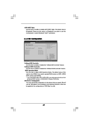
... you select [Auto], the onboard HD Audio will be spread out over banks on the same node, or accross nodes, decreasing access contention. 3.3.2 Chipset Configuration BIOS SETUP UTILITY Advanced Chipset Settings Onboard LAN Onboard 1394 Onboard HDMI HD Audio Onboard HD Audio Front Panel CD-In Share Memory Primary Graphics Adapter...
... you select [Auto], the onboard HD Audio will be spread out over banks on the same node, or accross nodes, decreasing access contention. 3.3.2 Chipset Configuration BIOS SETUP UTILITY Advanced Chipset Settings Onboard LAN Onboard 1394 Onboard HDMI HD Audio Onboard HD Audio Front Panel CD-In Share Memory Primary Graphics Adapter...

User Manual
Page 46
... PCI devices to auto-detect or disable the Suspend-toRAM feature. If you to [Disabled], the function "Repost Video on the system. 46 3.3.3 ACPI Configuration BIOS SETUP UTILITY Advanced ACPI Settings Suspend To RAM Repost Video on STR Resume Away Mode Support Restore on the system from the power-soft-off...
... PCI devices to auto-detect or disable the Suspend-toRAM feature. If you to [Disabled], the function "Repost Video on the system. 46 3.3.3 ACPI Configuration BIOS SETUP UTILITY Advanced ACPI Settings Suspend To RAM Repost Video on STR Resume Away Mode Support Restore on the system from the power-soft-off...
User Manual
Page 47
...Mode Use this item to enable or disable ACPI HPET Table. The default value of "IDE Slave" as the example in NVIDIA BIOS / Windows RAID Utility. IDE Device Configuration You may set this option is [Disabled]. If you want to operate RAID function on ... finish configuring RAID functions in the following instruction, which can be applied to submit Windows® VistaTM certification. 3.3.4 IDE Configuration BIOS SETUP UTILITY Advanced IDE Configuration OnBoard IDE Controller OnBoard SATA Controller SATA Operation Mode IDE Master IDE Slave SATAII_1 SATAII_2 SATAII_3 SATAII_4 [...
...Mode Use this item to enable or disable ACPI HPET Table. The default value of "IDE Slave" as the example in NVIDIA BIOS / Windows RAID Utility. IDE Device Configuration You may set this option is [Disabled]. If you want to operate RAID function on ... finish configuring RAID functions in the following instruction, which can be applied to submit Windows® VistaTM certification. 3.3.4 IDE Configuration BIOS SETUP UTILITY Advanced IDE Configuration OnBoard IDE Controller OnBoard SATA Controller SATA Operation Mode IDE Master IDE Slave SATAII_1 SATAII_2 SATAII_3 SATAII_4 [...


