User Manual
Page 3
... UTILITY 31 3.1 Introduction 31 3.1.1 BIOS Menu Bar 31 3.1.2 Navigation Keys 31 3.2 Main Screen 32 3.3 Advanced Screen 33 3 Installation 12 Pre-installation Precautions 12 2.1 CPU Installation 13 2.2 Installation of CPU Fan and Heatsink 13 2.3 Installation of Memory Modules (DIMM 14 2.4 Expansion Slots (PCI Express, PCI, and HDMR Slots 16 2.5 Easy Multi Monitor Feature...
... UTILITY 31 3.1 Introduction 31 3.1.1 BIOS Menu Bar 31 3.1.2 Navigation Keys 31 3.2 Main Screen 32 3.3 Advanced Screen 33 3 Installation 12 Pre-installation Precautions 12 2.1 CPU Installation 13 2.2 Installation of CPU Fan and Heatsink 13 2.3 Installation of Memory Modules (DIMM 14 2.4 Expansion Slots (PCI Express, PCI, and HDMR Slots 16 2.5 Easy Multi Monitor Feature...
User Manual
Page 4
... System 49 4.2 Support CD Information 49 4.2.1 Running Support CD 49 4.2.2 Drivers Menu 49 4.2.3 Utilities Menu 49 4.2.4 Contact Information 49 APPENDIX: AMD's Cool 'n' QuietTM Technology ...... 50 4 3.3.1 CPU Configuration 34 3.3.2 Chipset Configuration 38 3.3.3 ACPI Configuration 39 3.3.4 IDE Configuration 40 3.3.5 PCIPnP Configuration 42 3.3.6 Floppy Configuration 43 3.3.7 Super IO Configuration 43 3.3.8 USB Configuration 44 3.4 Hardware...
... System 49 4.2 Support CD Information 49 4.2.1 Running Support CD 49 4.2.2 Drivers Menu 49 4.2.3 Utilities Menu 49 4.2.4 Contact Information 49 APPENDIX: AMD's Cool 'n' QuietTM Technology ...... 50 4 3.3.1 CPU Configuration 34 3.3.2 Chipset Configuration 38 3.3.3 ACPI Configuration 39 3.3.4 IDE Configuration 40 3.3.5 PCIPnP Configuration 42 3.3.6 Floppy Configuration 43 3.3.7 Super IO Configuration 43 3.3.8 USB Configuration 44 3.4 Hardware...

User Manual
Page 5
...the motherboard and step-bystep guide to the hardware installation. www.asrock.com/support/index.asp 1.1 Package Contents 1 x ASRock ALiveNF6G-VSTA Motherboard (Micro ATX Form Factor: 9.6-in x 9.6-in, 24.4 cm x 24.4 cm) 1 x ASRock ALiveNF6G-VSTA Quick Installation Guide 1 x ASRock ALiveNF6G-VSTA Support CD 1 x Ultra ATA 66/100/133 IDE Ribbon... performance with robust design conforming to ASRock's commitment to this manual will be updated, the content of the Support CD. You may find the latest VGA cards and CPU support lists on ASRock website without notice. Because the motherboard...
...the motherboard and step-bystep guide to the hardware installation. www.asrock.com/support/index.asp 1.1 Package Contents 1 x ASRock ALiveNF6G-VSTA Motherboard (Micro ATX Form Factor: 9.6-in x 9.6-in, 24.4 cm x 24.4 cm) 1 x ASRock ALiveNF6G-VSTA Quick Installation Guide 1 x ASRock ALiveNF6G-VSTA Support CD 1 x Ultra ATA 66/100/133 IDE Ribbon... performance with robust design conforming to ASRock's commitment to this manual will be updated, the content of the Support CD. You may find the latest VGA cards and CPU support lists on ASRock website without notice. Because the motherboard...
User Manual
Page 6
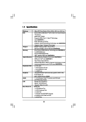
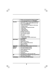
...CAUTION 3) - Supports Hyper-Transport Technology - NVIDIA® GeForce 6100 / nForce 430 or GeForce 6150SE / nForce 430 (see CAUTION 2) - ASRock U-COP (see CAUTION 4) - 4 x DDRII DIMM slots - Speed: 10/100 Ethernet - Socket AM2 for AMDAthlonTM 64FX / 64X2 / ...(2.0 GT/s) - Support DDRII800/667/533 - Boot Failure Guard (B.F.G.) - ASRock AM2 Boost: ASRock Patented Technology to boost memory performance up to -Use USB 2.0 Ports - 1 x RJ-45 Port 6 Realtek PHY RTL8201CL - 1.2 Specifications Platform CPU Chipset Memory Hybrid Booster Expansion Slot Graphics Audio LAN Rear Panel I /O ...
...CAUTION 3) - Supports Hyper-Transport Technology - NVIDIA® GeForce 6100 / nForce 430 or GeForce 6150SE / nForce 430 (see CAUTION 2) - ASRock U-COP (see CAUTION 4) - 4 x DDRII DIMM slots - Speed: 10/100 Ethernet - Socket AM2 for AMDAthlonTM 64FX / 64X2 / ...(2.0 GT/s) - Support DDRII800/667/533 - Boot Failure Guard (B.F.G.) - ASRock AM2 Boost: ASRock Patented Technology to boost memory performance up to -Use USB 2.0 Ports - 1 x RJ-45 Port 6 Realtek PHY RTL8201CL - 1.2 Specifications Platform CPU Chipset Memory Hybrid Booster Expansion Slot Graphics Audio LAN Rear Panel I /O ...
User Manual
Page 7
... 6 USB 2.0 ports) (see CAUTION 10) - 1 x ATA133 IDE connector (supports 2 x IDE devices) - 1 x Floppy connector - 1 x DeskExpress Hot Plug Detection header - 1 x Game header - 1 x COM port header - 1 x HDMI_SPDIF header - CPU Ambient Temperature Sensing - Chassis Temperature Sensing - Voltage Monitoring: +12V, +5V, +3.3V, Vcore - Microsoft® Windows® 2000/XP/XP Media Center/XP 64-bit/ VistaTM...
... 6 USB 2.0 ports) (see CAUTION 10) - 1 x ATA133 IDE connector (supports 2 x IDE devices) - 1 x Floppy connector - 1 x DeskExpress Hot Plug Detection header - 1 x Game header - 1 x COM port header - 1 x HDMI_SPDIF header - CPU Ambient Temperature Sensing - Chassis Temperature Sensing - Voltage Monitoring: +12V, +5V, +3.3V, Vcore - Microsoft® Windows® 2000/XP/XP Media Center/XP 64-bit/ VistaTM...
User Manual
Page 8
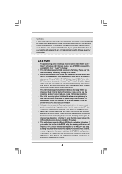
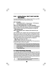
... of the system or damage the CPU. 7. If you install NVIDIA® driver with 91.63 version or above under Windows system. Frequencies other than 4GB for the reservation for proper installation. 5. This motherboard supports ASRock AM2 Boost overclocking technology. However, ...we can not guarantee the system stability for possible damage caused by overclocking. We are not responsible for all CPU/DRAM configurations. While CPU overheat is enabled, it is not recommended...
... of the system or damage the CPU. 7. If you install NVIDIA® driver with 91.63 version or above under Windows system. Frequencies other than 4GB for the reservation for proper installation. 5. This motherboard supports ASRock AM2 Boost overclocking technology. However, ...we can not guarantee the system stability for possible damage caused by overclocking. We are not responsible for all CPU/DRAM configurations. While CPU overheat is enabled, it is not recommended...

User Manual
Page 9
... to adjust your SATAII hard disk drive to submit Windows® VistaTM Premium and Basic logo, please follow the below table for proper connection. 10. CPU Memory Sempron 2800+ 512MB x 2 Dual Channel (Premium) 512MB Single Channel (Basic) 256MB x 2 Dual Channel (Basic) * If you use onboard VGA with ...use external graphics card on this motherboard and plan to SATAII mode. Before installing SATAII hard disk to Premium Discrete requirement at http://www.asrock.com 9 If you plan to use onboard VGA with total system memory size 512MB and plan to submit Windows® VistaTM Basic logo,...
... to adjust your SATAII hard disk drive to submit Windows® VistaTM Premium and Basic logo, please follow the below table for proper connection. 10. CPU Memory Sempron 2800+ 512MB x 2 Dual Channel (Premium) 512MB Single Channel (Basic) 256MB x 2 Dual Channel (Basic) * If you use onboard VGA with ...use external graphics card on this motherboard and plan to SATAII mode. Before installing SATAII hard disk to Premium Discrete requirement at http://www.asrock.com 9 If you plan to use onboard VGA with total system memory size 512MB and plan to submit Windows® VistaTM Basic logo,...
User Manual
Page 10
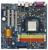
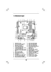
...; 1.4 Motherboard Layout 1 2 34 5 67 8 24.4cm (9.6-in) PS2 Keyboard PS2 Mouse 1 PS2_USB_PW1 ATX12V1 CPU_FAN1 IR1 1 9 Super I/O GAME1 1 Dual Core CPU Dual Channel PARALLEL PORT DDRII_3 (64/72 bit, 240F-pSinBm8o0d0ule) DDRII_4 (64/72 bit, 240-pin module) DDRII_2 (64/72 bit, 240-pin module) DDRII_1... 28 27 Top: LINE IN Center: FRONT Bottom: MIC IN LAN PHY CD1 AUDIO CODEC HDMI_SPDIF1 1 1 HD_AUDIO1 PCIE1 PCI EXPRESS RAID ALiveNF6G-VSTA PCI1 PCI2 PCIE2 7.1CH HD HDMR1 CMOS BATTERY CLRCMOS1 1 NVIDIA GeForce 6100 / nForce 430 or GeForce 6150SE / nForce 430 Chipset RoHS ...
...; 1.4 Motherboard Layout 1 2 34 5 67 8 24.4cm (9.6-in) PS2 Keyboard PS2 Mouse 1 PS2_USB_PW1 ATX12V1 CPU_FAN1 IR1 1 9 Super I/O GAME1 1 Dual Core CPU Dual Channel PARALLEL PORT DDRII_3 (64/72 bit, 240F-pSinBm8o0d0ule) DDRII_4 (64/72 bit, 240-pin module) DDRII_2 (64/72 bit, 240-pin module) DDRII_1... 28 27 Top: LINE IN Center: FRONT Bottom: MIC IN LAN PHY CD1 AUDIO CODEC HDMI_SPDIF1 1 1 HD_AUDIO1 PCIE1 PCI EXPRESS RAID ALiveNF6G-VSTA PCI1 PCI2 PCIE2 7.1CH HD HDMR1 CMOS BATTERY CLRCMOS1 1 NVIDIA GeForce 6100 / nForce 430 or GeForce 6150SE / nForce 430 Chipset RoHS ...
User Manual
Page 13
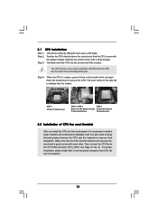
...to indicate that it is locked. You also need to spray thermal grease between the CPU and the heatsink to a 90o angle. For proper installation, please kindly refer to the instruction manuals of CPU Fan and Heatsink After you push down the socket lever to avoid bending of the ...pins. Unlock the socket by lifting the lever up to improve heat dissipation. Step 4. Step 3. Carefully insert the CPU into the socket to secure the CPU. DO NOT force the CPU into the socket until it is in one correct orientation. U90°pLever CSneorckeCtPeanUGgldiTenrol STEP 1: Lift Up The Socket ...
...to indicate that it is locked. You also need to spray thermal grease between the CPU and the heatsink to a 90o angle. For proper installation, please kindly refer to the instruction manuals of CPU Fan and Heatsink After you push down the socket lever to avoid bending of the ...pins. Unlock the socket by lifting the lever up to improve heat dissipation. Step 4. Step 3. Carefully insert the CPU into the socket to secure the CPU. DO NOT force the CPU into the socket until it is in one correct orientation. U90°pLever CSneorckeCtPeanUGgldiTenrol STEP 1: Lift Up The Socket ...
User Manual
Page 21
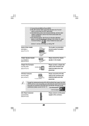
...taskbar to the ground pin. You don't need to [Enabled]. Enter BIOS Setup Utility. Enter Advanced Settings, and then select Chipset Configuration. CPU Fan Connector (4-pin CPU_FAN1) (see p.10 No. 32) Please connect an ATX power supply to this connector and match the black wire... Pin 1-3 Connected 3-Pin Fan Installation ATX Power Connector (20-pin ATXPWR1) (see p.10 No. 5) 4 3 2 1 GND +12V CPU_FAN_SPEED FAN_SPEED_CONTROL Please connect the CPU fan cable to the ground pin. C. System Panel Header (9-pin PANEL1) (see p.10 No. 18) Chassis Speaker Header (4-pin SPEAKER 1) (see p.10 No. ...
...taskbar to the ground pin. You don't need to [Enabled]. Enter BIOS Setup Utility. Enter Advanced Settings, and then select Chipset Configuration. CPU Fan Connector (4-pin CPU_FAN1) (see p.10 No. 32) Please connect an ATX power supply to this connector and match the black wire... Pin 1-3 Connected 3-Pin Fan Installation ATX Power Connector (20-pin ATXPWR1) (see p.10 No. 5) 4 3 2 1 GND +12V CPU_FAN_SPEED FAN_SPEED_CONTROL Please connect the CPU fan cable to the ground pin. C. System Panel Header (9-pin PANEL1) (see p.10 No. 18) Chassis Speaker Header (4-pin SPEAKER 1) (see p.10 No. ...
User Manual
Page 30
...(create, convert, delete, or rebuild) RAID functions on SATA / SATAII HDDs, you apply Untied Overclocking Technology. 30 Before you start to [CPU, PCIE, Async.]. Please refer to the BIOS RAID installation guide part of BIOS setup to set RAID configuration. A. STEP 2: Use "RAID Installation... refer to continue the installation. Then, please set up "SATA Operation Mode" to fixed PCI / PCIE buses. page, please insert the ASRock Support CD into the optical drive to load the NVIDIA® RAID drivers. If you install Windows® VistaTM / Windows® VistaTM ...
...(create, convert, delete, or rebuild) RAID functions on SATA / SATAII HDDs, you apply Untied Overclocking Technology. 30 Before you start to [CPU, PCIE, Async.]. Please refer to the BIOS RAID installation guide part of BIOS setup to set RAID configuration. A. STEP 2: Use "RAID Installation... refer to continue the installation. Then, please set up "SATA Operation Mode" to fixed PCI / PCIE buses. page, please insert the ASRock Support CD into the optical drive to load the NVIDIA® RAID drivers. If you install Windows® VistaTM / Windows® VistaTM ...

User Manual
Page 33
... Chipset Configuration ACPI Configuration IDE Configuration PCIPnP Configuration Floppy Configuration SuperIO Configuration USB Configuration Options for the following items: CPU Configuration, Chipset Configuration, ACPI Configuration, IDE Configuration, PCIPnP Configuration, Floppy Configuration, SuperIO Configuration, and USB Configuration... H/W Monitor Boot Security Exit Advanced Settings WARNING : Setting wrong values in this section, you may set the configurations for CPU Select Screen Select Item Enter Go to Sub Screen F1 General Help F9 Load Defaults F10 Save and Exit ESC Exit v02...
... Chipset Configuration ACPI Configuration IDE Configuration PCIPnP Configuration Floppy Configuration SuperIO Configuration USB Configuration Options for the following items: CPU Configuration, Chipset Configuration, ACPI Configuration, IDE Configuration, PCIPnP Configuration, Floppy Configuration, SuperIO Configuration, and USB Configuration... H/W Monitor Boot Security Exit Advanced Settings WARNING : Setting wrong values in this section, you may set the configurations for CPU Select Screen Select Item Enter Go to Sub Screen F1 General Help F9 Load Defaults F10 Save and Exit ESC Exit v02...

User Manual
Page 34
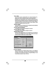
... will be set to [Enabled] as default. Overclock Mode Use this option to adjust PCIE frequency. Configuration options: [Auto], [CPU, PCIE, Sync.] and [CPU, PCIE, Async.]. Boot Failure Guard Enable or disable the feature of Boot Failure Guard. PCIE Spread Spectrum This feature will improve the... is [100]. Configuration options: [Disabled] and [Enabled]. CPU Frequency (MHz) Use this option to [Enabled], you set this option to select Overclock Mode. Please refer to [Enabled] as default. AM2 Boost If you will enable ASRock AM2 Boost function, which will be left at the rated ...
... will be set to [Enabled] as default. Overclock Mode Use this option to adjust PCIE frequency. Configuration options: [Auto], [CPU, PCIE, Sync.] and [CPU, PCIE, Async.]. Boot Failure Guard Enable or disable the feature of Boot Failure Guard. PCIE Spread Spectrum This feature will improve the... is [100]. Configuration options: [Disabled] and [Enabled]. CPU Frequency (MHz) Use this option to [Enabled], you set this option to select Overclock Mode. Please refer to [Enabled] as default. AM2 Boost If you will enable ASRock AM2 Boost function, which will be left at the rated ...
User Manual
Page 35
...Cool 'n' Quiet Use this item to [Manual]; If you adopt on this motherboard. Dual Core Support This item will show if you may reduce CPU voltage and memory frequency, and lead to [Enabled]. The default value is [Auto]. If Manual, multiplier and voltage will be left at the ...[Auto] by default. If it will display Processor Maximum Multiplier for system stability. Processor Maximum Multiplier It will be set based on the CPU you install Windows® VistaTM and want to enable this function, please set this item to system stability or compatibility issue with some memory...
...Cool 'n' Quiet Use this item to [Manual]; If you adopt on this motherboard. Dual Core Support This item will show if you may reduce CPU voltage and memory frequency, and lead to [Enabled]. The default value is [Auto]. If Manual, multiplier and voltage will be left at the ...[Auto] by default. If it will display Processor Maximum Multiplier for system stability. Processor Maximum Multiplier It will be set based on the CPU you install Windows® VistaTM and want to enable this function, please set this item to system stability or compatibility issue with some memory...
User Manual
Page 36
... [6CLK]. TRTP Use this option is not recommended to adjust the value of this item to adjust the means of the value depends on the CPU you adopt on this to adjust TRCD values. Flexibility Option The default value of the standard values as listed: [200 MHz (DDRII 400)], [266 MHz...
... [6CLK]. TRTP Use this option is not recommended to adjust the value of this item to adjust the means of the value depends on the CPU you adopt on this to adjust TRCD values. Flexibility Option The default value of the standard values as listed: [200 MHz (DDRII 400)], [266 MHz...

User Manual
Page 38
...HD Audio Front Panel Controller CD-In Share Memory Primary Graphics Adapter [Enabled] [Auto] [Auto] [Enabled] [Auto] [PCI] CPU-NB Link Speed CPU-NB Kink Width DRAM Voltage [Auto] [Auto] [Auto] To set share memory feature. OnBoard LAN This allows you plan to ...] or [Disabled] for video card. Configuration options: [Auto], [16MB], [32MB], [64MB], [128MB], and [256MB]. The default value of multiple video controllers. CPU - NB Link Speed This feature allows you to NB link frequency. Configuration options: [PCI], [Onboard] and [PCI Express]. Configuration options: [Auto], [8 bit],...
...HD Audio Front Panel Controller CD-In Share Memory Primary Graphics Adapter [Enabled] [Auto] [Auto] [Enabled] [Auto] [PCI] CPU-NB Link Speed CPU-NB Kink Width DRAM Voltage [Auto] [Auto] [Auto] To set share memory feature. OnBoard LAN This allows you plan to ...] or [Disabled] for video card. Configuration options: [Auto], [16MB], [32MB], [64MB], [128MB], and [256MB]. The default value of multiple video controllers. CPU - NB Link Speed This feature allows you to NB link frequency. Configuration options: [PCI], [Onboard] and [PCI Express]. Configuration options: [Auto], [8 bit],...
User Manual
Page 45
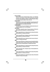
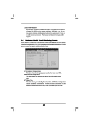
etc. if there is [Disabled]. BIOS SETUP UTILITY Main Advanced H/W Monitor Boot Security Exit Hardware Health Event Monitoring CPU Ambient Temperature CPU Internal Temperature M / B Temperature CPU Fan Speed Chassis Fan Speed Vcore + 3.30V + 5.00V + 12.00V CPU Quiet Fan : 42 C / 107 F : 52 C / 125 F : 31 C / 87 F : 2833 RPM : N/A : 1.532 V ... allows you to monitor the status of the hardware on your system, including the parameters of the CPU temperature, motherboard temperature, CPU fan speed, chassis fan speed, and the critical voltage. You are allowed to identify the temperature of...
etc. if there is [Disabled]. BIOS SETUP UTILITY Main Advanced H/W Monitor Boot Security Exit Hardware Health Event Monitoring CPU Ambient Temperature CPU Internal Temperature M / B Temperature CPU Fan Speed Chassis Fan Speed Vcore + 3.30V + 5.00V + 12.00V CPU Quiet Fan : 42 C / 107 F : 52 C / 125 F : 31 C / 87 F : 2833 RPM : N/A : 1.532 V ... allows you to monitor the status of the hardware on your system, including the parameters of the CPU temperature, motherboard temperature, CPU fan speed, chassis fan speed, and the critical voltage. You are allowed to identify the temperature of...

Quick Installation Guide
Page 2
...Connector (COM1) 16 Primary SATAII Connector (SATAII_1, Red) 2 ASRock ALiveNF6G-VSTA Motherboard Motherboard Layout English 1 PS2_USB_PW1 Jumper 17 USB 2.0 Header (USB6_7, Blue) 2 ATX 12V Power Connector (ATX12V1) 18 System Panel Header (PANEL1) 3 CPU Heatsink Retention Module 19 USB 2.0 Header (USB8_9, Blue) ...4 AM2 940-Pin CPU Socket 20 USB 2.0 Header (USB4_5, Blue) 5 CPU Fan Connector (CPU_FAN1) 21 Chassis Speaker Header (SPEAKER 1) 6 2 x 240...
...Connector (COM1) 16 Primary SATAII Connector (SATAII_1, Red) 2 ASRock ALiveNF6G-VSTA Motherboard Motherboard Layout English 1 PS2_USB_PW1 Jumper 17 USB 2.0 Header (USB6_7, Blue) 2 ATX 12V Power Connector (ATX12V1) 18 System Panel Header (PANEL1) 3 CPU Heatsink Retention Module 19 USB 2.0 Header (USB8_9, Blue) ...4 AM2 940-Pin CPU Socket 20 USB 2.0 Header (USB4_5, Blue) 5 CPU Fan Connector (CPU_FAN1) 21 Chassis Speaker Header (SPEAKER 1) 6 2 x 240...

Quick Installation Guide
Page 4
... as well. You may find the latest VGA cards and CPU support lists on ASRock website without notice. www.asrock.com/support/index.asp 1.1 Package Contents 1 x ASRock ALiveNF6G-VSTA Motherboard (Micro ATX Form Factor: 9.6-in x 9.6-in, 24.4 cm x 24.4 cm) 1 x ASRock ALiveNF6G-VSTA Quick Installation Guide 1 x ASRock ALiveNF6G-VSTA Support CD 1 x Ultra ATA 66/100/133 IDE Ribbon Cable (80-conductor) 1 x 3.5-in...
... as well. You may find the latest VGA cards and CPU support lists on ASRock website without notice. www.asrock.com/support/index.asp 1.1 Package Contents 1 x ASRock ALiveNF6G-VSTA Motherboard (Micro ATX Form Factor: 9.6-in x 9.6-in, 24.4 cm x 24.4 cm) 1 x ASRock ALiveNF6G-VSTA Quick Installation Guide 1 x ASRock ALiveNF6G-VSTA Support CD 1 x Ultra ATA 66/100/133 IDE Ribbon Cable (80-conductor) 1 x 3.5-in...

Quick Installation Guide
Page 5
... HD Audio (ALC888 Audio Codec) - Realtek PHY RTL8201CL - Support DDRII800/667/533 - Pixel Shader 3.0 - Max. ASRock AM2 Boost: ASRock Patented Technology to boost memory performance up to -Use USB 2.0 Ports - 1 x RJ-45 Port 5 ASRock ALiveNF6G-VSTA Motherboard English 1.2 Specifications Platform CPU Chipset Memory Hybrid Booster Expansion Slot Graphics Audio LAN Rear Panel I /O - 1 x PS/2 Mouse Port - 1 x PS...
... HD Audio (ALC888 Audio Codec) - Realtek PHY RTL8201CL - Support DDRII800/667/533 - Pixel Shader 3.0 - Max. ASRock AM2 Boost: ASRock Patented Technology to boost memory performance up to -Use USB 2.0 Ports - 1 x RJ-45 Port 5 ASRock ALiveNF6G-VSTA Motherboard English 1.2 Specifications Platform CPU Chipset Memory Hybrid Booster Expansion Slot Graphics Audio LAN Rear Panel I /O - 1 x PS/2 Mouse Port - 1 x PS...


