User Manual
Page 6
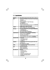
... 'n' QuietTM Technology (see CAUTION 3) - NVIDIA® GeForce 6100 / nForce 430 or GeForce 6150SE / nForce 430 (see CAUTION 1) - ASRock AM2 Boost: ASRock Patented Technology to boost memory performance up to -Use USB 2.0 Ports - 1 x RJ-45 Port 6 Max. Supports Wake-On-LAN HD...FSB 1000 MHz (2.0 GT/s) - capacity: 8GB (see CAUTION 6) - CPU Frequency Stepless Control (see CAUTION 5) - Realtek PHY RTL8201CL - Supports Untied Overclocking Technology (see CAUTION 7) - Boot Failure Guard (B.F.G.) - Max. Socket AM2 for AMDAthlonTM 64FX / 64X2 / X2 / 64 and Sempron Processors -...
... 'n' QuietTM Technology (see CAUTION 3) - NVIDIA® GeForce 6100 / nForce 430 or GeForce 6150SE / nForce 430 (see CAUTION 1) - ASRock AM2 Boost: ASRock Patented Technology to boost memory performance up to -Use USB 2.0 Ports - 1 x RJ-45 Port 6 Max. Supports Wake-On-LAN HD...FSB 1000 MHz (2.0 GT/s) - capacity: 8GB (see CAUTION 6) - CPU Frequency Stepless Control (see CAUTION 5) - Realtek PHY RTL8201CL - Supports Untied Overclocking Technology (see CAUTION 7) - Boot Failure Guard (B.F.G.) - Max. Socket AM2 for AMDAthlonTM 64FX / 64X2 / X2 / 64 and Sempron Processors -...
User Manual
Page 10
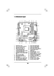
...28 27 Top: LINE IN Center: FRONT Bottom: MIC IN LAN PHY CD1 AUDIO CODEC HDMI_SPDIF1 1 1 HD_AUDIO1 PCIE1 PCI EXPRESS RAID ALiveNF6G-VSTA PCI1 PCI2 PCIE2 7.1CH HD HDMR1 CMOS BATTERY CLRCMOS1 1 NVIDIA GeForce 6100 / nForce 430 or GeForce 6150SE / nForce 430 Chipset ... Header (USB6_7, Blue) 2 ATX 12V Power Connector (ATX12V1) 18 System Panel Header (PANEL1) 3 CPU Heatsink Retention Module 19 USB 2.0 Header (USB8_9, Blue) 4 AM2 940-Pin CPU Socket 20 USB 2.0 Header (USB4_5, Blue) 5 CPU Fan Connector (CPU_FAN1) 21 Chassis Speaker Header (SPEAKER 1) 6 2 x 240-pin DDRII DIMM Slots ...
...28 27 Top: LINE IN Center: FRONT Bottom: MIC IN LAN PHY CD1 AUDIO CODEC HDMI_SPDIF1 1 1 HD_AUDIO1 PCIE1 PCI EXPRESS RAID ALiveNF6G-VSTA PCI1 PCI2 PCIE2 7.1CH HD HDMR1 CMOS BATTERY CLRCMOS1 1 NVIDIA GeForce 6100 / nForce 430 or GeForce 6150SE / nForce 430 Chipset ... Header (USB6_7, Blue) 2 ATX 12V Power Connector (ATX12V1) 18 System Panel Header (PANEL1) 3 CPU Heatsink Retention Module 19 USB 2.0 Header (USB8_9, Blue) 4 AM2 940-Pin CPU Socket 20 USB 2.0 Header (USB4_5, Blue) 5 CPU Fan Connector (CPU_FAN1) 21 Chassis Speaker Header (SPEAKER 1) 6 2 x 240-pin DDRII DIMM Slots ...
User Manual
Page 13
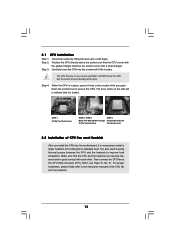
.... 13 For proper installation, please kindly refer to avoid bending of CPU Fan and Heatsink After you push down the socket lever to the CPU FAN connector (CPU_FAN1, see Page 10, No. 5). Carefully insert the CPU into this motherboard, it fits in place, press it is necessary... that it firmly on the side tab to a 90o angle. Position the CPU directly above the socket such that the CPU and the heatsink are securely fastened and in one correct orientation. Step 4. The CPU fits only in good contact with a small triangle. U90°pLever CSneorckeCtPeanUGgldiTenrol...
.... 13 For proper installation, please kindly refer to avoid bending of CPU Fan and Heatsink After you push down the socket lever to the CPU FAN connector (CPU_FAN1, see Page 10, No. 5). Carefully insert the CPU into this motherboard, it fits in place, press it is necessary... that it firmly on the side tab to a 90o angle. Position the CPU directly above the socket such that the CPU and the heatsink are securely fastened and in one correct orientation. Step 4. The CPU fits only in good contact with a small triangle. U90°pLever CSneorckeCtPeanUGgldiTenrol...

Quick Installation Guide
Page 2
...Header (USB6_7, Blue) 2 ATX 12V Power Connector (ATX12V1) 18 System Panel Header (PANEL1) 3 CPU Heatsink Retention Module 19 USB 2.0 Header (USB8_9, Blue) 4 AM2 940-Pin CPU Socket 20 USB 2.0 Header (USB4_5, Blue) 5 CPU Fan Connector (CPU_FAN1) 21 Chassis Speaker Header (SPEAKER 1) 6 2 x 240-pin DDRII DIMM Slots...ATXPWR1) 15 Chassis Fan Connector (CHA_FAN1) 33 Serial Port Connector (COM1) 16 Primary SATAII Connector (SATAII_1, Red) 2 ASRock ALiveNF6G-VSTA Motherboard Yellow) (SATAII_2, Red) 7 2 x 240-pin DDRII DIMM Slots 23 NVIDIA Single Chip (Dual Channel B: DDRII_3, DDRII_4;
...Header (USB6_7, Blue) 2 ATX 12V Power Connector (ATX12V1) 18 System Panel Header (PANEL1) 3 CPU Heatsink Retention Module 19 USB 2.0 Header (USB8_9, Blue) 4 AM2 940-Pin CPU Socket 20 USB 2.0 Header (USB4_5, Blue) 5 CPU Fan Connector (CPU_FAN1) 21 Chassis Speaker Header (SPEAKER 1) 6 2 x 240-pin DDRII DIMM Slots...ATXPWR1) 15 Chassis Fan Connector (CHA_FAN1) 33 Serial Port Connector (COM1) 16 Primary SATAII Connector (SATAII_1, Red) 2 ASRock ALiveNF6G-VSTA Motherboard Yellow) (SATAII_2, Red) 7 2 x 240-pin DDRII DIMM Slots 23 NVIDIA Single Chip (Dual Channel B: DDRII_3, DDRII_4;

Quick Installation Guide
Page 5
Socket AM2 for AMDAthlonTM 64FX / 64X2 / X2 / 64 and Sempron Processors - FSB 1000 MHz (2.0 GT/s) - capacity: 8GB (see CAUTION 2) - Boot Failure Guard (B.F.G.) - Integrated NVIDIA® GeForce6-class graphics DX9.0 VGA - Supports Wake-On-LAN HD 8CH I /O - 1.2 Specifications Platform CPU... ASRock ALiveNF6G-VSTA Motherboard English Max. Realtek PHY RTL8201CL - Supports AMD's Cool 'n' QuietTM Technology (see CAUTION 3) - NVIDIA® GeForce 6100 / nForce 430 or GeForce 6150SE / nForce 430 (see CAUTION 1) - Dual Channel DDRII Memory Technology (see CAUTION 6) - CPU ...
Socket AM2 for AMDAthlonTM 64FX / 64X2 / X2 / 64 and Sempron Processors - FSB 1000 MHz (2.0 GT/s) - capacity: 8GB (see CAUTION 2) - Boot Failure Guard (B.F.G.) - Integrated NVIDIA® GeForce6-class graphics DX9.0 VGA - Supports Wake-On-LAN HD 8CH I /O - 1.2 Specifications Platform CPU... ASRock ALiveNF6G-VSTA Motherboard English Max. Realtek PHY RTL8201CL - Supports AMD's Cool 'n' QuietTM Technology (see CAUTION 3) - NVIDIA® GeForce 6100 / nForce 430 or GeForce 6150SE / nForce 430 (see CAUTION 1) - Dual Channel DDRII Memory Technology (see CAUTION 6) - CPU ...
Quick Installation Guide
Page 9
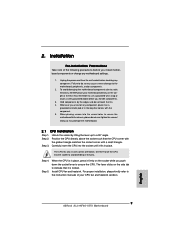
... with a small triangle. The lever clicks on a grounded antstatic pad or in place. English 9 ASRock ALiveNF6G-VSTA Motherboard Installation Pre-installation Precautions Take note of the pins. Step 3. Unlock the socket by the edges and do so may damage the motherboard. 2.1 CPU Installation Step 1. To avoid damaging the motherboard components due to indicate that the...
... with a small triangle. The lever clicks on a grounded antstatic pad or in place. English 9 ASRock ALiveNF6G-VSTA Motherboard Installation Pre-installation Precautions Take note of the pins. Step 3. Unlock the socket by the edges and do so may damage the motherboard. 2.1 CPU Installation Step 1. To avoid damaging the motherboard components due to indicate that the...


