RAID Installation Guide
Page 1
NVIDIA Windows RAID Installation Guide 8 2.1 NVIDIA Windows RAID Installation Guide for Windows 2000 / XP / XP 64-bit Users 8 2.2 NVIDIA Windows RAID Installation Guide for Windows Vista / Vista 64-bit Users 18 1 NVIDIA RAID Installation Guide 1. NVIDIA BIOS RAID Installation Guide 2 1.1 Introduction to RAID 2 1.2 RAID Configurations Precautions 3 1.3 Create Disk Array 4 2.
NVIDIA Windows RAID Installation Guide 8 2.1 NVIDIA Windows RAID Installation Guide for Windows 2000 / XP / XP 64-bit Users 8 2.2 NVIDIA Windows RAID Installation Guide for Windows Vista / Vista 64-bit Users 18 1 NVIDIA RAID Installation Guide 1. NVIDIA BIOS RAID Installation Guide 2 1.1 Introduction to RAID 2 1.2 RAID Configurations Precautions 3 1.3 Create Disk Array 4 2.

RAID Installation Guide
Page 2
... configure RAID. 1. Please refer to create RAID arrays. SATAII_2 (port 1.1) --> Means controller 1 's second port. For optimal performance, please install identical drives of using NVRAID RAID Utility for you to the SATA / SATAII HDDs amount you make a SATA / SATAII driver diskette, press to... interleaved stacks. SATAII_4 (port 2.1) --> Means controller 2 's second port. 1.1 Introduction to read and write data in our support CD or "Quick Installation Guide", you may choose to use RAID 0, RAID 1, RAID 0+1, JBOD, or RAID 5 function with four SATA / SATAII ports, you can improve ...
... configure RAID. 1. Please refer to create RAID arrays. SATAII_2 (port 1.1) --> Means controller 1 's second port. For optimal performance, please install identical drives of using NVRAID RAID Utility for you to the SATA / SATAII HDDs amount you make a SATA / SATAII driver diskette, press to... interleaved stacks. SATAII_4 (port 2.1) --> Means controller 2 's second port. 1.1 Introduction to read and write data in our support CD or "Quick Installation Guide", you may choose to use RAID 0, RAID 1, RAID 0+1, JBOD, or RAID 5 function with four SATA / SATAII ports, you can improve ...

RAID Installation Guide
Page 8
...according to configure and manage RAID functions. Please follow the instructions below screen appears. 8 After you finish the driver installation, you install. 2.1 NVIDIA Windows RAID Installation Guide for you to configure RAID functions by clicking on Start → Programs → NVIDIA Corporation → ...our support CD. For Windows 2000 / XP / XP 64-bit and Windows Vista / Vista 64-bit, there are different installation procedures. Please enter NVRAIDMAN by using NVIDIAMAN under Windows environment. 2. Enter NVRAIDMAN RAID driver is an instruction for Windows 2000 /...
...according to configure and manage RAID functions. Please follow the instructions below screen appears. 8 After you finish the driver installation, you install. 2.1 NVIDIA Windows RAID Installation Guide for you to configure RAID functions by clicking on Start → Programs → NVIDIA Corporation → ...our support CD. For Windows 2000 / XP / XP 64-bit and Windows Vista / Vista 64-bit, there are different installation procedures. Please enter NVRAIDMAN by using NVIDIAMAN under Windows environment. 2. Enter NVRAIDMAN RAID driver is an instruction for Windows 2000 /...
RAID Installation Guide
Page 9
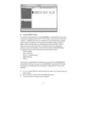
... : A. Please refer to create RAID 0 (Striping). RAID 0+1: Stripe Mirroring - If you how to use RAID 0, RAID 1, or JBOD function with two SATA / SATAII ports, you install. Boot to the steps of using NVRAIDMAN for example to show you plan to use are as below: - The RAID items which may be mentioned...
... : A. Please refer to create RAID 0 (Striping). RAID 0+1: Stripe Mirroring - If you how to use RAID 0, RAID 1, or JBOD function with two SATA / SATAII ports, you install. Boot to the steps of using NVRAIDMAN for example to show you plan to use are as below: - The RAID items which may be mentioned...
RAID Installation Guide
Page 18
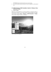
Please enter Storage by clicking on the desktop.) Then, the below screen appears. 18 After you finish the driver installation, you can create, delete, or rebuild any RAID array. NVRAIDMAN window indicates that the array is also a "Storage" shortcut on Start → Programs → NVIDIA ... in our support CD. Enter Storage RAID driver is built in NVIDIA ALL in one driver provided in a short period of time. 2.2 NVIDIA Windows RAID Installation Guide for Windows Vista / Vista 64-bit Users A.
Please enter Storage by clicking on the desktop.) Then, the below screen appears. 18 After you finish the driver installation, you can create, delete, or rebuild any RAID array. NVRAIDMAN window indicates that the array is also a "Storage" shortcut on Start → Programs → NVIDIA ... in our support CD. Enter Storage RAID driver is built in NVIDIA ALL in one driver provided in a short period of time. 2.2 NVIDIA Windows RAID Installation Guide for Windows Vista / Vista 64-bit Users A.
User Manual
Page 3
... 31 3.1.1 BIOS Menu Bar 31 3.1.2 Navigation Keys 31 3.2 Main Screen 32 3.3 Advanced Screen 33 3 Installation 12 Pre-installation Precautions 12 2.1 CPU Installation 13 2.2 Installation of CPU Fan and Heatsink 13 2.3 Installation of Memory Modules (DIMM 14 2.4 Expansion Slots (PCI Express, PCI, and HDMR Slots 16 2.5 Easy...Connection Guide 23 2.9 SATAII Hard Disk Setup Guide 24 2.10 Serial ATA (SATA) / Serial ATAII (SATAII) Hard Disks Installation 25 2.11 Hot Plug and Hot Swap Functions for Windows® VistaTM Premium and Basic Logo 9 1.4 Motherboard Layout 10 1.5 HD 8CH I/O ...
... 31 3.1.1 BIOS Menu Bar 31 3.1.2 Navigation Keys 31 3.2 Main Screen 32 3.3 Advanced Screen 33 3 Installation 12 Pre-installation Precautions 12 2.1 CPU Installation 13 2.2 Installation of CPU Fan and Heatsink 13 2.3 Installation of Memory Modules (DIMM 14 2.4 Expansion Slots (PCI Express, PCI, and HDMR Slots 16 2.5 Easy...Connection Guide 23 2.9 SATAII Hard Disk Setup Guide 24 2.10 Serial ATA (SATA) / Serial ATAII (SATAII) Hard Disks Installation 25 2.11 Hot Plug and Hot Swap Functions for Windows® VistaTM Premium and Basic Logo 9 1.4 Motherboard Layout 10 1.5 HD 8CH I/O ...
User Manual
Page 4
Software Support 49 4.1 Install Operating System 49 4.2 Support CD Information 49 4.2.1 Running Support CD 49 4.2.2 Drivers Menu 49 4.2.3 Utilities Menu 49 4.2.4 Contact Information 49 APPENDIX: AMD's Cool 'n' QuietTM Technology ...... ...
Software Support 49 4.1 Install Operating System 49 4.2 Support CD Information 49 4.2.1 Running Support CD 49 4.2.2 Drivers Menu 49 4.2.3 Utilities Menu 49 4.2.4 Contact Information 49 APPENDIX: AMD's Cool 'n' QuietTM Technology ...... ...

User Manual
Page 5
... for specific information about the model you require technical support related to quality and endurance. www.asrock.com/support/index.asp 1.1 Package Contents 1 x ASRock ALiveNF6G-VSTA Motherboard (Micro ATX Form Factor: 9.6-in x 9.6-in, 24.4 cm x 24.4 cm) 1 x ASRock ALiveNF6G-VSTA Quick Installation Guide 1 x ASRock ALiveNF6G-VSTA Support CD 1 x Ultra ATA 66/100/133 IDE Ribbon Cable (80-conductor) 1 x 3.5-in Floppy Drive...
... for specific information about the model you require technical support related to quality and endurance. www.asrock.com/support/index.asp 1.1 Package Contents 1 x ASRock ALiveNF6G-VSTA Motherboard (Micro ATX Form Factor: 9.6-in x 9.6-in, 24.4 cm x 24.4 cm) 1 x ASRock ALiveNF6G-VSTA Quick Installation Guide 1 x ASRock ALiveNF6G-VSTA Support CD 1 x Ultra ATA 66/100/133 IDE Ribbon Cable (80-conductor) 1 x 3.5-in Floppy Drive...
User Manual
Page 8
... cord, then plug it may affect your system stability, or even cause damage to enable AMD's Cool 'n' QuietTM technology. 2. Please read the installation guide of this function will automatically shutdown. Frequencies other than 4GB for the reservation for keeping the stability of your system. 8 However, the difference.... Overclocking may not be done at your system. For power-saving's sake, it is not recommended to the same chipset. Before you install the PC system. 8. This motherboard supports ASRock AM2 Boost overclocking technology. Enabling this motherboard. 4.
... cord, then plug it may affect your system stability, or even cause damage to enable AMD's Cool 'n' QuietTM technology. 2. Please read the installation guide of this function will automatically shutdown. Frequencies other than 4GB for the reservation for keeping the stability of your system. 8 However, the difference.... Overclocking may not be done at your system. For power-saving's sake, it is not recommended to the same chipset. Before you install the PC system. 8. This motherboard supports ASRock AM2 Boost overclocking technology. Enabling this motherboard. 4.

User Manual
Page 9
... you use external graphics card on this motherboard supports both stereo and mono modes. Before installing SATAII hard disk to 64MB. 9. You can also connect SATA hard disk to Premium Discrete requirement at http://www.asrock.com 9 If you plan to use onboard VGA with total system memory size 512MB and plan...
... you use external graphics card on this motherboard supports both stereo and mono modes. Before installing SATAII hard disk to 64MB. 9. You can also connect SATA hard disk to Premium Discrete requirement at http://www.asrock.com 9 If you plan to use onboard VGA with total system memory size 512MB and plan...

User Manual
Page 12
Installation This is detached from the wall socket before touching any motherboard settings. To avoid damaging the motherboard components due to the motherboard, peripherals, and/or ... to secure the motherboard to ensure that comes with the component. 5. 2. Also remember to use a grounded wrist strap or touch a safety grounded object before you install the motherboard, study the configuration of your motherboard directly on a grounded antistatic pad or in , 24.4 cm x 24.4 cm) motherboard. Before you...
Installation This is detached from the wall socket before touching any motherboard settings. To avoid damaging the motherboard components due to the motherboard, peripherals, and/or ... to secure the motherboard to ensure that comes with the component. 5. 2. Also remember to use a grounded wrist strap or touch a safety grounded object before you install the motherboard, study the configuration of your motherboard directly on a grounded antistatic pad or in , 24.4 cm x 24.4 cm) motherboard. Before you...
User Manual
Page 13
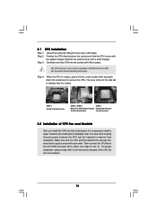
...STEP 1: Lift Up The Socket Lever STEP 2 / STEP 3: STEP 4: Match The CPU Golden Triangle Push Down And Lock To The Socket Corner The Socket Lever 2.2 Installation of CPU Fan and Heatsink After you push down the socket lever to indicate that the CPU corner with the golden triangle matches the socket... corner with each other. 2.1 CPU Installation Step 1. The CPU fits only in place, press it firmly on the side tab to secure the CPU. You also need to spray thermal ...
...STEP 1: Lift Up The Socket Lever STEP 2 / STEP 3: STEP 4: Match The CPU Golden Triangle Push Down And Lock To The Socket Corner The Socket Lever 2.2 Installation of CPU Fan and Heatsink After you push down the socket lever to indicate that the CPU corner with the golden triangle matches the socket... corner with each other. 2.1 CPU Installation Step 1. The CPU fits only in place, press it firmly on the side tab to secure the CPU. You also need to spray thermal ...

User Manual
Page 14
...Channel B (DDRII_3 and DDRII_4; If a pair of memory modules is unable to the Dual Channel Memory Configuration Table below. In other words, install them in all four slots. Orange slots; Dual Channel Memory Configurations DDRII_1 DDRII_2 DDRII_3 DDRII_4 (Yellow Slot) (Yellow Slot) (Orange Slot) (... in all four slots. 1. This motherboard also allows you always need to activate the Dual Channel Memory Technology. 3. 2.3 Installation of Memory Modules (DIMM) This motherboard provides four 240-pin DDRII (Double Data Rate II) DIMM slots, and supports Dual Channel Memory ...
...Channel B (DDRII_3 and DDRII_4; If a pair of memory modules is unable to the Dual Channel Memory Configuration Table below. In other words, install them in all four slots. Orange slots; Dual Channel Memory Configurations DDRII_1 DDRII_2 DDRII_3 DDRII_4 (Yellow Slot) (Yellow Slot) (Orange Slot) (... in all four slots. 1. This motherboard also allows you always need to activate the Dual Channel Memory Technology. 3. 2.3 Installation of Memory Modules (DIMM) This motherboard provides four 240-pin DDRII (Double Data Rate II) DIMM slots, and supports Dual Channel Memory ...

User Manual
Page 15
Installing a DIMM Please make sure to the motherboard and the DIMM if you force the DIMM into the slot until the retaining clips at incorrect orientation. ...
Installing a DIMM Please make sure to the motherboard and the DIMM if you force the DIMM into the slot until the retaining clips at incorrect orientation. ...

User Manual
Page 16
...with v.92 Modem functionality. PCIE2 (PCIE x1 slot) is shared with x1 lane width cards, such as Gigabit LAN card, SATA2 card, etc. Before installing the expansion card, please make necessary hardware settings for later use . Align the card connector with screws. 16 Step 4. Keep the screws for the card...HDMR slot to use . Fasten the card to the chassis with the slot and press firmly until the card is unplugged. you start the installation. Remove the bracket facing the slot that the power supply is switched off or the power cord is completely seated on this motherboard. PCI ...
...with v.92 Modem functionality. PCIE2 (PCIE x1 slot) is shared with x1 lane width cards, such as Gigabit LAN card, SATA2 card, etc. Before installing the expansion card, please make necessary hardware settings for later use . Align the card connector with screws. 16 Step 4. Keep the screws for the card...HDMR slot to use . Fasten the card to the chassis with the slot and press firmly until the card is unplugged. you start the installation. Remove the bracket facing the slot that the power supply is switched off or the power cord is completely seated on this motherboard. PCI ...

User Manual
Page 17
...function when the add-on VGA card is inserted to the VGA/D-Sub connector of the add-on PCI Express VGA card, you have installed the onboard VGA driver already, there is less than the total capability of Multi Monitor feature. Repeat steps C through E for the ...parameters of "Share Memory", [Auto], will be designated as appropriate for details. 2. Please refer to PCIE1 (PCIE x16 slot). Install the onboard VGA driver to install it again. 5. When you install other Windows® OS, the item names and operation procedures may be your card, one , two, and three. 17 ...
...function when the add-on VGA card is inserted to the VGA/D-Sub connector of the add-on PCI Express VGA card, you have installed the onboard VGA driver already, there is less than the total capability of Multi Monitor feature. Repeat steps C through E for the ...parameters of "Share Memory", [Auto], will be designated as appropriate for details. 2. Please refer to PCIE1 (PCIE x16 slot). Install the onboard VGA driver to install it again. 5. When you install other Windows® OS, the item names and operation procedures may be your card, one , two, and three. 17 ...
User Manual
Page 20
... three USB 2.0 headers on the chassis must support HDA to OUT2_L. 20 B. This connector allows you use AC'97 audio panel, please install it to receive stereo audio input from sound sources such as below: A. Connect Audio_R (RIN) to OUT2_R and Audio_L (LIN) to function... 26) GND PRESENCE# MIC_RET OUT_RET 1 OUT2_L J_SENSE OUT2_R MIC2_R MIC2_L This is an interface for ASRock DeskExpress. Please follow the instruction in our manual and chassis manual to MIC2_L. Connect Mic_IN (MIC) to install your system. 2. Each USB 2.0 header can support two USB 2.0 ports. (9-pin USB6_7) ...
... three USB 2.0 headers on the chassis must support HDA to OUT2_L. 20 B. This connector allows you use AC'97 audio panel, please install it to receive stereo audio input from sound sources such as below: A. Connect Audio_R (RIN) to OUT2_R and Audio_L (LIN) to function... 26) GND PRESENCE# MIC_RET OUT_RET 1 OUT2_L J_SENSE OUT2_R MIC2_R MIC2_L This is an interface for ASRock DeskExpress. Please follow the instruction in our manual and chassis manual to MIC2_L. Connect Mic_IN (MIC) to install your system. 2. Each USB 2.0 header can support two USB 2.0 ports. (9-pin USB6_7) ...
User Manual
Page 21
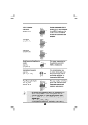
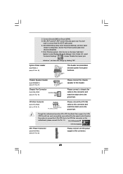
... 4-Pin CPU fan (Quiet Fan) support, the 3-Pin CPU fan still can work successfully even without the fan speed control function. Pin 1-3 Connected 3-Pin Fan Installation ATX Power Connector (20-pin ATXPWR1) (see p.10 No. 32) Please connect an ATX power supply to connect them for HD audio panel only. Connect...
... 4-Pin CPU fan (Quiet Fan) support, the 3-Pin CPU fan still can work successfully even without the fan speed control function. Pin 1-3 Connected 3-Pin Fan Installation ATX Power Connector (20-pin ATXPWR1) (see p.10 No. 32) Please connect an ATX power supply to connect them for HD audio panel only. Connect...

User Manual
Page 22
... GAME1) (see p.10 No. 9) Serial port Header (9-pin COM1) (see p.10 No.33) HDMI_SPDIF Header (3-pin HDMI_SPDIF1) (see p.10 No. 2) Please note that it is installed.
... GAME1) (see p.10 No. 9) Serial port Header (9-pin COM1) (see p.10 No.33) HDMI_SPDIF Header (3-pin HDMI_SPDIF1) (see p.10 No. 2) Please note that it is installed.
User Manual
Page 23
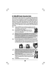
... slot on page 16. 2.8 HDMI_SPDIF Header Connection Guide HDMI (High-Definition Multi-media Interface) is equipped with a HDMI_SPDIF header. Install the HDMI VGA card to the VGA card user manual for detailed connection procedures. Please choose the appropriate white end according to this...to the HDMI_SPDIF connector of HDMI VGA card vendor. For the pin definition of HDMI_SPDIF connectors on HDMI VGA card, please refer to the installation guide on this motherboard and the HDMI VGA card. Incorrect connection may be damaged. white end (2-pin) (B) white end (3-pin) (C)...
... slot on page 16. 2.8 HDMI_SPDIF Header Connection Guide HDMI (High-Definition Multi-media Interface) is equipped with a HDMI_SPDIF header. Install the HDMI VGA card to the VGA card user manual for detailed connection procedures. Please choose the appropriate white end according to this...to the HDMI_SPDIF connector of HDMI VGA card vendor. For the pin definition of HDMI_SPDIF connectors on HDMI VGA card, please refer to the installation guide on this motherboard and the HDMI VGA card. Incorrect connection may be damaged. white end (2-pin) (B) white end (3-pin) (C)...


