RAID Installation Guide
Page 2
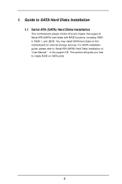
1. This section will guide you how to SATA Hard Disks Installation 1.1 Serial ATA (SATA) Hard Disks Installation This motherboard adopts nVidia nForce3 chipset that supports Serial ATA (SATA) hard disks with RAID functions, including RAID 0, RAID 1, and JBOD. Guide to create RAID on this motherboard for internal storage devices. For SATA installation guide, please refer to Serial ATA (SATA) Hard Disks Installation of "U ser Manual " in the support CD. You may install SATA hard disks on SATA ports. 2
1. This section will guide you how to SATA Hard Disks Installation 1.1 Serial ATA (SATA) Hard Disks Installation This motherboard adopts nVidia nForce3 chipset that supports Serial ATA (SATA) hard disks with RAID functions, including RAID 0, RAID 1, and JBOD. Guide to create RAID on this motherboard for internal storage devices. For SATA installation guide, please refer to Serial ATA (SATA) Hard Disks Installation of "U ser Manual " in the support CD. You may install SATA hard disks on SATA ports. 2

User Manual
Page 1
ALiveNF4G-DVI User Manual Version 1.1 Published August 2006 Copyright©2006 ASRock INC. All rights reserved. 1
ALiveNF4G-DVI User Manual Version 1.1 Published August 2006 Copyright©2006 ASRock INC. All rights reserved. 1

User Manual
Page 2
... errors or omissions that may not be constructed as a commitment by the purchaser for backup purpose, without written consent of ASRock Inc. Copyright Notice: No part of this manual. ASRock Website: http://www.asrock.com 2 Operation is subject to the implied warranties or conditions of their respective companies, and are furnished for a particular purpose...
... errors or omissions that may not be constructed as a commitment by the purchaser for backup purpose, without written consent of ASRock Inc. Copyright Notice: No part of this manual. ASRock Website: http://www.asrock.com 2 Operation is subject to the implied warranties or conditions of their respective companies, and are furnished for a particular purpose...
User Manual
Page 5
... manual, chapter 1 and 2 contain introduction of the Support CD. Chapter 3 and 4 contain the configuration guide to BIOS setup and information of the motherboard and step-bystep guide to quality and endurance. Introduction Thank you for purchasing ASRock ALiveNF4G-DVI motherboard, a reliable motherboard produced under ASRock's consistently stringent quality control. ASRock website http://www.asrock.com 1.1 Package Contents 1 x ASRock ALiveNF4G-DVI...
... manual, chapter 1 and 2 contain introduction of the Support CD. Chapter 3 and 4 contain the configuration guide to BIOS setup and information of the motherboard and step-bystep guide to quality and endurance. Introduction Thank you for purchasing ASRock ALiveNF4G-DVI motherboard, a reliable motherboard produced under ASRock's consistently stringent quality control. ASRock website http://www.asrock.com 1.1 Package Contents 1 x ASRock ALiveNF4G-DVI...

User Manual
Page 13
... installation, please kindly refer to improve heat dissipation. Step 3. You also need to spray thermal grease between the CPU and the heatsink to the instruction manuals of CPU Fan and Heatsink After you push down the socket lever to indicate that the CPU corner with the golden triangle matches the socket...
... installation, please kindly refer to improve heat dissipation. Step 3. You also need to spray thermal grease between the CPU and the heatsink to the instruction manuals of CPU Fan and Heatsink After you push down the socket lever to indicate that the CPU corner with the golden triangle matches the socket...

User Manual
Page 21
... the change by clicking "OK". High Definition Audio supports Jack Sensing, but the panel wire on this header. Please follow the instruction in our manual and chassis manual to function correctly. Connect Mic_IN (MIC) to MIC2_L. Enter BIOS Setup Utility. Though this connector and match the black wire to Pin 1-3. 1. C. Enter Windows...
... the change by clicking "OK". High Definition Audio supports Jack Sensing, but the panel wire on this header. Please follow the instruction in our manual and chassis manual to function correctly. Connect Mic_IN (MIC) to MIC2_L. Enter BIOS Setup Utility. Though this connector and match the black wire to Pin 1-3. 1. C. Enter Windows...

User Manual
Page 24
...connector of HDMI VGA card. (There are two white ends (2-pin and 3-pin) on HDMI VGA card, please refer to the user manual of HDMI_SPDIF cable to the PCI Express Graphics slot on this motherboard. 2.8 HDMI_SPDIF Header Connection Guide HDMI (High-Definition Multi-media Interface)...Install HDMI VGA card driver to the same pin definition. Step 3. Connect the HDMI output connector on HDMI VGA card to the VGA card user manual for detailed connection procedures. Step 2. For the pin definition of the HDMI VGA card you install. white end (2-pin) (B) white end (3-pin...
...connector of HDMI VGA card. (There are two white ends (2-pin and 3-pin) on HDMI VGA card, please refer to the user manual of HDMI_SPDIF cable to the PCI Express Graphics slot on this motherboard. 2.8 HDMI_SPDIF Header Connection Guide HDMI (High-Definition Multi-media Interface)...Install HDMI VGA card driver to the same pin definition. Step 3. Connect the HDMI output connector on HDMI VGA card to the VGA card user manual for detailed connection procedures. Step 2. For the pin definition of the HDMI VGA card you install. white end (2-pin) (B) white end (3-pin...

User Manual
Page 28
...set the RAID configuration by using "RAID Utility for Windows", which is located in the folder at the following path: .. \Information\Manual\RAID Utility for proper configuration. After reading the floppy disk, the driver will be presented. NOTE. When prompted, insert a floppy disk...Guide 2.15 Untied Overclocking Technology This motherboard supports Untied Overclocking Technology, which is located in the folder at the following path: .. \Information\Manual\RAID Installation Guide After step1, 2, 3, you install. Please refer to the document in the Support CD, "Guide to SATA Hard ...
...set the RAID configuration by using "RAID Utility for Windows", which is located in the folder at the following path: .. \Information\Manual\RAID Utility for proper configuration. After reading the floppy disk, the driver will be presented. NOTE. When prompted, insert a floppy disk...Guide 2.15 Untied Overclocking Technology This motherboard supports Untied Overclocking Technology, which is located in the folder at the following path: .. \Information\Manual\RAID Installation Guide After step1, 2, 3, you install. Please refer to the document in the Support CD, "Guide to SATA Hard ...

User Manual
Page 31
... is [100]. 31 BIOS SETUP UTILITY Overclock Mode Use this option to adjust CPU frequency. CPU Frequency (MHz) Use this to select Overclock Mode. If Manual, multiplier and voltage will be set the configurations for CPU Select Screen Select Item Enter Go to Sub Screen F1 General Help F9 Load Defaults...
... is [100]. 31 BIOS SETUP UTILITY Overclock Mode Use this option to adjust CPU frequency. CPU Frequency (MHz) Use this to select Overclock Mode. If Manual, multiplier and voltage will be set the configurations for CPU Select Screen Select Item Enter Go to Sub Screen F1 General Help F9 Load Defaults...

User Manual
Page 32
.... Processor Maximum Multiplier It will display Processor Maximum Voltage for reference. If it is set the value from [x8] up to [Manual]; Configuration options: [Disabled], [Center Spread], and [Down Spread]. Cool 'n' Quiet Use this item to [Auto] by default. Processor... and [Enabled]. Configuration options: [Disabled], and [Enabled]. Configuration optiona: [Enabled], [Disabled]. The default value is recommended to [Manual], you use Dual Core CPU. You may adjust the value of Boot Failure Guard. BIOS SETUP UTILITY Advanced CPU Configuration Overclock Mode CPU...
.... Processor Maximum Multiplier It will display Processor Maximum Voltage for reference. If it is set the value from [x8] up to [Manual]; Configuration options: [Disabled], [Center Spread], and [Down Spread]. Cool 'n' Quiet Use this item to [Auto] by default. Processor... and [Enabled]. Configuration options: [Disabled], and [Enabled]. Configuration optiona: [Enabled], [Disabled]. The default value is recommended to [Manual], you use Dual Core CPU. You may adjust the value of Boot Failure Guard. BIOS SETUP UTILITY Advanced CPU Configuration Overclock Mode CPU...

User Manual
Page 33
... to adjust the value of "Processor Maximum Multiplier". The default value is [Disabled]. Burst Length Burst length can be [x11] even if you set to [Manual]; However, for system stability, it is not recommended to a value higher than the value of this to adjust TRAS values. The default value is [Auto...
... to adjust the value of "Processor Maximum Multiplier". The default value is [Disabled]. Burst Length Burst length can be [x11] even if you set to [Manual]; However, for system stability, it is not recommended to a value higher than the value of this to adjust TRAS values. The default value is [Auto...
Quick Installation Guide
Page 4
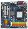
... cards and CPU support lists on ASRock website without notice. More detailed information of this manual occur, the updated version will be available on ASRock website as well. ASRock website http://www.asrock.com 1.1 Package Contents 1 x ASRock ALiveNF4G-DVI Motherboard (Micro ATX Form Factor: 9.6-in x 9.6-in, 24.4 cm x 24.4 cm) 1 x ASRock ALiveNF4G-DVI Quick Installation Guide 1 x ASRock ALiveNF4G-DVI Support CD 1 x Ultra ATA 66...
... cards and CPU support lists on ASRock website without notice. More detailed information of this manual occur, the updated version will be available on ASRock website as well. ASRock website http://www.asrock.com 1.1 Package Contents 1 x ASRock ALiveNF4G-DVI Motherboard (Micro ATX Form Factor: 9.6-in x 9.6-in, 24.4 cm x 24.4 cm) 1 x ASRock ALiveNF4G-DVI Quick Installation Guide 1 x ASRock ALiveNF4G-DVI Support CD 1 x Ultra ATA 66...
Quick Installation Guide
Page 7
... page 46 of the system or damage the CPU. 5. Frequencies other than the recommended CPU bus frequencies may cause the instability of "User Manual" in the future. Although this motherboard offers stepless control, it back again. Microsoft® Windows® VistaTM driver is not recommended to ...enable AMD's Cool 'n' QuietTM technology under Microsoft® Windows® VistaTM / XP 64-bit / XP SP1 or SP2 / 2000 SP4. 9. ASRock website http://www.asrock.com 7 ASRock ALiveNF4G-DVI Motherboard English For audio output, this motherboard supports both stereo and mono modes.
... page 46 of the system or damage the CPU. 5. Frequencies other than the recommended CPU bus frequencies may cause the instability of "User Manual" in the future. Although this motherboard offers stepless control, it back again. Microsoft® Windows® VistaTM driver is not recommended to ...enable AMD's Cool 'n' QuietTM technology under Microsoft® Windows® VistaTM / XP 64-bit / XP SP1 or SP2 / 2000 SP4. 9. ASRock website http://www.asrock.com 7 ASRock ALiveNF4G-DVI Motherboard English For audio output, this motherboard supports both stereo and mono modes.

Quick Installation Guide
Page 9
... socket such that comes with a small triangle. Step 4. English 9 ASRock ALiveNF4G-DVI Motherboard Whenever you handle components. 3. Doing so may cause severe damage to a 90° angle. Install CPU fan and heatsink. Step 2. 2. To avoid damaging the motherboard components due to the instruction manuals of the following precautions before you uninstall any component. Unlock...
... socket such that comes with a small triangle. Step 4. English 9 ASRock ALiveNF4G-DVI Motherboard Whenever you handle components. 3. Doing so may cause severe damage to a 90° angle. Install CPU fan and heatsink. Step 2. 2. To avoid damaging the motherboard components due to the instruction manuals of the following precautions before you uninstall any component. Unlock...

Quick Installation Guide
Page 17
1. Please follow the instruction in our manual and chassis manual to this header. B. E. Enter Advanced Settings, and then select Chipset Configuration. Chassis Speaker Header (4-pin SPEAKER 1) (see p.2 No. 18) Please connect the... Fan Connector (4-pin CPU_FAN1) (see p.2 No. 13) Please connect the chassis speaker to install your system. 2. Pin 1-3 Connected 3-Pin Fan Installation 17 ASRock ALiveNF4G-DVI Motherboard English Click the icon on the chassis must support HDA to connect them for HD audio panel only. Click "Audio I/O", select "Connector Settings" , choose...
1. Please follow the instruction in our manual and chassis manual to this header. B. E. Enter Advanced Settings, and then select Chipset Configuration. Chassis Speaker Header (4-pin SPEAKER 1) (see p.2 No. 18) Please connect the... Fan Connector (4-pin CPU_FAN1) (see p.2 No. 13) Please connect the chassis speaker to install your system. 2. Pin 1-3 Connected 3-Pin Fan Installation 17 ASRock ALiveNF4G-DVI Motherboard English Click the icon on the chassis must support HDA to connect them for HD audio panel only. Click "Audio I/O", select "Connector Settings" , choose...

Quick Installation Guide
Page 20
...shows the wrong example of connecting HDMI_SPDIF cable to the fan connector of PCI Express VGA card. Please refer to your system. 20 ASRock ALiveNF4G-DVI Motherboard Otherwise, the motherboard and the VGA card may cause permanent damage to this motherboard, please carefully follow the below steps. •... to the HDMI_SPDIF connector of HDTV and HDMI VGA card vendor for connector usage in advance. Please refer to the user manual of the HDMI VGA card you install. This motherboard is an all-digital audio/video specification, which provides SPDIF audio output...
...shows the wrong example of connecting HDMI_SPDIF cable to the fan connector of PCI Express VGA card. Please refer to your system. 20 ASRock ALiveNF4G-DVI Motherboard Otherwise, the motherboard and the VGA card may cause permanent damage to this motherboard, please carefully follow the below steps. •... to the HDMI_SPDIF connector of HDTV and HDMI VGA card vendor for connector usage in advance. Please refer to the user manual of the HDMI VGA card you install. This motherboard is an all-digital audio/video specification, which provides SPDIF audio output...
Quick Installation Guide
Page 24
..., "Guide to nVidia RAID Utility for Windows", which is located in the folder at the following path: .. \Information\Manual\RAID Utility for Windows Guide 2.14 Untied Overclocking Technology This motherboard supports Untied Overclocking Technology, which is untied during overclocking,...Support CD for Windows Guide" in the folder at the following path: .. \Information\Manual\RAID Installation Guide After step1, 2, 3, you can operate under a more stable overclocking environment. 24 ASRock ALiveNF4G-DVI Motherboard English Before you start to install Windows® 2000 / Windows® XP...
..., "Guide to nVidia RAID Utility for Windows", which is located in the folder at the following path: .. \Information\Manual\RAID Utility for Windows Guide 2.14 Untied Overclocking Technology This motherboard supports Untied Overclocking Technology, which is untied during overclocking,...Support CD for Windows Guide" in the folder at the following path: .. \Information\Manual\RAID Installation Guide After step1, 2, 3, you can operate under a more stable overclocking environment. 24 ASRock ALiveNF4G-DVI Motherboard English Before you start to install Windows® 2000 / Windows® XP...
Quick Installation Guide
Page 25
... its various sub-menus and to enter BIOS Setup utility; It is designed to display the menus. 25 ASRock ALiveNF4G-DVI Motherboard English For the detailed information about BIOS Setup, please refer to the User Manual (PDF file) contained in the Support CD to be user-friendly. BIOS Information The Flash Memory on the...
... its various sub-menus and to enter BIOS Setup utility; It is designed to display the menus. 25 ASRock ALiveNF4G-DVI Motherboard English For the detailed information about BIOS Setup, please refer to the User Manual (PDF file) contained in the Support CD to be user-friendly. BIOS Information The Flash Memory on the...

Quick Installation Guide
Page 45
.. \ Information\Manual\RAID Installation Guide ® ® ® ® ® ® ® ® ® ..\Information\Manual\RAID Utility for Windows Guide 45 ASRock ALiveNF4G-DVI Motherboard
.. \ Information\Manual\RAID Installation Guide ® ® ® ® ® ® ® ® ® ..\Information\Manual\RAID Utility for Windows Guide 45 ASRock ALiveNF4G-DVI Motherboard
