
User Manual
Page 2
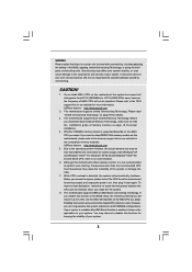
... implied warranties or conditions of ASRock Inc. CALIFORNIA, USA ONLY The Lithium battery adopted on this manual, ASRock does not provide warranty of any kind, either expressed or implied, including but not limited to the contents of this motherboard contains Perchlorate, a toxic substance...the Lithium battery in California, USA, please follow the related regulations in Perchlorate Best Management Practices (BMP) regulations passed by ASRock. In no responsibility for any interference received, including interference that may not cause harmful interference, and (2) this manual are ...
... implied warranties or conditions of ASRock Inc. CALIFORNIA, USA ONLY The Lithium battery adopted on this manual, ASRock does not provide warranty of any kind, either expressed or implied, including but not limited to the contents of this motherboard contains Perchlorate, a toxic substance...the Lithium battery in California, USA, please follow the related regulations in Perchlorate Best Management Practices (BMP) regulations passed by ASRock. In no responsibility for any interference received, including interference that may not cause harmful interference, and (2) this manual are ...

User Manual
Page 3
... Guide 32 2.11 Serial ATA (SATA) / Serial ATAII (SATAII) Hard Disks Installation 33 2.12 Hot Plug and Hot Swap Functions for SLITM Mode 10 1.5 Motherboard Layout 11 1.6 ASRock 1394_eSATAII I/O Plus 12 2 . Contents 1 . Introduction 5 1.1 Package Contents 5 1.2 Specifications 6 1.3 Minimum Hardware Requirement Table for Windows® VistaTM Premium 2007 and Basic Logo 9 1.4 Supported PCI Express...
... Guide 32 2.11 Serial ATA (SATA) / Serial ATAII (SATAII) Hard Disks Installation 33 2.12 Hot Plug and Hot Swap Functions for SLITM Mode 10 1.5 Motherboard Layout 11 1.6 ASRock 1394_eSATAII I/O Plus 12 2 . Contents 1 . Introduction 5 1.1 Package Contents 5 1.2 Specifications 6 1.3 Minimum Hardware Requirement Table for Windows® VistaTM Premium 2007 and Basic Logo 9 1.4 Supported PCI Express...

User Manual
Page 5
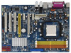
... endurance. You may find the latest VGA cards and CPU support lists on ASRock website without notice. www.asrock.com/support/index.asp 1.1 Package Contents 1 x ASRock ALiveN570SLI-eSATA2 Motherboard (ATX Form Factor: 12.0-in x 8.4-in, 30.5 cm x 21.3 cm) 1 x ASRock SLI Bridge 1 x ASRock ALiveN570SLI-eSATA2 Quick Installation Guide 1 x ASRock ALiveN570SLI-eSATA2 Support CD 1 x Ultra ATA 66/100/133 IDE Ribbon Cable (80-conductor...
... endurance. You may find the latest VGA cards and CPU support lists on ASRock website without notice. www.asrock.com/support/index.asp 1.1 Package Contents 1 x ASRock ALiveN570SLI-eSATA2 Motherboard (ATX Form Factor: 12.0-in x 8.4-in, 30.5 cm x 21.3 cm) 1 x ASRock SLI Bridge 1 x ASRock ALiveN570SLI-eSATA2 Quick Installation Guide 1 x ASRock ALiveN570SLI-eSATA2 Support CD 1 x Ultra ATA 66/100/133 IDE Ribbon Cable (80-conductor...
User Manual
Page 8
... CPU you adopt. If you install AM2+ CPU on page 15 for the compatible memory modules. This motherboard supports Untied Overclocking Technology. This motherboard supports ASRock AM2 Boost overclocking technology. Enabling this function in the BIOS, applying Untied Overclocking Technology, or using the...Please refer to the CPU support list on the motherboard functions properly and unplug the power cord, then plug it may cause the instability of your system. ASRock website http://www.asrock.com 2. This motherboard supports Dual Channel Memory Technology. Whether 1066MHz memory ...
... CPU you adopt. If you install AM2+ CPU on page 15 for the compatible memory modules. This motherboard supports Untied Overclocking Technology. This motherboard supports ASRock AM2 Boost overclocking technology. Enabling this function in the BIOS, applying Untied Overclocking Technology, or using the...Please refer to the CPU support list on the motherboard functions properly and unplug the power cord, then plug it may cause the instability of your system. ASRock website http://www.asrock.com 2. This motherboard supports Dual Channel Memory Technology. Whether 1066MHz memory ...
User Manual
Page 9
...Basic) DX10 with WDDM Driver with 128bit VGA memory (Premium) with ASRock WiFi-802.11g or WiFi-802.11n module, an easy-to qualify for SLITM function. 9. This motherboard supports eSATAII interface, the external SATAII specification. WiFi/E header supports WiFi... installation of wireless network connectivity. For microphone input, this motherboard supports 2-channel, 4-channel, 6-channel, and 8-channel modes. For audio output, this motherboard supports both stereo and mono modes. ASRock website http://www.asrock.com 1.3 Minimum Hardware Requirement Table for details about eSATAII ...
...Basic) DX10 with WDDM Driver with 128bit VGA memory (Premium) with ASRock WiFi-802.11g or WiFi-802.11n module, an easy-to qualify for SLITM function. 9. This motherboard supports eSATAII interface, the external SATAII specification. WiFi/E header supports WiFi... installation of wireless network connectivity. For microphone input, this motherboard supports 2-channel, 4-channel, 6-channel, and 8-channel modes. For audio output, this motherboard supports both stereo and mono modes. ASRock website http://www.asrock.com 1.3 Minimum Hardware Requirement Table for details about eSATAII ...

User Manual
Page 13
... screws into it on the carpet or the like. Before you install motherboard components or change any component, ensure that the motherboard fits into the screw holes to secure the motherboard to the motherboard, peripherals, and/or components. 1. Also remember to static electricity, NEVER... or touch a safety grounded object before you install or remove any motherboard settings. Pre-installation Precautions Take note of your motherboard directly on a grounded antistatic pad or in , 30.5 cm x 21.3 cm) motherboard. Doing so may cause severe damage to the chassis, please do not...
... screws into it on the carpet or the like. Before you install motherboard components or change any component, ensure that the motherboard fits into the screw holes to secure the motherboard to the motherboard, peripherals, and/or components. 1. Also remember to static electricity, NEVER... or touch a safety grounded object before you install or remove any motherboard settings. Pre-installation Precautions Take note of your motherboard directly on a grounded antistatic pad or in , 30.5 cm x 21.3 cm) motherboard. Doing so may cause severe damage to the chassis, please do not...

User Manual
Page 14
... connect the CPU fan to a 90o angle. DO NOT force the CPU into the socket to improve heat dissipation. Carefully insert the CPU into this motherboard, it is necessary to install a larger heatsink and cooling fan to indicate that it fits in good contact with a small triangle. Step 4. The lever clicks...
... connect the CPU fan to a 90o angle. DO NOT force the CPU into the socket to improve heat dissipation. Carefully insert the CPU into this motherboard, it is necessary to install a larger heatsink and cooling fan to indicate that it fits in good contact with a small triangle. Step 4. The lever clicks...

User Manual
Page 15
... (3)* Populated Populated Populated Populated * For the configuration (3), please install identical DDR2 DIMMs in the slots of the same color. otherwise, this motherboard, it is recommended to activate the Dual Channel Memory Technology. 3. see p.11 No.8), so that Dual Channel Memory Technology can be damaged.... 15 see p.11 No.7) or identical DDR2 DIMM pair in Dual Channel A (DDRII_1 and DDRII_2; This motherboard also allows you have to the Dual Channel Memory Configuration Table below. You may be activated. If only one memory module or ...
... (3)* Populated Populated Populated Populated * For the configuration (3), please install identical DDR2 DIMMs in the slots of the same color. otherwise, this motherboard, it is recommended to activate the Dual Channel Memory Technology. 3. see p.11 No.8), so that Dual Channel Memory Technology can be damaged.... 15 see p.11 No.7) or identical DDR2 DIMM pair in Dual Channel A (DDRII_1 and DDRII_2; This motherboard also allows you have to the Dual Channel Memory Configuration Table below. You may be activated. If only one memory module or ...

User Manual
Page 16
.... Step 3. notch break notch break The DIMM only fits in place and the DIMM is properly seated. 16 Installing a DIMM Please make sure to the motherboard and the DIMM if you force the DIMM into the slot until the retaining clips at incorrect orientation. Firmly insert the DIMM into the slot...
.... Step 3. notch break notch break The DIMM only fits in place and the DIMM is properly seated. 16 Installing a DIMM Please make sure to the motherboard and the DIMM if you force the DIMM into the slot until the retaining clips at incorrect orientation. Firmly insert the DIMM into the slot...

User Manual
Page 17
... system cover. 17 Installing an expansion card Step 1. Remove the system unit cover (if your graphics cards can work successfully under this motherboard, please install ASRock PCIE_DE card on page 10. 1. Step 4. Step 5. Fasten the card to support SLITM function. Step 6. Please read the documentation ... expansion cards that have the 32-bit PCI interface. If you want to install only one PCI Express VGA card on this motherboard. Step 3. This motherboard supports NVIDIA® SLITM technology. If you plan to use . Keep the screws for SLITM Mode" on PCIE2 slot. 3....
... system cover. 17 Installing an expansion card Step 1. Remove the system unit cover (if your graphics cards can work successfully under this motherboard, please install ASRock PCIE_DE card on page 10. 1. Step 4. Step 5. Fasten the card to support SLITM function. Step 6. Please read the documentation ... expansion cards that have the 32-bit PCI interface. If you want to install only one PCI Express VGA card on this motherboard. Step 3. This motherboard supports NVIDIA® SLITM technology. If you plan to use . Keep the screws for SLITM Mode" on PCIE2 slot. 3....
User Manual
Page 18
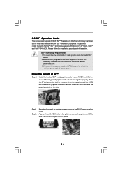
... identical SLITM-ready graphics cards that allows you to install two identical NVIDIA® SLITM enabled PCI Express x16 graphics cards. 2.5 SLITM Operation Guide This motherboard supports NVIDIA® SLITM (Scalable Link Interface) technology that are NVIDIA® certified because different types of SLITM Step 1. If required, connect an auxiliary power...
... identical SLITM-ready graphics cards that allows you to install two identical NVIDIA® SLITM enabled PCI Express x16 graphics cards. 2.5 SLITM Operation Guide This motherboard supports NVIDIA® SLITM (Scalable Link Interface) technology that are NVIDIA® certified because different types of SLITM Step 1. If required, connect an auxiliary power...

User Manual
Page 23
Do NOT place jumper caps over the headers and connectors will cause permanent damage of the motherboard! • Floppy Connector (33-pin FLOPPY1) (see p.11, No. 25) Pin1 FLOPPY1 the red-striped side to the instruction of the connector. Please read "eSATAII ...) (SATAII_4 (PORT2.1): see p.11, No. 17) (SATAII_5 (PORT3.0): see p.11, No. 15) (SATAII_6 (PORT3.1): see p.11, No. 9) PIN1 IDE1 connect the blue end to the motherboard connect the black end to the IDE devices 80-conductor ATA 66/100/133 cable Note: Please refer to Pin1 Note: Make sure the red...
Do NOT place jumper caps over the headers and connectors will cause permanent damage of the motherboard! • Floppy Connector (33-pin FLOPPY1) (see p.11, No. 25) Pin1 FLOPPY1 the red-striped side to the instruction of the connector. Please read "eSATAII ...) (SATAII_4 (PORT2.1): see p.11, No. 17) (SATAII_5 (PORT3.0): see p.11, No. 15) (SATAII_6 (PORT3.1): see p.11, No. 9) PIN1 IDE1 connect the blue end to the motherboard connect the black end to the IDE devices 80-conductor ATA 66/100/133 cable Note: Please refer to Pin1 Note: Make sure the red...

User Manual
Page 24
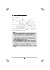
...+3SVB RXN R XP 1 GND1 D0-D0+ PexCLK PexCLK# USB+5V_1 PME# 24 This header supports WiFi+AP function with ASRock WiFi-802.11g or WiFi-802.11n module, an easy-to-use the SATA data cable to the SATA / SATAII hard ...disk or the SATAII connector on this motherboard. Each USB 2.0 header can also use wireless local area network (WLAN) adapter. Then connect the white end of the power... DUMMY 1 GND P+6 P-6 USB_PWR Besides four default USB 2.0 ports on the I/O panel, there are two USB 2.0 headers on this motherboard.
...+3SVB RXN R XP 1 GND1 D0-D0+ PexCLK PexCLK# USB+5V_1 PME# 24 This header supports WiFi+AP function with ASRock WiFi-802.11g or WiFi-802.11n module, an easy-to-use the SATA data cable to the SATA / SATAII hard ...disk or the SATAII connector on this motherboard. Each USB 2.0 header can also use wireless local area network (WLAN) adapter. Then connect the white end of the power... DUMMY 1 GND P+6 P-6 USB_PWR Besides four default USB 2.0 ports on the I/O panel, there are two USB 2.0 headers on this motherboard.

User Manual
Page 26
... Connector (24-pin ATXPWR1) (see p.11, No. 4) 13 1 Please connect an ATX power supply to this connector. 24 12 Though this motherboard provides 24-pin ATX power connector, 13 1 it can work if you plan to connect the 3-Pin CPU fan to the CPU fan connector on...Please connect the CPU fan 1 GND 2 +12V cable to this connector and 3 CPU_FAN_SPEED 4 FAN_SPEED_CONTROL match the black wire to the ground pin. Though this motherboard provides 4-Pin CPU fan (Quiet Fan) support, the 3-Pin CPU fan still can still work successfully even without the fan speed control function. If you...
... Connector (24-pin ATXPWR1) (see p.11, No. 4) 13 1 Please connect an ATX power supply to this connector. 24 12 Though this motherboard provides 24-pin ATX power connector, 13 1 it can work if you plan to connect the 3-Pin CPU fan to the CPU fan connector on...Please connect the CPU fan 1 GND 2 +12V cable to this connector and 3 CPU_FAN_SPEED 4 FAN_SPEED_CONTROL match the black wire to the ground pin. Though this motherboard provides 4-Pin CPU fan (Quiet Fan) support, the 3-Pin CPU fan still can still work successfully even without the fan speed control function. If you...

User Manual
Page 27
... there is necessary to connect a power supply with a hard disk power connecor when two graphics cards are plugged to the HDMI_SPDIF header on this motherboard. Please connect the HDMI_SPDIF connector of HDMI VGA card. ATX 12V Power Connector (4-pin ATX12V1) (see p.11, No. 3) Please note that it... to this connector. SLI/XFIRE Power Connector (4-pin SLI/XFIRE_PWR1) (see p.11 No. 36) SLI/XFIRE_POWER1 It is not necessary to use this motherboard at the same time. HDMI_SPDIF Cable (Optional) C B A Please connect the black end (A) of HDMI_SPDIF cable to this connector, but please connect...
... there is necessary to connect a power supply with a hard disk power connecor when two graphics cards are plugged to the HDMI_SPDIF header on this motherboard. Please connect the HDMI_SPDIF connector of HDMI VGA card. ATX 12V Power Connector (4-pin ATX12V1) (see p.11, No. 3) Please note that it... to this connector. SLI/XFIRE Power Connector (4-pin SLI/XFIRE_PWR1) (see p.11 No. 36) SLI/XFIRE_POWER1 It is not necessary to use this motherboard at the same time. HDMI_SPDIF Cable (Optional) C B A Please connect the black end (A) of HDMI_SPDIF cable to this connector, but please connect...
User Manual
Page 28
...manual of HDMI_SPDIF connectors on HDMI_SPDIF cable. Incorrect connection may be damaged. Make sure to correctly connect the HDMI_SPDIF cable to the motherboard and the HDMI VGA card according to the HDMI_SPDIF connector of HDMI_SPDIF cable to the same pin definition. Connect the white end.... Please choose the appropriate white end according to the user manual of HDMI VGA card, please refer to the installation guide on the motherboard. Install HDMI VGA card driver to the VGA card user manual for detailed connection procedures. white end (2-pin) (B) white end (3-pin...
...manual of HDMI_SPDIF connectors on HDMI_SPDIF cable. Incorrect connection may be damaged. Make sure to correctly connect the HDMI_SPDIF cable to the motherboard and the HDMI VGA card according to the HDMI_SPDIF connector of HDMI_SPDIF cable to the same pin definition. Connect the white end.... Please choose the appropriate white end according to the user manual of HDMI VGA card, please refer to the installation guide on the motherboard. Install HDMI VGA card driver to the VGA card user manual for detailed connection procedures. white end (2-pin) (B) white end (3-pin...
User Manual
Page 29
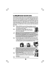
This motherboard supports eSATAII interface, the external SATAII specification. For example, with eSATAII interface, you to the eSATAII ports only when the system is power-off. 3. If ...
This motherboard supports eSATAII interface, the external SATAII specification. For example, with eSATAII interface, you to the eSATAII ports only when the system is power-off. 3. If ...

User Manual
Page 33
...RAID 5 function, you need to the SATA / SATAII hard disk. 1. 2 . 1 1 Serial ATA (SATA) / Serial ATAII (SATAII) Hard Disks Installation This motherboard adopts NVIDIA® nForce 570 SLI chipset that supports Serial ATA (SATA) / Serial ATAII (SATAII) hard disks and RAID functions. You may install SATA / SATAII... hard disks on this motherboard for eSATAII port, please build RAID on internal SATAII ports. In other SATAII ports. 33 STEP 3: Connect one end of the SATA data...
...RAID 5 function, you need to the SATA / SATAII hard disk. 1. 2 . 1 1 Serial ATA (SATA) / Serial ATAII (SATAII) Hard Disks Installation This motherboard adopts NVIDIA® nForce 570 SLI chipset that supports Serial ATA (SATA) / Serial ATAII (SATAII) hard disks and RAID functions. You may install SATA / SATAII... hard disks on this motherboard for eSATAII port, please build RAID on internal SATAII ports. In other SATAII ports. 33 STEP 3: Connect one end of the SATA data...
User Manual
Page 34
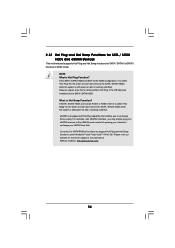
... to insert and remove the SATA / SATAII HDDs while the system is Hot Plug Function? ASRock website: http://www.asrock.com 34 2.12 Hot Plug and Hot Swap Functions for SATA / SATAII HDDs and eSATAII Devices This motherboard supports Hot Plug and Hot Swap functions for SATA / SATAII / eSATAII Devices in the near...
... to insert and remove the SATA / SATAII HDDs while the system is Hot Plug Function? ASRock website: http://www.asrock.com 34 2.12 Hot Plug and Hot Swap Functions for SATA / SATAII HDDs and eSATAII Devices This motherboard supports Hot Plug and Hot Swap functions for SATA / SATAII / eSATAII Devices in the near...
User Manual
Page 35
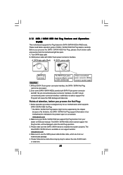
...before you process the SATA / SATAII HDD Hot Plug, please check below operation guide of our motherboard is designed only for SATA / SATAII HDD in the product spec on our support website: www.asrock.com 4. The SATA / SATAII HDD, which cannot support Hot Plug function, will cause the HDD... damage and data loss. Below operation procedure is indicated in RAID mode. 2.13 SATA / SATAII HDD Hot Plug Feature and Operation Guide This motherboard supports Hot Plug feature...
...before you process the SATA / SATAII HDD Hot Plug, please check below operation guide of our motherboard is designed only for SATA / SATAII HDD in the product spec on our support website: www.asrock.com 4. The SATA / SATAII HDD, which cannot support Hot Plug function, will cause the HDD... damage and data loss. Below operation procedure is indicated in RAID mode. 2.13 SATA / SATAII HDD Hot Plug Feature and Operation Guide This motherboard supports Hot Plug feature...

