
User Manual
Page 1
All rights reserved. 1 ALiveN570SLI-eSATA2 User Manual Version 1.0 Published January 2008 Copyright©2008 ASRock INC.
All rights reserved. 1 ALiveN570SLI-eSATA2 User Manual Version 1.0 Published January 2008 Copyright©2008 ASRock INC.

User Manual
Page 2
...subject to the implied warranties or conditions of merchantability or fitness for a particular purpose. With respect to the contents of this manual, ASRock does not provide warranty of any kind, either expressed or implied, including but not limited to the following two conditions: ...may appear in advance. When you discard the Lithium battery in California, USA, please follow the related regulations in this manual. ASRock assumes no event shall ASRock, its directors, officers, employees, or agents be reproduced, transcribed, transmitted, or translated in any language, in any ...
...subject to the implied warranties or conditions of merchantability or fitness for a particular purpose. With respect to the contents of this manual, ASRock does not provide warranty of any kind, either expressed or implied, including but not limited to the following two conditions: ...may appear in advance. When you discard the Lithium battery in California, USA, please follow the related regulations in this manual. ASRock assumes no event shall ASRock, its directors, officers, employees, or agents be reproduced, transcribed, transmitted, or translated in any language, in any ...

User Manual
Page 5
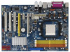
... the BIOS software might be updated, the content of this manual will be subject to the hardware installation. www.asrock.com/support/index.asp 1.1 Package Contents 1 x ASRock ALiveN570SLI-eSATA2 Motherboard (ATX Form Factor: 12.0-in x 8.4-in, 30.5 cm x 21.3 cm) 1 x ASRock SLI Bridge 1 x ASRock ALiveN570SLI-eSATA2 Quick Installation Guide 1 x ASRock ALiveN570SLI-eSATA2 Support CD 1 x Ultra ATA 66/100/133 IDE Ribbon Cable...
... the BIOS software might be updated, the content of this manual will be subject to the hardware installation. www.asrock.com/support/index.asp 1.1 Package Contents 1 x ASRock ALiveN570SLI-eSATA2 Motherboard (ATX Form Factor: 12.0-in x 8.4-in, 30.5 cm x 21.3 cm) 1 x ASRock SLI Bridge 1 x ASRock ALiveN570SLI-eSATA2 Quick Installation Guide 1 x ASRock ALiveN570SLI-eSATA2 Support CD 1 x Ultra ATA 66/100/133 IDE Ribbon Cable...

User Manual
Page 14
... triangle. Carefully insert the CPU into this motherboard, it fits in one correct orientation. Step 4. The lever clicks on the side tab to the instruction manuals of the pins. Then connect the CPU fan to avoid bending of the CPU fan and the heatsink. 14 2.1 CPU Installation Step 1. Position the CPU...
... triangle. Carefully insert the CPU into this motherboard, it fits in one correct orientation. Step 4. The lever clicks on the side tab to the instruction manuals of the pins. Then connect the CPU fan to avoid bending of the CPU fan and the heatsink. 14 2.1 CPU Installation Step 1. Position the CPU...
User Manual
Page 25
... (9-pin HD_AUDIO1) (see p.11, No. 30) CD1 CD-L GND GND CD-R This header supports the Hot Plug detection function for ASRock DeskExpress. Please follow the instruction in our manual and chassis manual to connect them for HD audio panel only. If you to receive stereo audio input from [Auto] to MIC2_L. Connect Mic_IN...
... (9-pin HD_AUDIO1) (see p.11, No. 30) CD1 CD-L GND GND CD-R This header supports the Hot Plug detection function for ASRock DeskExpress. Please follow the instruction in our manual and chassis manual to connect them for HD audio panel only. If you to receive stereo audio input from [Auto] to MIC2_L. Connect Mic_IN...
User Manual
Page 28
.... Step 2. For the pin definition of HDMI VGA card vendor. Please choose the appropriate white end according to the user manual of HDMI_SPDIF connectors on the motherboard. This motherboard is an all-digital audio/video specification, which provides SPDIF audio output to ...(2-pin) (B) white end (3-pin) (C) Step 4. Please refer to your system. 28 Install HDMI VGA card driver to the VGA card user manual for detailed connection procedures. A complete HDMI system requires a HDMI VGA card and a HDMI ready motherboard with a HDMI_SPDIF header, which provides an interface...
.... Step 2. For the pin definition of HDMI VGA card vendor. Please choose the appropriate white end according to the user manual of HDMI_SPDIF connectors on the motherboard. This motherboard is an all-digital audio/video specification, which provides SPDIF audio output to ...(2-pin) (B) white end (3-pin) (C) Step 4. Please refer to your system. 28 Install HDMI VGA card driver to the VGA card user manual for detailed connection procedures. A complete HDMI system requires a HDMI VGA card and a HDMI ready motherboard with a HDMI_SPDIF header, which provides an interface...
User Manual
Page 35
... interfaces, the IDE 1x4-pin conventional power connector interface is available on our website: www.asrock.com 2. Below operation procedure is installed into system properly. Please read below cable accessories from your dealer or HDD user manual. Please make sure the SATA / SATAII driver is designed only for SATA / SATAII HDD in...
... interfaces, the IDE 1x4-pin conventional power connector interface is available on our website: www.asrock.com 2. Below operation procedure is installed into system properly. Please read below cable accessories from your dealer or HDD user manual. Please make sure the SATA / SATAII driver is designed only for SATA / SATAII HDD in...
User Manual
Page 42
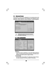
3.3 Advanced Screen In this section, you will enable ASRock AM2 Boost function, which will be left at the rated frequency/voltage. Setting wrong values in this section may cause the system to malfunction. ... items: CPU Configuration, Chipset Configuration, ACPI Configuration, IDE Configuration, PCIPnP Configuration, Floppy Configuration, SuperIO Configuration, and USB Configuration. The default value is [Disabled]. If Manual, multiplier and voltage will improve the memory performance. Please refer to caution 8 on User Selection in below sections may set this to Sub Screen F1...
3.3 Advanced Screen In this section, you will enable ASRock AM2 Boost function, which will be left at the rated frequency/voltage. Setting wrong values in this section may cause the system to malfunction. ... items: CPU Configuration, Chipset Configuration, ACPI Configuration, IDE Configuration, PCIPnP Configuration, Floppy Configuration, SuperIO Configuration, and USB Configuration. The default value is [Disabled]. If Manual, multiplier and voltage will improve the memory performance. Please refer to caution 8 on User Selection in below sections may set this to Sub Screen F1...

User Manual
Page 43
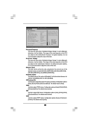
...]. If you may reduce CPU voltage and memory frequency, and lead to [Disable] if above issue occurs. Multiplier/Voltage Change This item is set to [Manual], you install Windows® VistaTM and want to enable this function, please set to [Enabled] as default. Cool 'n' Quiet Use this option is recommended to...
...]. If you may reduce CPU voltage and memory frequency, and lead to [Disable] if above issue occurs. Multiplier/Voltage Change This item is set to [Manual], you install Windows® VistaTM and want to enable this function, please set to [Enabled] as default. Cool 'n' Quiet Use this option is recommended to...
User Manual
Page 44
... Voltage Memory Clock [Disabled] [Auto] [200] [100] [Center Spread] [Enabled] [Enabled] [Enabled] [Auto] [Enabled] x9.0 1800 MHz 1.400 V [Manual] [x9.0 1800 MHz] [1.350 V] [Auto] If AUTO, multiplier and voltage will be set based on User Selection in Setup. +F1 F9 F10 ESC Select Screen...left at the rated frequency/voltage. Configuration options: [Auto], [3CLK], [4CLK], [5CLK] and [6CLK]. The default value is [Auto]. If Manual, multiplier and voltage will show when "Multiplier/Voltage Change" is [Disabled]. TRCD Use this item. TRTP Use this option is set one of ...
... Voltage Memory Clock [Disabled] [Auto] [200] [100] [Center Spread] [Enabled] [Enabled] [Enabled] [Auto] [Enabled] x9.0 1800 MHz 1.400 V [Manual] [x9.0 1800 MHz] [1.350 V] [Auto] If AUTO, multiplier and voltage will be set based on User Selection in Setup. +F1 F9 F10 ESC Select Screen...left at the rated frequency/voltage. Configuration options: [Auto], [3CLK], [4CLK], [5CLK] and [6CLK]. The default value is [Auto]. If Manual, multiplier and voltage will show when "Multiplier/Voltage Change" is [Disabled]. TRCD Use this item. TRTP Use this option is set one of ...

Quick Installation Guide
Page 4
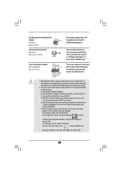
... further notice. More detailed information of this manual occur, the updated version will be found in the user manual presented in Floppy Drive Ribbon Cable 2 x Serial ATA (SATA) Data Cables (Optional) 1 x Serial ATA (SATA) HDD Power Cable (Optional) 1 x HDMI_SPDIF Cable (Optional) 1 x "ASRock 1394_eSATAII I/O Plus" I/O Shield 4 ASRock ALiveN570SLI-eSATA2 Motherboard English In case any modifications of the...
... further notice. More detailed information of this manual occur, the updated version will be found in the user manual presented in Floppy Drive Ribbon Cable 2 x Serial ATA (SATA) Data Cables (Optional) 1 x Serial ATA (SATA) HDD Power Cable (Optional) 1 x HDMI_SPDIF Cable (Optional) 1 x "ASRock 1394_eSATAII I/O Plus" I/O Shield 4 ASRock ALiveN570SLI-eSATA2 Motherboard English In case any modifications of the...

Quick Installation Guide
Page 11
... it fits in one correct orientation. Then connect the CPU fan to avoid bending of the CPU fan and the heatsink. English 11 ASRock ALiveN570SLI-eSATA2 Motherboard Position the CPU directly above the socket such that the CPU and the heatsink are securely fastened and in place, press it firmly... STEP 4: Push Down And Lock The Socket Lever 2.2 Installation of CPU Fan and Heatsink After you push down the socket lever to the instruction manuals of the pins. For proper installation, please kindly refer to secure the CPU. 2.1 CPU Installation Step 1. Make sure that the CPU corner with...
... it fits in one correct orientation. Then connect the CPU fan to avoid bending of the CPU fan and the heatsink. English 11 ASRock ALiveN570SLI-eSATA2 Motherboard Position the CPU directly above the socket such that the CPU and the heatsink are securely fastened and in place, press it firmly... STEP 4: Push Down And Lock The Socket Lever 2.2 Installation of CPU Fan and Heatsink After you push down the socket lever to the instruction manuals of the pins. For proper installation, please kindly refer to secure the CPU. 2.1 CPU Installation Step 1. Make sure that the CPU corner with...

Quick Installation Guide
Page 22
... allows you use AC'97 audio panel, please install it to [Enabled]. Connect Mic_IN (MIC) to function correctly. English 22 ASRock ALiveN570SLI-eSATA2 Motherboard Please follow the instruction in our manual and chassis manual to Ground (GND). Connect Ground (GND) to install your system. 2. D. Enter BIOS Setup Utility. Click the icon on... detection function for the front panel audio cable that allows convenient connection and control of audio devices. 1. This is an interface for ASRock DeskExpress. Connect Audio_R (RIN) to OUT2_R and Audio_L (LIN) to enter Realtek HD Audio Manager.
... allows you use AC'97 audio panel, please install it to [Enabled]. Connect Mic_IN (MIC) to function correctly. English 22 ASRock ALiveN570SLI-eSATA2 Motherboard Please follow the instruction in our manual and chassis manual to Ground (GND). Connect Ground (GND) to install your system. 2. D. Enter BIOS Setup Utility. Click the icon on... detection function for the front panel audio cable that allows convenient connection and control of audio devices. 1. This is an interface for ASRock DeskExpress. Connect Audio_R (RIN) to OUT2_R and Audio_L (LIN) to enter Realtek HD Audio Manager.
Quick Installation Guide
Page 25
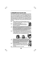
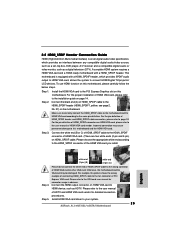
... Please refer to HDMI device, such as a digital television (DTV). To use HDMI function on HDMI VGA card to the user manual of the HDMI VGA card you install. Incorrect connection may be damaged. Please choose the appropriate white end according to this motherboard. ...vendor. Step 2. Make sure to correctly connect the HDMI_SPDIF cable to the motherboard and the HDMI VGA card according to your system. 25 ASRock ALiveN570SLI-eSATA2 Motherboard Please refer to the HDMI_SPDIF header (HDMI_SPDIF1, yellow, see page 2, No. 27) on this motherboard and the HDMI VGA card....
... Please refer to HDMI device, such as a digital television (DTV). To use HDMI function on HDMI VGA card to the user manual of the HDMI VGA card you install. Incorrect connection may be damaged. Please choose the appropriate white end according to this motherboard. ...vendor. Step 2. Make sure to correctly connect the HDMI_SPDIF cable to the motherboard and the HDMI VGA card according to your system. 25 ASRock ALiveN570SLI-eSATA2 Motherboard Please refer to the HDMI_SPDIF header (HDMI_SPDIF1, yellow, see page 2, No. 27) on this motherboard and the HDMI VGA card....

Quick Installation Guide
Page 30
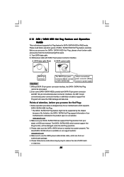
... "User Manual" in the Support CD. For example, with Hot Plug capability that it is still power-on and in working condition. Currently, the SATA RAID driver does not support Hot Plug and Hot Swap functions under Windows® VistaTM and VistaTM 64-bit OS. ASRock website: http://www.asrock.com 30 ASRock ALiveN570SLI-eSATA2 Motherboard...
... "User Manual" in the Support CD. For example, with Hot Plug capability that it is still power-on and in working condition. Currently, the SATA RAID driver does not support Hot Plug and Hot Swap functions under Windows® VistaTM and VistaTM 64-bit OS. ASRock website: http://www.asrock.com 30 ASRock ALiveN570SLI-eSATA2 Motherboard...

Quick Installation Guide
Page 34
...-bit / VistaTM / VistaTM 64-bit. 3. If you start up the computer, please press during the Power-On-Self-Test (POST) to display the menus. 34 ASRock ALiveN570SLI-eSATA2 Motherboard English BIOS Information The Flash Memory on the file "ASSETUP.EXE" from the "BIN" folder in the Support CD to enter BIOS Setup utility... features. The Support CD that will display the Main Menu automatically if "AUTORUN" is enabled in the Support CD. 4. When you wish to the User Manual (PDF file) contained in your CDROM drive.
...-bit / VistaTM / VistaTM 64-bit. 3. If you start up the computer, please press during the Power-On-Self-Test (POST) to display the menus. 34 ASRock ALiveN570SLI-eSATA2 Motherboard English BIOS Information The Flash Memory on the file "ASSETUP.EXE" from the "BIN" folder in the Support CD to enter BIOS Setup utility... features. The Support CD that will display the Main Menu automatically if "AUTORUN" is enabled in the Support CD. 4. When you wish to the User Manual (PDF file) contained in your CDROM drive.

RAID Installation Guide
Page 2
... identical drives of the same model and capacity when creating a RAID set the option to RAID mode by following the detailed instruction of the "User Manual" in parallel, interleaved stacks. RAID 1 (Data Mirroring) RAID 1 is called data striping that copies and maintains an identical image of Independent Disks", which is an...
... identical drives of the same model and capacity when creating a RAID set the option to RAID mode by following the detailed instruction of the "User Manual" in parallel, interleaved stacks. RAID 1 (Data Mirroring) RAID 1 is called data striping that copies and maintains an identical image of Independent Disks", which is an...
