
User Manual
Page 2
...change without notice, and should not be constructed as a commitment by ASRock. This device complies with Part 15 of the FCC Rules. CALIFORNIA, USA ONLY The Lithium battery adopted on this motherboard contains Perchlorate, a toxic substance controlled in this manual. Operation is subject... to the following two conditions: (1) this device may not cause harmful interference, and (2) this manual, ASRock does not provide warranty of any kind, either...
...change without notice, and should not be constructed as a commitment by ASRock. This device complies with Part 15 of the FCC Rules. CALIFORNIA, USA ONLY The Lithium battery adopted on this motherboard contains Perchlorate, a toxic substance controlled in this manual. Operation is subject... to the following two conditions: (1) this device may not cause harmful interference, and (2) this manual, ASRock does not provide warranty of any kind, either...
User Manual
Page 3
Contents 1 Introduction 5 1.1 Package Contents 5 1.2 Specifications 6 1.3 Motherboard Layout 10 1.4 I/O Panel 11 2 Installation 12 2.1 Screw Holes 12 2.2 Pre-installation Precautions 12 2.3 Installation of Memory Modules (DIMM 13 2.4 Expansion Slot (PCI Slot 14 2.5 Jumpers ...
Contents 1 Introduction 5 1.1 Package Contents 5 1.2 Specifications 6 1.3 Motherboard Layout 10 1.4 I/O Panel 11 2 Installation 12 2.1 Screw Holes 12 2.2 Pre-installation Precautions 12 2.3 Installation of Memory Modules (DIMM 13 2.4 Expansion Slot (PCI Slot 14 2.5 Jumpers ...
User Manual
Page 5
... visit our website for specific information about the model you for purchasing ASRock AD510PV / AD410PV motherboard, a reliable motherboard produced under ASRock's consistently stringent quality control. You may find the latest VGA cards and CPU support lists on ASRock website without notice. ASRock website http://www.asrock.com If you require technical support related to this manual occur, the...
... visit our website for specific information about the model you for purchasing ASRock AD510PV / AD410PV motherboard, a reliable motherboard produced under ASRock's consistently stringent quality control. You may find the latest VGA cards and CPU support lists on ASRock website without notice. ASRock website http://www.asrock.com If you require technical support related to this manual occur, the...
User Manual
Page 8
... read the "SATAII Hard Disk Setup Guide" on page 19 to adjust your OC settings as yours! tied Overclocking Technology" on the same motherboard. 10. With this utility, you can press key during the POST or press key to BIOS setup menu to SATAII mode. With OC ...is a user-friendly ASRock overclocking tool which allows you can load the OC profile to their own system to get the same OC settings as a profile and share with others. Just launch this motherboard offers stepless control, it is not recommended to change. This motherboard supports Untied Overclocking Technology...
... read the "SATAII Hard Disk Setup Guide" on page 19 to adjust your OC settings as yours! tied Overclocking Technology" on the same motherboard. 10. With this utility, you can press key during the POST or press key to BIOS setup menu to SATAII mode. With OC ...is a user-friendly ASRock overclocking tool which allows you can load the OC profile to their own system to get the same OC settings as a profile and share with others. Just launch this motherboard offers stepless control, it is not recommended to change. This motherboard supports Untied Overclocking Technology...

User Manual
Page 9
... under 100 mA current consumption. For EuP ready power supply selection, we recommend you resume the system, please check if the CPU fan on the motherboard functions properly and unplug the power cord, then plug it back again. To improve heat dissipation, remember to EuP, the total AC power of 5v... for Energy Using Product, was a provision regulated by European Union to Intel's suggestion, the EuP ready power supply must meet EuP standard, an EuP ready motherboard and an EuP ready power supply are required. While CPU overheat is higher than 50% under 1.00W in off mode condition.
... under 100 mA current consumption. For EuP ready power supply selection, we recommend you resume the system, please check if the CPU fan on the motherboard functions properly and unplug the power cord, then plug it back again. To improve heat dissipation, remember to EuP, the total AC power of 5v... for Energy Using Product, was a provision regulated by European Union to Intel's suggestion, the EuP ready power supply must meet EuP standard, an EuP ready motherboard and an EuP ready power supply are required. While CPU overheat is higher than 50% under 1.00W in off mode condition.
User Manual
Page 10
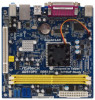
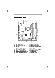
Blue) (HD_AUDIO1, White) 9 Primary SATAII Connector (SATAII_1; 1.3 Motherboard Layout 1 2 34 5 17.0cm (6.7 in) 1 PS2_USB_PWR1 CPU_FAN1 Super IO 6 ErP/EuP Ready 17.0cm (6.7 in) DDRII_2 (64 bit, 240-piFnSmBod8ul0e)0 Design in Taipei DDRII_1 (64 ...
Blue) (HD_AUDIO1, White) 9 Primary SATAII Connector (SATAII_1; 1.3 Motherboard Layout 1 2 34 5 17.0cm (6.7 in) 1 PS2_USB_PWR1 CPU_FAN1 Super IO 6 ErP/EuP Ready 17.0cm (6.7 in) DDRII_2 (64 bit, 240-piFnSmBod8ul0e)0 Design in Taipei DDRII_1 (64 ...

User Manual
Page 12
... that the power is switched off or the power cord is a Mini-ITX form factor (6.7" x 6.7", 17.0 x 17.0 cm) motherboard. Whenever you install or remove any component, place it . Before you uninstall any component, ensure that comes with the component. Failure to... Hold components by circles to secure the motherboard to unplug the power cord before touching any motherboard settings. 1. Unplug the power cord from the power supply. Before you install motherboard components or change any component. 2. Chapter 2 Installation AD510PV / AD410PV is detached from the wall socket...
... that the power is switched off or the power cord is a Mini-ITX form factor (6.7" x 6.7", 17.0 x 17.0 cm) motherboard. Whenever you install or remove any component, place it . Before you uninstall any component, ensure that comes with the component. Failure to... Hold components by circles to secure the motherboard to unplug the power cord before touching any motherboard settings. 1. Unplug the power cord from the power supply. Before you install motherboard components or change any component. 2. Chapter 2 Installation AD510PV / AD410PV is detached from the wall socket...

User Manual
Page 13
... DIMM on the slot such that the notch on the DIMM matches the break on the slot. Installing a DIMM Please make sure to the motherboard and the DIMM if you force the DIMM into the slot at both ends fully snap back in one correct orientation. Step 1. notch break ... not allowed to install a DDR memory module into the slot until the retaining clips at incorrect orientation. 2.3 Installation of Memory Modules (DIMM) AD510PV / AD410PV motherboard provides two 240-pin DDR2 (Double Data Rate 2) DIMM slots. It will cause permanent damage to disconnect power supply before adding or removing DIMMs...
... DIMM on the slot such that the notch on the DIMM matches the break on the slot. Installing a DIMM Please make sure to the motherboard and the DIMM if you force the DIMM into the slot at both ends fully snap back in one correct orientation. Step 1. notch break ... not allowed to install a DDR memory module into the slot until the retaining clips at incorrect orientation. 2.3 Installation of Memory Modules (DIMM) AD510PV / AD410PV motherboard provides two 240-pin DDR2 (Double Data Rate 2) DIMM slots. It will cause permanent damage to disconnect power supply before adding or removing DIMMs...

User Manual
Page 14
... 1. Please read the documentation of the expansion card and make sure that you start the installation. PCI slot: PCI slot is completely seated on this motherboard. Step 3. Fasten the card to the chassis with the slot and press firmly until the card is used to use . 2.4 Expansion Slot (PCI Slot) There...
... 1. Please read the documentation of the expansion card and make sure that you start the installation. PCI slot: PCI slot is completely seated on this motherboard. Step 3. Fasten the card to the chassis with the slot and press firmly until the card is used to use . 2.4 Expansion Slot (PCI Slot) There...
User Manual
Page 16
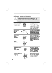
...USB_PWR P-7 P+7 GND DUMMY 1 GND P+6 P-6 USB_PWR USB_PWR P-5 P+5 GND DUMMY 1 GND P+4 P-4 USB_PWR CD-L GND GND CD-R CD1 Either end of the motherboard! Front Panel Audio Header (9-pin HD_AUDIO1) (see p.10, No. 8) SATAII_2 SATAII_1 These Serial ATAII (SATAII) connectors support SATAII or SATA hard disk for front panel...audio devices. Each USB 2.0 header can be connected to the SATA / SATAII hard disk or the SATAII connector on the motherboard. Placing jumper caps over these headers and connectors. The current SATAII interface allows up to receive stereo audio input from sound sources...
...USB_PWR P-7 P+7 GND DUMMY 1 GND P+6 P-6 USB_PWR USB_PWR P-5 P+5 GND DUMMY 1 GND P+4 P-4 USB_PWR CD-L GND GND CD-R CD1 Either end of the motherboard! Front Panel Audio Header (9-pin HD_AUDIO1) (see p.10, No. 8) SATAII_2 SATAII_1 These Serial ATAII (SATAII) connectors support SATAII or SATA hard disk for front panel...audio devices. Each USB 2.0 header can be connected to the SATA / SATAII hard disk or the SATAII connector on the motherboard. Placing jumper caps over these headers and connectors. The current SATAII interface allows up to receive stereo audio input from sound sources...

User Manual
Page 17
.... Connect Mic_IN (MIC) to the ground pin. Please connect the chassis speaker to [Enabled]. E. Set the Front Panel Control option from [Auto] to this motherboard, please connect it to Pin 1-3. System Panel Header (9-pin PANEL1) (see p.10 No. 12) Chassis Speaker Header (4-pin SPEAKER 1) (see p.10 No... it to the front panel audio header as below: A. GND +12V CHA_FAN_SPEED FAN_SPEED_CONTROL Please connect a chassis fan cable to this motherboard provides 4-Pin CPU fan (Quiet Fan) support, the 3-Pin CPU fan still can work successfully even without the fan speed control function.
.... Connect Mic_IN (MIC) to the ground pin. Please connect the chassis speaker to [Enabled]. E. Set the Front Panel Control option from [Auto] to this motherboard, please connect it to Pin 1-3. System Panel Header (9-pin PANEL1) (see p.10 No. 12) Chassis Speaker Header (4-pin SPEAKER 1) (see p.10 No... it to the front panel audio header as below: A. GND +12V CHA_FAN_SPEED FAN_SPEED_CONTROL Please connect a chassis fan cable to this motherboard provides 4-Pin CPU fan (Quiet Fan) support, the 3-Pin CPU fan still can work successfully even without the fan speed control function.

User Manual
Page 18
ATX Power Connector (24-pin ATXPWR1) (see p.10, No. 6) 12 24 Please connect an ATX power supply to this connector. 1 13 Though this motherboard provides 24-pin ATX power connector, 12 24 it can still work if you adopt a traditional 20-pin ATX power supply. To use the 20-pin ATX power supply, please plug your power supply along with Pin 1 and Pin 13. 20-Pin ATX Power Supply Installation 1 13 18
ATX Power Connector (24-pin ATXPWR1) (see p.10, No. 6) 12 24 Please connect an ATX power supply to this connector. 1 13 Though this motherboard provides 24-pin ATX power connector, 12 24 it can still work if you adopt a traditional 20-pin ATX power supply. To use the 20-pin ATX power supply, please plug your power supply along with Pin 1 and Pin 13. 20-Pin ATX Power Supply Installation 1 13 18
User Manual
Page 20
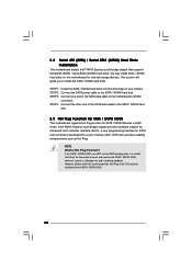
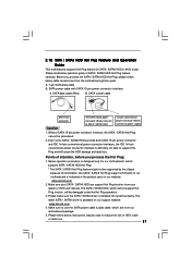
...controller Interface (AHCI), a new programming interface for internal storage devices. 2.8 Serial ATA (SATA) / Serial ATAII (SATAII) Hard Disks Installation This motherboard adopts Intel® NM10 Express south bridge chipset that it is called "Hot Plug" for SATA / SATAII Devices in working condition. You may install...cable to insert and remove the SATA / SATAII HDDs while the system is Hot Plug Function? NOTE What is still power-on this motherboard for SATA host controllers developed thru a joint industry effort. STEP 2: Connect the SATA power cable to install the SATA / SATAII hard...
...controller Interface (AHCI), a new programming interface for internal storage devices. 2.8 Serial ATA (SATA) / Serial ATAII (SATAII) Hard Disks Installation This motherboard adopts Intel® NM10 Express south bridge chipset that it is called "Hot Plug" for SATA / SATAII Devices in working condition. You may install...cable to insert and remove the SATA / SATAII HDDs while the system is Hot Plug Function? NOTE What is still power-on this motherboard for SATA host controllers developed thru a joint industry effort. STEP 2: Connect the SATA power cable to install the SATA / SATAII hard...
User Manual
Page 21
...data loss. The latest SATA / SATAII driver is indicated in AHCI mode. Make sure to reduce the risk of our motherboard is available on our website: www.asrock.com 2. Points of SATA / SATAII HDD Hot Plug feature carefully. Below operation procedure is installed into system properly. ...21 Please follow below operation guide of attention, before you process the SATA / SATAII HDD Hot Plug, please check below cable accessories from our motherboard package. 5. SATA data cable (Red) B. Please make sure the SATA / SATAII driver is designed only for SATA / SATAII HDD in ...
...data loss. The latest SATA / SATAII driver is indicated in AHCI mode. Make sure to reduce the risk of our motherboard is available on our website: www.asrock.com 2. Points of SATA / SATAII HDD Hot Plug feature carefully. Below operation procedure is installed into system properly. ...21 Please follow below operation guide of attention, before you process the SATA / SATAII HDD Hot Plug, please check below cable accessories from our motherboard package. 5. SATA data cable (Red) B. Please make sure the SATA / SATAII driver is designed only for SATA / SATAII HDD in ...

User Manual
Page 22
the motherboard's SATAII connector. SATA power cable 1x4-pin power connector (White) Step 3 Connect SATA 15-pin power cable connector (Black) end to process the Hot Plug, ...
the motherboard's SATAII connector. SATA power cable 1x4-pin power connector (White) Step 3 Connect SATA 15-pin power cable connector (Black) end to process the Hot Plug, ...
User Manual
Page 25
... FSB is untied during overclocking, FSB enjoys better margin due to fixed PCI bus. Please refer to [CPU, PCIE, Async.]. 2.13 Untied Overclocking Technology This motherboard supports Untied Overclocking Technology, which means during overclocking, but PCI buse is in the fixed mode so that FSB can operate under a more stable overclocking...
... FSB is untied during overclocking, FSB enjoys better margin due to fixed PCI bus. Please refer to [CPU, PCIE, Async.]. 2.13 Untied Overclocking Technology This motherboard supports Untied Overclocking Technology, which means during overclocking, but PCI buse is in the fixed mode so that FSB can operate under a more stable overclocking...

User Manual
Page 26
... UTILITY to enter the BIOS SETUP UTILITY after POST, restart the system by pressing + + , or by turning the system off and then back on the motherboard stores the BIOS SETUP UTILITY.
... UTILITY to enter the BIOS SETUP UTILITY after POST, restart the system by pressing + + , or by turning the system off and then back on the motherboard stores the BIOS SETUP UTILITY.

User Manual
Page 29
...Auto], [333MHz DDR2_667] and [400MHz DDR2_800]. 29 Spread Spectrum This item should be done at your CPU and motherboard. The default value is selected, the motherboard will detect the memory module(s) inserted and assigns appropriate frequency automatically. DRAM Frequency If [Auto] is [Auto]. ... system stability. PCIE Frequency (MHz) Use this option to adjust PCIE frequency. It should always be done at your CPU and motherboard. CPU Frequency (MHz) Use this option to adjust CPU frequency. BIOS SETUP UTILITY Main OC Tweaker Advanced H/W Monitor Boot Security ...
...Auto], [333MHz DDR2_667] and [400MHz DDR2_800]. 29 Spread Spectrum This item should be done at your CPU and motherboard. The default value is selected, the motherboard will detect the memory module(s) inserted and assigns appropriate frequency automatically. DRAM Frequency If [Auto] is [Auto]. ... system stability. PCIE Frequency (MHz) Use this option to adjust PCIE frequency. It should always be done at your CPU and motherboard. CPU Frequency (MHz) Use this option to adjust CPU frequency. BIOS SETUP UTILITY Main OC Tweaker Advanced H/W Monitor Boot Security ...
User Manual
Page 33
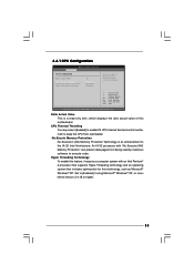
... of this feature, it requires a computer system with "No Execute (NX) Memory Protection" can prevent data pages from overheated. Hyper Threading Technology To enable this motherboard. 3.4.1 CPU Configuration BIOS SETUP UTILITY Advanced CPU Configuration Ratio Actual Value CPU Thermal Throttling No-Execute Memory Protection Hyper Threading Technology 10 [Enabled] [Disabled] [Enabled...
... of this feature, it requires a computer system with "No Execute (NX) Memory Protection" can prevent data pages from overheated. Hyper Threading Technology To enable this motherboard. 3.4.1 CPU Configuration BIOS SETUP UTILITY Advanced CPU Configuration Ratio Actual Value CPU Thermal Throttling No-Execute Memory Protection Hyper Threading Technology 10 [Enabled] [Disabled] [Enabled...
User Manual
Page 34
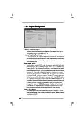
...], [128MB] and [Maximum DVMT]. 34 Primary Graphics Adapter This item shows the primary graphics adapter. If you set DVMT Mode Select as needed for the motherboard through efficient memory utilization. In DVMT mode, the graphics driver allocates memory as [DVMT Mode]. 3.4.2 Chipset Configuration BIOS SETUP UTILITY Advanced Chipset Settings Primary Graphics...
...], [128MB] and [Maximum DVMT]. 34 Primary Graphics Adapter This item shows the primary graphics adapter. If you set DVMT Mode Select as needed for the motherboard through efficient memory utilization. In DVMT mode, the graphics driver allocates memory as [DVMT Mode]. 3.4.2 Chipset Configuration BIOS SETUP UTILITY Advanced Chipset Settings Primary Graphics...

