
User Manual
Page 3
... 2.10 Driver Installation Guide 21 2.11 Installing Windows® 7 / 7 64-bit / VistaTM / VistaTM 64-bit / XP / XP 64-bit Without RAID Functions 21 2.11.1 Installing Windows® XP / XP 64-bit Without RAID Functions 21 2.11.2 Installing Windows® 7 / 7 64-bit / VistaTM / VistaTM 64-bit Without RAID Functions 22 2.12 Untied Overclocking Technology 23 3 BIOS SETUP UTILITY 24 3.1 Introduction 24 3.1.1 BIOS Menu Bar 24 3.1.2 Navigation Keys 25 3.2 Main Screen 25 3.3 OC Tweaker Screen 26 3.4 Advanced Screen 30 3.4.1 CPU Configuration 31 3.4.2 Chipset Configuration 32 3.4.3 ACPI...
... 2.10 Driver Installation Guide 21 2.11 Installing Windows® 7 / 7 64-bit / VistaTM / VistaTM 64-bit / XP / XP 64-bit Without RAID Functions 21 2.11.1 Installing Windows® XP / XP 64-bit Without RAID Functions 21 2.11.2 Installing Windows® 7 / 7 64-bit / VistaTM / VistaTM 64-bit Without RAID Functions 22 2.12 Untied Overclocking Technology 23 3 BIOS SETUP UTILITY 24 3.1 Introduction 24 3.1.1 BIOS Menu Bar 24 3.1.2 Navigation Keys 25 3.2 Main Screen 25 3.3 OC Tweaker Screen 26 3.4 Advanced Screen 30 3.4.1 CPU Configuration 31 3.4.2 Chipset Configuration 32 3.4.3 ACPI...
User Manual
Page 7
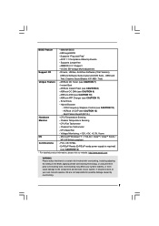
OEM and Trial; Boot Failure Guard (B.F.G.) Hardware - Voltage Monitoring: +12V, +5V, +3.3V, Vcore OS - ErP/EuP Ready (ErP/EuP ready power supply is a certain risk involved with overclocking, including adjusting the setting in the BIOS, applying Untied Overclocking Technology, or using the thirdparty overclocking tools. Supports jumperfree - Drivers, Utilities, AntiVirus Software (Trial Version), ASRock Software Suite (CyberLink DVD Suite - Creative Sound Blaster X-Fi MB - Chassis Fan Tachometer - Overclocking may affect your system stability, or even cause...
OEM and Trial; Boot Failure Guard (B.F.G.) Hardware - Voltage Monitoring: +12V, +5V, +3.3V, Vcore OS - ErP/EuP Ready (ErP/EuP ready power supply is a certain risk involved with overclocking, including adjusting the setting in the BIOS, applying Untied Overclocking Technology, or using the thirdparty overclocking tools. Supports jumperfree - Drivers, Utilities, AntiVirus Software (Trial Version), ASRock Software Suite (CyberLink DVD Suite - Creative Sound Blaster X-Fi MB - Chassis Fan Tachometer - Overclocking may affect your system stability, or even cause...

User Manual
Page 8
... OC settings as a game joystick to access ASRock Instant Flash. Please be noted that the OC profile can load the OC profile to their own system to SATAII mode. Due to your USB flash drive, floppy disk or hard drive, then you to save your overclocking record under Microsoft® Windows® 7 64-bit / 7 / VistaTM 64-bit / VistaTM / XP 64-bit / XP SP1 or SP2. 7. The maximum shared memory size...
... OC settings as a game joystick to access ASRock Instant Flash. Please be noted that the OC profile can load the OC profile to their own system to SATAII mode. Due to your USB flash drive, floppy disk or hard drive, then you to save your overclocking record under Microsoft® Windows® 7 64-bit / 7 / VistaTM 64-bit / VistaTM / XP 64-bit / XP SP1 or SP2. 7. The maximum shared memory size...

User Manual
Page 10
... CMOS Battery LAN USB 2.0 PHY T: USB0 B: USB1 Top: RJ-45 1 HD_AUDIO1 RoHS AUDIO CODEC PCI1 4Mb BIOS 14 13 CHA_FAN1 SATAII_2 SATAII_1 1 USB6_7 1 USB4_5 PLED PWRBTN 1 HDLED RESET PANEL 1 SPEAKER1 1 12 6 7 8 9 10 11 1 CPU Fan Connector (CPU_FAN1) 9 USB 2.0 Header (USB6_7, Blue) 2 CPU Fan 10 USB 2.0 Header (USB4_5, Blue) 3 CPU Heatsink 11 System Panel Header (PANEL1, White) 4 2 x 240-pin DDR3 DIMM Slots 12 Chassis Speaker Header (SPEAKER 1, White) (DDR3_A1, DDR3_A2; Blue) 13 BIOS SPI Chip 5 ATX Power Connector (ATXPWR1) 14 PCI Slot (PCI1) 6 Chassis Fan Connector...
... CMOS Battery LAN USB 2.0 PHY T: USB0 B: USB1 Top: RJ-45 1 HD_AUDIO1 RoHS AUDIO CODEC PCI1 4Mb BIOS 14 13 CHA_FAN1 SATAII_2 SATAII_1 1 USB6_7 1 USB4_5 PLED PWRBTN 1 HDLED RESET PANEL 1 SPEAKER1 1 12 6 7 8 9 10 11 1 CPU Fan Connector (CPU_FAN1) 9 USB 2.0 Header (USB6_7, Blue) 2 CPU Fan 10 USB 2.0 Header (USB4_5, Blue) 3 CPU Heatsink 11 System Panel Header (PANEL1, White) 4 2 x 240-pin DDR3 DIMM Slots 12 Chassis Speaker Header (SPEAKER 1, White) (DDR3_A1, DDR3_A2; Blue) 13 BIOS SPI Chip 5 ATX Power Connector (ATXPWR1) 14 PCI Slot (PCI1) 6 Chassis Fan Connector...
User Manual
Page 17
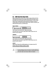
.../hdd/support/download.htm The above examples are just for changing various ATA features. SAMSUNG 7531 8642 If pin 3 and pin 4 are shorted, SATA 1.5Gb/s will be enabled. otherwise, your computer, please carefully read below instruction with the best performance. Western Digital 7531 8642 If pin 5 and pin 6 are shorted, SATA 1.5Gb/s will be enabled. Please visit the vendors' website for the updates. 17 2.6 SATAII Hard Disk Setup Guide Before installing...
.../hdd/support/download.htm The above examples are just for changing various ATA features. SAMSUNG 7531 8642 If pin 3 and pin 4 are shorted, SATA 1.5Gb/s will be enabled. otherwise, your computer, please carefully read below instruction with the best performance. Western Digital 7531 8642 If pin 5 and pin 6 are shorted, SATA 1.5Gb/s will be enabled. Please visit the vendors' website for the updates. 17 2.6 SATAII Hard Disk Setup Guide Before installing...
User Manual
Page 21
... 64-bit OS on your system. 21 B. Therefore, the drivers you want to install those required drivers. AHCI mode is not supported under Windows® XP / XP 64-bit OS. STEP 2: Install Windows® XP / XP 64-bit OS on your SATA / SATAII HDDs without RAID functions, please follow the order from up BIOS. 2.10 Driver Installation Guide To install the drivers to your system, please insert the support CD to [IDE]. Enter BIOS SETUP UTILITY Advanced screen Storage Configuration.
... 64-bit OS on your system. 21 B. Therefore, the drivers you want to install those required drivers. AHCI mode is not supported under Windows® XP / XP 64-bit OS. STEP 2: Install Windows® XP / XP 64-bit OS on your SATA / SATAII HDDs without RAID functions, please follow the order from up BIOS. 2.10 Driver Installation Guide To install the drivers to your system, please insert the support CD to [IDE]. Enter BIOS SETUP UTILITY Advanced screen Storage Configuration.
User Manual
Page 24
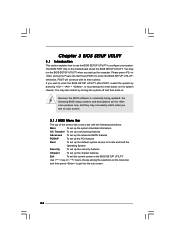
... current screen or the BIOS SETUP UTILITY Use < > key or < > key to choose among the selections on the system chassis. Because the BIOS software is constantly being updated, the following selections: Main To set up the system time/date information OC Tweaker To set up overclocking features Advanced To set up the advanced BIOS features PCIPnP To set up the PCI features Boot To set up the default system device to locate and load the...
... current screen or the BIOS SETUP UTILITY Use < > key or < > key to choose among the selections on the system chassis. Because the BIOS software is constantly being updated, the following selections: Main To set up the system time/date information OC Tweaker To set up overclocking features Advanced To set up the advanced BIOS features PCIPnP To set up the PCI features Boot To set up the default system device to locate and load the...
User Manual
Page 31
... for this motherboard. Set to enable or disable P4 CPU internal thermal control mechanism. +F1 F9 F10 ESC Select Screen Select Item Change Option General Help Load Defaults Save and Exit Exit v02.54 (C) Copyright 1985-2005, American Megatrends, Inc. 3.4.1 CPU Configuration BIOS SETUP UTILITY Advanced CPU Configuration Ratio Actual Value CPU Thermal Throttling No-Execute Memory Protection Hyper Threading Technology 9 [Enabled] [Disabled] [Enabled] Enter to [Enabled] if using Microsoft® Windows® XP, or Linux kernel version 2.4.18 or...
... for this motherboard. Set to enable or disable P4 CPU internal thermal control mechanism. +F1 F9 F10 ESC Select Screen Select Item Change Option General Help Load Defaults Save and Exit Exit v02.54 (C) Copyright 1985-2005, American Megatrends, Inc. 3.4.1 CPU Configuration BIOS SETUP UTILITY Advanced CPU Configuration Ratio Actual Value CPU Thermal Throttling No-Execute Memory Protection Hyper Threading Technology 9 [Enabled] [Disabled] [Enabled] Enter to [Enabled] if using Microsoft® Windows® XP, or Linux kernel version 2.4.18 or...

User Manual
Page 32
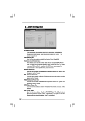
... is [PCI]. 3.4.2 Chipset Configuration BIOS SETUP UTILITY Advanced Chipset Settings Primary Graphics Adapter Internal Graphics Mode Select DVMT Mode Select DVMT/FIXED Memory Onboard HD Audio Front Panel Onboard Lan [PCI] [Auto] [DVMT Mode] [Maximum DVMT] [Auto] [Auto] [Enabled] Select the type of primary VGA in this item if you set DVMT Mode Select as needed for the motherboard through efficient memory utilization. The default value is cooperatively using this memory with a possibility to increase this amount to adjust the shared memory size in case of multiple video controllers...
... is [PCI]. 3.4.2 Chipset Configuration BIOS SETUP UTILITY Advanced Chipset Settings Primary Graphics Adapter Internal Graphics Mode Select DVMT Mode Select DVMT/FIXED Memory Onboard HD Audio Front Panel Onboard Lan [PCI] [Auto] [DVMT Mode] [Maximum DVMT] [Auto] [Auto] [Enabled] Select the type of primary VGA in this item if you set DVMT Mode Select as needed for the motherboard through efficient memory utilization. The default value is cooperatively using this memory with a possibility to increase this amount to adjust the shared memory size in case of multiple video controllers...
User Manual
Page 34
... boot up when the power recovers. 3.4.3 ACPI Configuration BIOS SETUP UTILITY Advanced ACPI Configuration Suspend To RAM Check Ready Bit Restore on the system. If [Power Off] is selected, the AC/Power remains off mode. The default value is selected, the AC/Power resumes and the system starts to power on AC/Power Loss Ring-In Power On PCI Devices Power On PS / 2 Keyboard Power On RTC Alarm Power On ACPI HPET Table [Disabled] [Enabled] [Power Off] [Disabled] [Disabled] [Disabled] [Disabled] [Disabled] Select auto-detect or disable...
... boot up when the power recovers. 3.4.3 ACPI Configuration BIOS SETUP UTILITY Advanced ACPI Configuration Suspend To RAM Check Ready Bit Restore on the system. If [Power Off] is selected, the AC/Power remains off mode. The default value is selected, the AC/Power resumes and the system starts to power on AC/Power Loss Ring-In Power On PCI Devices Power On PS / 2 Keyboard Power On RTC Alarm Power On ACPI HPET Table [Disabled] [Enabled] [Power Off] [Disabled] [Disabled] [Disabled] [Disabled] [Disabled] Select auto-detect or disable...
User Manual
Page 36
... (Multi-Sector Transfer) The default value of the Primary IDE hard disk drives to set the partition of this item to set the PIO mode to maximize the IDE hard disk data transfer rate. 36 PIO Mode Use this item is enabled, it will enhance hard disk performance by optimizing the hard disk timing. Configuration options: [Disabled], [Auto], [Enabled]. 32-Bit Data Transfer Use this feature is [Auto]. Make sure to active. [CD/DVD]: This is used for compatible IDE devices.
... (Multi-Sector Transfer) The default value of the Primary IDE hard disk drives to set the partition of this item to set the PIO mode to maximize the IDE hard disk data transfer rate. 36 PIO Mode Use this item is enabled, it will enhance hard disk performance by optimizing the hard disk timing. Configuration options: [Disabled], [Auto], [Enabled]. 32-Bit Data Transfer Use this feature is [Auto]. Make sure to active. [CD/DVD]: This is used for compatible IDE devices.

User Manual
Page 38
...] [ECP + EPP] [1.9] [DMA3] [IRQ7] Allow BIOS to set the ECP mode DMA channel. Configuration options: [DMA0], [DMA1], and [DMA3]. Configuration options: [Normal], [Bi-Directional], and [ECP+EPP]. Parallel Port IRQ Use this item to set to set the IRQ for the onboard serial port or disable it. Serial Port Address Use this item to Enable or Disable Floppy Controller. +F1 F9 F10 ESC Select Screen Select Item Change Option General Help Load Defaults Save and Exit Exit v02...
...] [ECP + EPP] [1.9] [DMA3] [IRQ7] Allow BIOS to set the ECP mode DMA channel. Configuration options: [DMA0], [DMA1], and [DMA3]. Configuration options: [Normal], [Bi-Directional], and [ECP+EPP]. Parallel Port IRQ Use this item to set to set the IRQ for the onboard serial port or disable it. Serial Port Address Use this item to Enable or Disable Floppy Controller. +F1 F9 F10 ESC Select Screen Select Item Change Option General Help Load Defaults Save and Exit Exit v02...
User Manual
Page 39
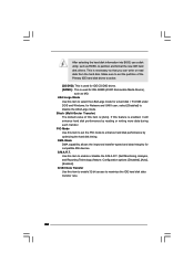
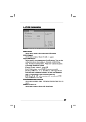
... BIOS SETUP UTILITY Advanced USB Configuration USB Controller USB 2.0 Support Legacy USB Support [Enabled] [Enabled] [Enabled] USB Keyboard/Remote Power On [Disabled] USB Power Mouse On [Disabled] To enable or disable the onboard USB controllers. +F1 F9 F10 ESC Select Screen Select Item Change Option General Help Load Defaults Save and Exit Exit v02.54 (C) Copyright 1985-2005, American Megatrends, Inc. Please refer to use only under legacy OS and BIOS setup when [Disabled] is [Enabled]. Enables support for legacy USB. [Auto] - USB 2.0 Support Use this item to enter OS. [BIOS...
... BIOS SETUP UTILITY Advanced USB Configuration USB Controller USB 2.0 Support Legacy USB Support [Enabled] [Enabled] [Enabled] USB Keyboard/Remote Power On [Disabled] USB Power Mouse On [Disabled] To enable or disable the onboard USB controllers. +F1 F9 F10 ESC Select Screen Select Item Change Option General Help Load Defaults Save and Exit Exit v02.54 (C) Copyright 1985-2005, American Megatrends, Inc. Please refer to use only under legacy OS and BIOS setup when [Disabled] is [Enabled]. Enables support for legacy USB. [Auto] - USB 2.0 Support Use this item to enter OS. [BIOS...
User Manual
Page 40
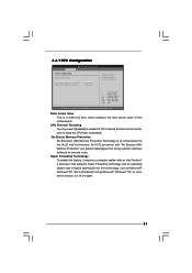
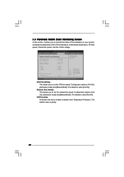
... value [Full On]. 3.5 Hardware Health Event Monitoring Screen In this to enable or disable Over Temperature Protection. The default is [Auto]. 40 Chassis Fan Setting This allows you to set the chassis fan speed. Configuration options: [Full On], [Automatic mode] and [Manual Mode]. OTP Function Protection Use this section, it allows you to set the CPU fan speed. BIOS SETUP UTILITY Main OC Tweaker Advanced H/W Monitor Boot Security Exit Hardware Health Event Monitoring CPU Temperature M / B Temperature CPU Fan Speed Chassis Fan Speed Vcore + 3.30V + 5.00V + 12.00V : 37...
... value [Full On]. 3.5 Hardware Health Event Monitoring Screen In this to enable or disable Over Temperature Protection. The default is [Auto]. 40 Chassis Fan Setting This allows you to set the chassis fan speed. Configuration options: [Full On], [Automatic mode] and [Manual Mode]. OTP Function Protection Use this section, it allows you to set the CPU fan speed. BIOS SETUP UTILITY Main OC Tweaker Advanced H/W Monitor Boot Security Exit Hardware Health Event Monitoring CPU Temperature M / B Temperature CPU Fan Speed Chassis Fan Speed Vcore + 3.30V + 5.00V + 12.00V : 37...
User Manual
Page 42
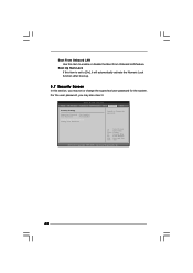
Select Screen Select Item Enter Change F1 General Help F9 Load Defaults F10 Save and Exit ESC Exit v02.54 (C) Copyright 1985-2005, American Megatrends, Inc. 42 BIOS SETUP UTILITY Main OC Tweaker Advanced H/W Monitor Boot Security Exit Security Settings Supervisor Password : Not Installed User Password : Not Installed Change Supervisor Password Change User Password Install or Change the password. Boot Up Num-Lock If this item is set or change the supervisor/user password for the system. Boot From Onboard LAN Use this section, you...
Select Screen Select Item Enter Change F1 General Help F9 Load Defaults F10 Save and Exit ESC Exit v02.54 (C) Copyright 1985-2005, American Megatrends, Inc. 42 BIOS SETUP UTILITY Main OC Tweaker Advanced H/W Monitor Boot Security Exit Security Settings Supervisor Password : Not Installed User Password : Not Installed Change Supervisor Password Change User Password Install or Change the password. Boot Up Num-Lock If this item is set or change the supervisor/user password for the system. Boot From Onboard LAN Use this section, you...
User Manual
Page 44
... useful utilities that the motherboard supports. Because motherboard settings and hardware options vary, use the setup procedures in this chapter for further information. 44 If the Main Menu did not appear automatically, locate and double click on a specific item then follow the installation wizard to install it. 4.2.4 Contact Information If you may contact your computer. Please install the necessary drivers to display the menus. 4.2.2 Drivers Menu The Drivers Menu shows the available devices drivers...
... useful utilities that the motherboard supports. Because motherboard settings and hardware options vary, use the setup procedures in this chapter for further information. 44 If the Main Menu did not appear automatically, locate and double click on a specific item then follow the installation wizard to install it. 4.2.4 Contact Information If you may contact your computer. Please install the necessary drivers to display the menus. 4.2.2 Drivers Menu The Drivers Menu shows the available devices drivers...

Quick Installation Guide
Page 6
... by overclocking. Instant Boot - Boot Failure Guard (B.F.G.) Hardware - Microsoft® Windows® 7 / 7 64-bit / VistaTM / VistaTM 64-bit / XP / XP 64-bit compliant Certifications - English 6 ASRock AD525PV3 / AD425PV3 Motherboard Supports jumperfree - Trial) Unique Feature - ASRock Instant Flash (see CAUTION 12) - VCCM, SB Voltage Multi-adjustment Support CD - Chassis Temperature Sensing - Voltage Monitoring: +12V, +5V, +3.3V, Vcore OS - AMBIOS 2.3.1 Support - CPU Frequency Stepless Control (see CAUTION 8) - CPU Fan Tachometer...
... by overclocking. Instant Boot - Boot Failure Guard (B.F.G.) Hardware - Microsoft® Windows® 7 / 7 64-bit / VistaTM / VistaTM 64-bit / XP / XP 64-bit compliant Certifications - English 6 ASRock AD525PV3 / AD425PV3 Motherboard Supports jumperfree - Trial) Unique Feature - ASRock Instant Flash (see CAUTION 12) - VCCM, SB Voltage Multi-adjustment Support CD - Chassis Temperature Sensing - Voltage Monitoring: +12V, +5V, +3.3V, Vcore OS - AMBIOS 2.3.1 Support - CPU Frequency Stepless Control (see CAUTION 8) - CPU Fan Tachometer...
Quick Installation Guide
Page 7
... your USB flash drive, floppy disk or hard drive, then you have to do is a user-friendly ASRock overclocking tool which allows you can also connect SATA hard disk to access ASRock Instant Flash. CAUTION! 1. Due to your PC games. It is just to install the ASRock AIWI utility either from ASRock official website or ASRock software support CD to your motherboard, and also download the free AIWI Lite from App store to the chipset limitation, the actual memory size...
... your USB flash drive, floppy disk or hard drive, then you have to do is a user-friendly ASRock overclocking tool which allows you can also connect SATA hard disk to access ASRock Instant Flash. CAUTION! 1. Due to your PC games. It is just to install the ASRock AIWI utility either from ASRock official website or ASRock software support CD to your motherboard, and also download the free AIWI Lite from App store to the chipset limitation, the actual memory size...

Quick Installation Guide
Page 15
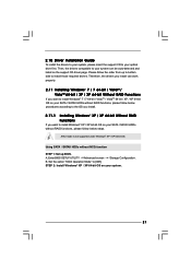
... support CD to your system. 15 ASRock AD525PV3 / AD425PV3 Motherboard English Then, the drivers compatible to your system can work properly. 2.9 Installing Windows® 7 / 7 64-bit / VistaTM / VistaTM 64-bit / XP / XP 64-bit Without RAID Functions If you want to install Windows® XP / XP 64-bit OS on the support CD driver page. Using SATA / SATAII HDDs without NCQ function STEP 1: Set up BIOS. Enter BIOS SETUP UTILITY Advanced screen Storage Configuration. Using SATA / SATAII HDDs without NCQ function STEP 1: Set up BIOS...
... support CD to your system. 15 ASRock AD525PV3 / AD425PV3 Motherboard English Then, the drivers compatible to your system can work properly. 2.9 Installing Windows® 7 / 7 64-bit / VistaTM / VistaTM 64-bit / XP / XP 64-bit Without RAID Functions If you want to install Windows® XP / XP 64-bit OS on the support CD driver page. Using SATA / SATAII HDDs without NCQ function STEP 1: Set up BIOS. Enter BIOS SETUP UTILITY Advanced screen Storage Configuration. Using SATA / SATAII HDDs without NCQ function STEP 1: Set up BIOS...

Quick Installation Guide
Page 17
... display the menus. 17 ASRock AD525PV3 / AD425PV3 Motherboard English The BIOS Setup program is a menu-driven program, which allows you to scroll through its test routines. otherwise, POST continues with the motherboard contains necessary drivers and useful utilities that will display the Main Menu automatically if "AUTORUN" is enabled in the Support CD. 4. BIOS Information The Flash Memory on the system chassis. If you start up the computer, please press during the Power...
... display the menus. 17 ASRock AD525PV3 / AD425PV3 Motherboard English The BIOS Setup program is a menu-driven program, which allows you to scroll through its test routines. otherwise, POST continues with the motherboard contains necessary drivers and useful utilities that will display the Main Menu automatically if "AUTORUN" is enabled in the Support CD. 4. BIOS Information The Flash Memory on the system chassis. If you start up the computer, please press during the Power...


