User Manual
Page 7
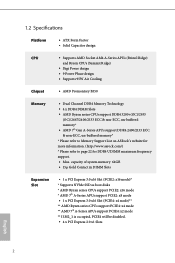
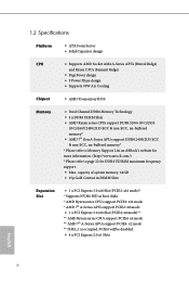
...Factor • Solid Capacitor design CPU • Supports AMD Socket AM4 A-Series APUs (Bristol Ridge) and Ryzen CPUs (Summit Ridge) • Digi Power design • 9 Power Phase design • Supports 95W Air Cooling Chipset • AMD Promontory B350 Memory • Dual Channel DDR4 Memory Technology • 4 x DDR4 ... Gen A-Series APUs support DDR4 2400/2133 ECC & non-ECC, un-buffered memory* * Please refer to Memory Support List on ASRock's website for more information. (http://www.asrock.com/) * Please refer to page 22 for DDR4 UDIMM maximum frequency support. • Max.
...Factor • Solid Capacitor design CPU • Supports AMD Socket AM4 A-Series APUs (Bristol Ridge) and Ryzen CPUs (Summit Ridge) • Digi Power design • 9 Power Phase design • Supports 95W Air Cooling Chipset • AMD Promontory B350 Memory • Dual Channel DDR4 Memory Technology • 4 x DDR4 ... Gen A-Series APUs support DDR4 2400/2133 ECC & non-ECC, un-buffered memory* * Please refer to Memory Support List on ASRock's website for more information. (http://www.asrock.com/) * Please refer to page 22 for DDR4 UDIMM maximum frequency support. • Max.
User Manual
Page 9
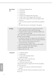
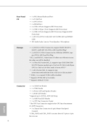
...M.2 SATA3 6.0 Gb/s module** ** If M2_1 is occupied, PCIE4 will be disabled. ** Supports NVMe SSD as boot disks ** Supports ASRock U.2 Kit Connector • 1 x COM Port Header • 1 x TPM Header • 1 x Power LED and Speaker Header • 1 x RGB LED Header * Supports up to 12V/3A, 36W LED Strip • 1 x ... (with LED (ACT/LINK LED and SPEED LED) • HD Audio Jacks: Line in use. 4 English If either one of maximum 1A (12W) fan power. • 3 x Chassis Fan Connectors (4-pin) (Smart Fan Speed Control) * CHA_FAN2 and CHA_FAN3 can auto detect if 3-pin or 4-pin fan is in /...
...M.2 SATA3 6.0 Gb/s module** ** If M2_1 is occupied, PCIE4 will be disabled. ** Supports NVMe SSD as boot disks ** Supports ASRock U.2 Kit Connector • 1 x COM Port Header • 1 x TPM Header • 1 x Power LED and Speaker Header • 1 x RGB LED Header * Supports up to 12V/3A, 36W LED Strip • 1 x ... (with LED (ACT/LINK LED and SPEED LED) • HD Audio Jacks: Line in use. 4 English If either one of maximum 1A (12W) fan power. • 3 x Chassis Fan Connectors (4-pin) (Smart Fan Speed Control) * CHA_FAN2 and CHA_FAN3 can auto detect if 3-pin or 4-pin fan is in /...
User Manual
Page 10
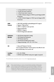
... responsible for details: http://www.asrock.com Certifications • FCC, CE, WHQL • ErP/EuP ready (ErP/EuP ready power supply is required) * For detailed product information, please visit our website: http://www.asrock.com Please realize that there is...+3.3V, Vcore OS • Microsoft® Windows® 10 64-bit * For the updated Windows® 10 driver, please visit ASRock's web- AB350 Pro4 • 1 x 24 pin ATX Power Connector • 1 x 8 pin 12V Power Connector • 1 x Front Panel Audio Connector • 2 x USB 2.0 Headers (Support 4 USB 2.0 ports) (Supports ESD ...
... responsible for details: http://www.asrock.com Certifications • FCC, CE, WHQL • ErP/EuP ready (ErP/EuP ready power supply is required) * For detailed product information, please visit our website: http://www.asrock.com Please realize that there is...+3.3V, Vcore OS • Microsoft® Windows® 10 64-bit * For the updated Windows® 10 driver, please visit ASRock's web- AB350 Pro4 • 1 x 24 pin ATX Power Connector • 1 x 8 pin 12V Power Connector • 1 x Front Panel Audio Connector • 2 x USB 2.0 Headers (Support 4 USB 2.0 ports) (Supports ESD ...
User Manual
Page 12
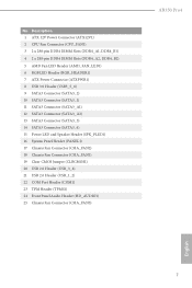
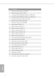
...4 2 x 288-pin DDR4 DIMM Slots (DDR4_A2, DDR4_B2) 5 AMD Fan LED Header (AMD_FAN_LED1) 6 RGB LED Header (RGB_HEADER1) 7 ATX Power Connector (ATXPWR1) 8 USB 3.0 Header (USB3_5_6) 9 SATA3 Connector (SATA3_2) 10 SATA3 Connector (SATA3_1) 11 SATA3 Connector (SATA3_A1) 12 SATA3 ...Connector (SATA3_A2) 13 SATA3 Connector (SATA3_3) 14 SATA3 Connector (SATA3_4) 15 Power LED and Speaker Header (SPK_PLED1) 16 System Panel Header (PANEL1) 17 Chassis Fan Connector (CHA_FAN2) 18 Chassis ... Audio Header (HD_AUDIO1) 25 Chassis Fan Connector (CHA_FAN3) AB350 Pro4 English 7
...4 2 x 288-pin DDR4 DIMM Slots (DDR4_A2, DDR4_B2) 5 AMD Fan LED Header (AMD_FAN_LED1) 6 RGB LED Header (RGB_HEADER1) 7 ATX Power Connector (ATXPWR1) 8 USB 3.0 Header (USB3_5_6) 9 SATA3 Connector (SATA3_2) 10 SATA3 Connector (SATA3_1) 11 SATA3 Connector (SATA3_A1) 12 SATA3 ...Connector (SATA3_A2) 13 SATA3 Connector (SATA3_3) 14 SATA3 Connector (SATA3_4) 15 Power LED and Speaker Header (SPK_PLED1) 16 System Panel Header (PANEL1) 17 Chassis Fan Connector (CHA_FAN2) 18 Chassis ... Audio Header (HD_AUDIO1) 25 Chassis Fan Connector (CHA_FAN3) AB350 Pro4 English 7

User Manual
Page 15
Also remember to unplug the power cord before you handle the components. • Hold components by the edges and do not overtighten the screws! Doing so may cause physical injuries to ...
Also remember to unplug the power cord before you handle the components. • Hold components by the edges and do not overtighten the screws! Doing so may cause physical injuries to ...
User Manual
Page 16
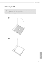
2.1 Installing the CPU Unplug all power cables before installing the CPU. 1 AB350 Pro4 2 English 11
2.1 Installing the CPU Unplug all power cables before installing the CPU. 1 AB350 Pro4 2 English 11
User Manual
Page 18
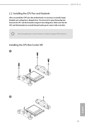
AB350 Pro4 2.2 Installing the CPU Fan and Heatsink After you install the CPU into this motherboard, it is necessary to install a larger heatsink and cooling fan to improve heat dissipation. Please turn off the power or remove the power cord before changing a CPU or heatsink. Installing the CPU Box Cooler SR1 1 2 13 English You also need to spray thermal grease between the CPU and the heatsink to dissipate heat. Make sure that the CPU and the heatsink are securely fastened and in good contact with each other.
AB350 Pro4 2.2 Installing the CPU Fan and Heatsink After you install the CPU into this motherboard, it is necessary to install a larger heatsink and cooling fan to improve heat dissipation. Please turn off the power or remove the power cord before changing a CPU or heatsink. Installing the CPU Box Cooler SR1 1 2 13 English You also need to spray thermal grease between the CPU and the heatsink to dissipate heat. Make sure that the CPU and the heatsink are securely fastened and in good contact with each other.
User Manual
Page 29
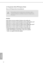
Please read the documentation of the expansion card and make sure that the power supply is switched off or the power cord is unplugged. Before installing an expansion card, please make necessary hardware settings for PCI Express x1 lane width cards. PCIe slots: PCIE1 (PCIe 2.0 x1 ...
Please read the documentation of the expansion card and make sure that the power supply is switched off or the power cord is unplugged. Before installing an expansion card, please make necessary hardware settings for PCI Express x1 lane width cards. PCIe slots: PCIE1 (PCIe 2.0 x1 ...
User Manual
Page 30
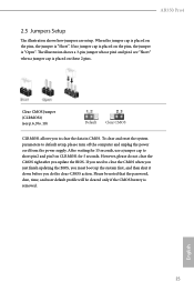
...no jumper cap is placed on CLRMOS1 for 15 seconds, use a jumper cap to default setup, please turn off the computer and unplug the power cord from the power supply. Clear CMOS Jumper (CLRMOS1) (see p.6, No. 19) Default Clear CMOS CLRMOS1 allows you do not clear the CMOS right after you... clear and reset the system parameters to short pin2 and pin3 on the pins, the jumper is "Short". However, please do the clear-CMOS action. AB350 Pro4 2.5 Jumpers Setup The illustration shows how jumpers are "Short" when a jumper cap is placed on the pins, the jumper is "Open". English 25 ...
...no jumper cap is placed on CLRMOS1 for 15 seconds, use a jumper cap to default setup, please turn off the computer and unplug the power cord from the power supply. Clear CMOS Jumper (CLRMOS1) (see p.6, No. 19) Default Clear CMOS CLRMOS1 allows you do not clear the CMOS right after you... clear and reset the system parameters to short pin2 and pin3 on the pins, the jumper is "Short". However, please do the clear-CMOS action. AB350 Pro4 2.5 Jumpers Setup The illustration shows how jumpers are "Short" when a jumper cap is placed on the pins, the jumper is "Open". English 25 ...

User Manual
Page 31
... front panel. The LED is on when the system is reading or writing data. When connecting your system using the power switch. RESET (Reset Switch): Connect to the power status indicator on the chassis front panel. Press the reset switch to restart the computer if the computer freezes and fails...). HDLED (Hard Drive Activity LED): Connect to the pin assignments below. The LED is off when the system is in S4 sleep state or powered off your chassis front panel module to this header according to the hard drive activity LED on the chassis front panel. 2.6 Onboard Headers and Connectors...
... front panel. The LED is on when the system is reading or writing data. When connecting your system using the power switch. RESET (Reset Switch): Connect to the power status indicator on the chassis front panel. Press the reset switch to restart the computer if the computer freezes and fails...). HDLED (Hard Drive Activity LED): Connect to the pin assignments below. The LED is off when the system is in S4 sleep state or powered off your chassis front panel module to this header according to the hard drive activity LED on the chassis front panel. 2.6 Onboard Headers and Connectors...
User Manual
Page 32
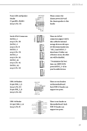
... motherboard. Each USB 3.0 header can support two ports. Each USB 2.0 header can support two ports. 27 Please connect the chassis power LED and the chassis speaker to 6.0 Gb/s data transfer rate. * M2_2 and SATA3_3 share lanes. These six SATA3 connectors support...No. 20) USB 3.0 Header (19-pin USB3_5_6) (see p.6, No. 12) SPEAKER DUMMY DUMMY +5V 1 PLED+ PLED+ PLED- SATA3_1 SATA3_4 SATA3_3 SATA3_A2 SATA3_A1 SATA3_2 English AB350 Pro4 Power LED and Speaker Header (7-pin SPK_PLED1) (see p.6, No. 15) Serial ATA3 Connectors (SATA3_1: see p.6, No. 10) (SATA3_2: see p.6, No. 9) (SATA3_3: see ...
... motherboard. Each USB 3.0 header can support two ports. Each USB 2.0 header can support two ports. 27 Please connect the chassis power LED and the chassis speaker to 6.0 Gb/s data transfer rate. * M2_2 and SATA3_3 share lanes. These six SATA3 connectors support...No. 20) USB 3.0 Header (19-pin USB3_5_6) (see p.6, No. 12) SPEAKER DUMMY DUMMY +5V 1 PLED+ PLED+ PLED- SATA3_1 SATA3_4 SATA3_3 SATA3_A2 SATA3_A1 SATA3_2 English AB350 Pro4 Power LED and Speaker Header (7-pin SPK_PLED1) (see p.6, No. 15) Serial ATA3 Connectors (SATA3_1: see p.6, No. 10) (SATA3_2: see p.6, No. 9) (SATA3_3: see ...
User Manual
Page 34
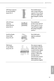
... platform integrity. To use a 4 1 4-pin ATX power supply, please plug it along Pin 1 and Pin 5. To use a 20-pin ATX power supply, please plug it along Pin 1 and Pin 13. 8 5 This motherboard provides a 8-pin ATX 12V power connector. RRXD1 DDTR#1 DDSR#1 CCTS#1 1 RRI#1 RRTS..., which can securely store keys, digital 1 certificates, passwords, PCICLK FRAME PCIRST# LAD3 +3V LAD0 +3VSB GND and data. AB350 Pro4 ATX Power Connector (24-pin ATXPWR1) (see p.6, No. 7) ATX 12V Power Connector (8-pin ATX12V1) (see p.6, No. 1) Serial Port Header (9-pin COM1) (see p.6, No. 22) TPM Header (...
... platform integrity. To use a 4 1 4-pin ATX power supply, please plug it along Pin 1 and Pin 5. To use a 20-pin ATX power supply, please plug it along Pin 1 and Pin 13. 8 5 This motherboard provides a 8-pin ATX 12V power connector. RRXD1 DDTR#1 DDSR#1 CCTS#1 1 RRI#1 RRTS..., which can securely store keys, digital 1 certificates, passwords, PCICLK FRAME PCIRST# LAD3 +3V LAD0 +3VSB GND and data. AB350 Pro4 ATX Power Connector (24-pin ATXPWR1) (see p.6, No. 7) ATX 12V Power Connector (8-pin ATX12V1) (see p.6, No. 1) Serial Port Header (9-pin COM1) (see p.6, No. 22) TPM Header (...

User Manual
Page 49
... damaged. 2. Connecting the LED Strip Connect your system and unplug the power cord from the power supply. Before installing or removing your RGB LED cable, please power off your RGB LED strip to motherboard components. 1. AB350 Pro4 1 B 12V G R RGB_HEADER1 1. The RGB LED header supports standard...cable may cause damages to the RGB LED Header (RGB_HEADER1) on the motherboard. 3.3 ASRock RGB LED ASRock RGB LED is a lighting control utility specifically designed for unique individuals with a maximum power rating of 3A (12V) and length within 2 meters. 44 English Never install ...
... damaged. 2. Connecting the LED Strip Connect your system and unplug the power cord from the power supply. Before installing or removing your RGB LED cable, please power off your RGB LED strip to motherboard components. 1. AB350 Pro4 1 B 12V G R RGB_HEADER1 1. The RGB LED header supports standard...cable may cause damages to the RGB LED Header (RGB_HEADER1) on the motherboard. 3.3 ASRock RGB LED ASRock RGB LED is a lighting control utility specifically designed for unique individuals with a maximum power rating of 3A (12V) and length within 2 meters. 44 English Never install ...
User Manual
Page 51
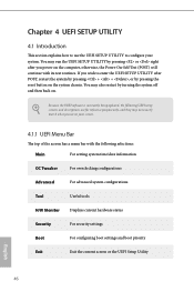
... English 46 Chapter 4 UEFI SETUP UTILITY 4.1 Introduction This section explains how to use the UEFI SETUP UTILITY to enter the UEFI SETUP UTILITY after you power on . If you wish to configure your screen. 4.1.1 UEFI Menu Bar The top of the screen has a menu bar with its test routines.... or right after POST, restart the system by pressing + + , or by turning the system off and then back on the computer, otherwise, the Power-On-Self-Test (POST) will continue with the following UEFI setup screens and descriptions are for reference purpose only, and they may not exactly match...
... English 46 Chapter 4 UEFI SETUP UTILITY 4.1 Introduction This section explains how to use the UEFI SETUP UTILITY to enter the UEFI SETUP UTILITY after you power on . If you wish to configure your screen. 4.1.1 UEFI Menu Bar The top of the screen has a menu bar with its test routines.... or right after POST, restart the system by pressing + + , or by turning the system off and then back on the computer, otherwise, the Power-On-Self-Test (POST) will continue with the following UEFI setup screens and descriptions are for reference purpose only, and they may not exactly match...
User Manual
Page 57
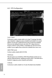
... Use this item to enable or disable Core C6 mode. C6 Mode Use this to system stability or compatibility issue with some memory modules or power supplies. The default value is [Enabled]. The default value is [Enabled]. SVM Mode When this function may reduce CPU voltage and memory frequency, and lead...
... Use this item to enable or disable Core C6 mode. C6 Mode Use this to system stability or compatibility issue with some memory modules or power supplies. The default value is [Enabled]. The default value is [Enabled]. SVM Mode When this function may reduce CPU voltage and memory frequency, and lead...

User Manual
Page 59
Deep Sleep Configure deep sleep mode for power saving when the computer is selected, the power will start to boot up when the power recovers. 54 English If [Power Off] is shut down. Front Panel Enable/disable front panel HD audio. Restore on AC/Power Loss Select the power state after a power failure. Set to Auto to enable onboard HD audio and automatically disable it when a sound card is selected, the system will remain off when the power recovers. If [Power On] is installed. 4.4.3 South Bridge Configuration Onboard HD Audio Enable/disable onboard HD audio.
Deep Sleep Configure deep sleep mode for power saving when the computer is selected, the power will start to boot up when the power recovers. 54 English If [Power Off] is shut down. Front Panel Enable/disable front panel HD audio. Restore on AC/Power Loss Select the power state after a power failure. Set to Auto to enable onboard HD audio and automatically disable it when a sound card is selected, the system will remain off when the power recovers. If [Power On] is installed. 4.4.3 South Bridge Configuration Onboard HD Audio Enable/disable onboard HD audio.
User Manual
Page 62
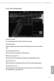
... time clock alarm. PCIE Devices Power On Allow the system to be waked up by a PCIE device and enable wake on LAN. Set it to By OS to select auto for better performance and to be waked up by a PS/2 Keyboard. 4.4.6 ACPI Configuration AB350 Pro4 Suspend to RAM It is recommended... to let it be handled by your operating system. 57 English PS/2 Keyboard Power On Allow the system to be waked up by onboard COM port modem Ring-In signals.
... time clock alarm. PCIE Devices Power On Allow the system to be waked up by a PCIE device and enable wake on LAN. Set it to By OS to select auto for better performance and to be waked up by a PS/2 Keyboard. 4.4.6 ACPI Configuration AB350 Pro4 Suspend to RAM It is recommended... to let it be handled by your operating system. 57 English PS/2 Keyboard Power On Allow the system to be waked up by onboard COM port modem Ring-In signals.
Quick Installation Guide
Page 4
... (DDR4_A1, DDR4_B1) 4 2 x 288-pin DDR4 DIMM Slots (DDR4_A2, DDR4_B2) 5 AMD Fan LED Header (AMD_FAN_LED1) 6 RGB LED Header (RGB_HEADER1) 7 ATX Power Connector (ATXPWR1) 8 USB 3.0 Header (USB3_5_6) 9 SATA3 Connector (SATA3_2) 10 SATA3 Connector (SATA3_1) 11 SATA3 Connector (SATA3_A1) 12 SATA3 Connector (SATA3_A2) 13... SATA3 Connector (SATA3_3) 14 SATA3 Connector (SATA3_4) 15 Power LED and Speaker Header (SPK_PLED1) 16 System Panel Header (PANEL1) 17 Chassis Fan Connector (CHA_FAN2) 18 Chassis Fan Connector (CHA_FAN1)...
... (DDR4_A1, DDR4_B1) 4 2 x 288-pin DDR4 DIMM Slots (DDR4_A2, DDR4_B2) 5 AMD Fan LED Header (AMD_FAN_LED1) 6 RGB LED Header (RGB_HEADER1) 7 ATX Power Connector (ATXPWR1) 8 USB 3.0 Header (USB3_5_6) 9 SATA3 Connector (SATA3_2) 10 SATA3 Connector (SATA3_1) 11 SATA3 Connector (SATA3_A1) 12 SATA3 Connector (SATA3_A2) 13... SATA3 Connector (SATA3_3) 14 SATA3 Connector (SATA3_4) 15 Power LED and Speaker Header (SPK_PLED1) 16 System Panel Header (PANEL1) 17 Chassis Fan Connector (CHA_FAN2) 18 Chassis Fan Connector (CHA_FAN1)...
Quick Installation Guide
Page 8
...Factor • Solid Capacitor design CPU • Supports AMD Socket AM4 A-Series APUs (Bristol Ridge) and Ryzen CPUs (Summit Ridge) • Digi Power design • 9 Power Phase design • Supports 95W Air Cooling Chipset • AMD Promontory B350 Memory • Dual Channel DDR4 Memory Technology • 4 x DDR4 ...7th Gen A-Series APUs support DDR4 2400/2133 ECC & non-ECC, un-buffered memory* * Please refer to Memory Support List on ASRock's website for more information. (http://www.asrock.com/) * Please refer to page 22 for DDR4 UDIMM maximum frequency support. • Max.
...Factor • Solid Capacitor design CPU • Supports AMD Socket AM4 A-Series APUs (Bristol Ridge) and Ryzen CPUs (Summit Ridge) • Digi Power design • 9 Power Phase design • Supports 95W Air Cooling Chipset • AMD Promontory B350 Memory • Dual Channel DDR4 Memory Technology • 4 x DDR4 ...7th Gen A-Series APUs support DDR4 2400/2133 ECC & non-ECC, un-buffered memory* * Please refer to Memory Support List on ASRock's website for more information. (http://www.asrock.com/) * Please refer to page 22 for DDR4 UDIMM maximum frequency support. • Max.
Quick Installation Guide
Page 10
...either one of them is in use, the other one will be disabled. ** Supports NVMe SSD as boot disks ** Supports ASRock U.2 Kit Connector • 1 x COM Port Header • 1 x TPM Header • 1 x Power LED and Speaker Header • 1 x RGB LED Header * Supports up to 12V/3A, 36W LED Strip • 1... x AMD Fan LED Header • 1 x CPU Fan Connector (4-pin) * The CPU Fan Connector supports the CPU fan of maximum 1A (12W) fan power. • 3 x Chassis Fan Connectors (4-pin) (Smart Fan Speed Control) * CHA_FAN2 and CHA_FAN3 can auto detect if 3-pin or 4-pin fan is in / Front ...
...either one of them is in use, the other one will be disabled. ** Supports NVMe SSD as boot disks ** Supports ASRock U.2 Kit Connector • 1 x COM Port Header • 1 x TPM Header • 1 x Power LED and Speaker Header • 1 x RGB LED Header * Supports up to 12V/3A, 36W LED Strip • 1... x AMD Fan LED Header • 1 x CPU Fan Connector (4-pin) * The CPU Fan Connector supports the CPU fan of maximum 1A (12W) fan power. • 3 x Chassis Fan Connectors (4-pin) (Smart Fan Speed Control) * CHA_FAN2 and CHA_FAN3 can auto detect if 3-pin or 4-pin fan is in / Front ...


