User Manual
Page 6
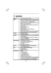
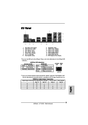
... (see CAUTION 2) - 4 x DDR2 DIMM slots - Supports AMD OverDriveTM with LED (ACT/LINK LED and SPEED LED) - 1.2 Specifications Platform CPU Chipset Memory Expansion Slot Audio LAN Rear Panel I /O Panel - 1 x PS/2 Mouse Port - 1 x PS/2 Keyboard Port - 1 x Coaxial SPDIF Out Port - 1 x Optical SPDIF Out... Port - 6 x Ready-to 140W - FSB 2600 MHz (5.2 GT/s) - Southbridge: AMD SB710 - HD Audio Jack: Side Speaker/Rear Speaker/Central/Bass/ Line in , 30.5 cm x 20.8 cm - Support for AM3 processors: AMD PhenomTM II X4 / X3 and Athlon ...
... (see CAUTION 2) - 4 x DDR2 DIMM slots - Supports AMD OverDriveTM with LED (ACT/LINK LED and SPEED LED) - 1.2 Specifications Platform CPU Chipset Memory Expansion Slot Audio LAN Rear Panel I /O Panel - 1 x PS/2 Mouse Port - 1 x PS/2 Keyboard Port - 1 x Coaxial SPDIF Out Port - 1 x Optical SPDIF Out... Port - 6 x Ready-to 140W - FSB 2600 MHz (5.2 GT/s) - Southbridge: AMD SB710 - HD Audio Jack: Side Speaker/Rear Speaker/Central/Bass/ Line in , 30.5 cm x 20.8 cm - Support for AM3 processors: AMD PhenomTM II X4 / X3 and Athlon ...

User Manual
Page 7
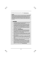
...audio connector - 3 x USB 2.0 headers (support 6 USB 2.0 ports) (see CAUTION 11) - AMI Legal BIOS - Supports Smart BIOS - Instant Boot - ASRock U-COP (see CAUTION 7) - 8Mb AMI BIOS - Supports "Plug and Play" - Supports jumperfree - Hybrid Booster: - Boot Failure Guard (B.F.G.) - CPU Temperature Sensing - CPU Quiet Fan - Voltage Monitoring: +12V, +5V, +3.3V, Vcore - ASRock...AMD OverDriveTM Utility - CD in header - CPU, NB, SB, VCCM Voltage Multi-adjustment - ASRock AM2 Boost: ASRock Patented Technology to boost memory performance up to 12.5% (see CAUTION 6) - 1 x ATA133 IDE...
...audio connector - 3 x USB 2.0 headers (support 6 USB 2.0 ports) (see CAUTION 11) - AMI Legal BIOS - Supports Smart BIOS - Instant Boot - ASRock U-COP (see CAUTION 7) - 8Mb AMI BIOS - Supports "Plug and Play" - Supports jumperfree - Hybrid Booster: - Boot Failure Guard (B.F.G.) - CPU Temperature Sensing - CPU Quiet Fan - Voltage Monitoring: +12V, +5V, +3.3V, Vcore - ASRock...AMD OverDriveTM Utility - CD in header - CPU, NB, SB, VCCM Voltage Multi-adjustment - ASRock AM2 Boost: ASRock Patented Technology to boost memory performance up to 12.5% (see CAUTION 6) - 1 x ATA133 IDE...
User Manual
Page 8
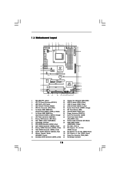
...Channel Memory Technology. Please check the table on page 36 for system usage under Windows® XP and Windows® VistaTM. ASRock website: http://www.asrock.com 8 Overclocking may be done at your SATAII hard disk drive to adjust your own risk and expense. Please read the ...there is a certain risk involved with 64-bit CPU, there is no such limitation. 5. For audio output, this motherboard supports both stereo and mono modes. It is a user-friendly ASRock overclocking tool which allows you want to adopt DDR2 1066 memory module on this motherboard, please refer to...
...Channel Memory Technology. Please check the table on page 36 for system usage under Windows® XP and Windows® VistaTM. ASRock website: http://www.asrock.com 8 Overclocking may be done at your SATAII hard disk drive to adjust your own risk and expense. Please read the ...there is a certain risk involved with 64-bit CPU, there is no such limitation. 5. For audio output, this motherboard supports both stereo and mono modes. It is a user-friendly ASRock overclocking tool which allows you want to adopt DDR2 1066 memory module on this motherboard, please refer to...
User Manual
Page 10
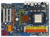
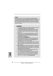
... IN PWR_FAN1 LAN PHY RoHS HT3.0 PCIE1 AMD 770 Chipset PCI Express 2.0 PCIE2 CMOS BATTERY CLRCMOS1 1 Super I/O AUDIO CODEC HDMI_SPDIF1 1 CD1 HD_AUDIO1 1 1 COM1 PCIE3 A770DE+ PCI1 AMD SB710 Chipset PCI2 8Mb BIOS PCI3 FLOPPY1 IR1 1 USB10_11 1 PANEL 1 PLED PWRBTN 1 HDLED RESET ... 27 Serial Port Connector (COM1) 8 ATX Power Connector (ATXPWR1) 28 Front Panel Audio Header 9 Primary IDE Connector (IDE1, Blue) (HD_AUDIO1, Lime) 10 Clear CMOS Jumper (CLRCMOS1) 29 Internal Audio Connector: CD1 (Black) 11 Southbridge Controller 30 HDMI_SPDIF Header 12 Fifth SATAII Connector (...
... IN PWR_FAN1 LAN PHY RoHS HT3.0 PCIE1 AMD 770 Chipset PCI Express 2.0 PCIE2 CMOS BATTERY CLRCMOS1 1 Super I/O AUDIO CODEC HDMI_SPDIF1 1 CD1 HD_AUDIO1 1 1 COM1 PCIE3 A770DE+ PCI1 AMD SB710 Chipset PCI2 8Mb BIOS PCI3 FLOPPY1 IR1 1 USB10_11 1 PANEL 1 PLED PWRBTN 1 HDLED RESET ... 27 Serial Port Connector (COM1) 8 ATX Power Connector (ATXPWR1) 28 Front Panel Audio Header 9 Primary IDE Connector (IDE1, Blue) (HD_AUDIO1, Lime) 10 Clear CMOS Jumper (CLRCMOS1) 29 Internal Audio Connector: CD1 (Black) 11 Southbridge Controller 30 HDMI_SPDIF Header 12 Fifth SATAII Connector (...

User Manual
Page 11
... LAN Port ** If you use 2-channel speaker, please connect the speaker's plug into "Front Speaker Jack". Please refer to the LAN port. TABLE for Audio Output Connection Audio Output Channels Front Speaker Rear Speaker Central / Bass Side Speaker (No. 7) (No. 4) (No. 5) (No. 3) 2 V -- -- -- 4 V V -- -- 6 V V V -- 8 V V V V 11 See the table below for the LAN port LED...
... LAN Port ** If you use 2-channel speaker, please connect the speaker's plug into "Front Speaker Jack". Please refer to the LAN port. TABLE for Audio Output Connection Audio Output Channels Front Speaker Rear Speaker Central / Bass Side Speaker (No. 7) (No. 4) (No. 5) (No. 3) 2 V -- -- -- 4 V V -- -- 6 V V V -- 8 V V V V 11 See the table below for the LAN port LED...

User Manual
Page 12
...® XP / XP 64-bit OS: Please click "VIA HD Audio Deck" icon , and click "Speaker". You can only choose to the front panel audio header. To enable Multi-Streaming function, you need to connect a front panel audio cable to enable either Multi-Streaming function or Side Speaker function. 12...are allowed to the OS you install. If you will be disabled. For Windows® VistaTM / VistaTM 64-bit OS: Please click "VIA HD Audio Deck" icon , and click "Advanced Options" on the left side on your computer, you enable Multi-Streaming function, Side Speaker function will find ...
...® XP / XP 64-bit OS: Please click "VIA HD Audio Deck" icon , and click "Speaker". You can only choose to the front panel audio header. To enable Multi-Streaming function, you need to connect a front panel audio cable to enable either Multi-Streaming function or Side Speaker function. 12...are allowed to the OS you install. If you will be disabled. For Windows® VistaTM / VistaTM 64-bit OS: Please click "VIA HD Audio Deck" icon , and click "Advanced Options" on the left side on your computer, you enable Multi-Streaming function, Side Speaker function will find ...
User Manual
Page 24
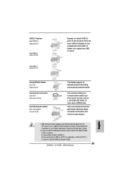
... p.10, No. 28) GND PRESENCE# MIC_RET OUT_RET 1 OUT2_L J_SENSE OUT2_R MIC2_R MIC2_L This is an interface for the front panel audio cable that allows convenient connection and control of audio devices. 1. Connect Mic_IN (MIC) to Ground (GND). 24 USB 2.0 Headers (9-pin USB10_11) (see p.10 No. 22) ... USB 2.0 ports on the I/O panel, there are three USB 2.0 headers on the chassis must support HDA to function correctly. Front Panel Audio Header (9-pin HD_AUDIO1) (see p.10 No. 25) IRTX +5V DUMMY 1 GND IRRX This header supports an optional wireless transmitting and receiving...
... p.10, No. 28) GND PRESENCE# MIC_RET OUT_RET 1 OUT2_L J_SENSE OUT2_R MIC2_R MIC2_L This is an interface for the front panel audio cable that allows convenient connection and control of audio devices. 1. Connect Mic_IN (MIC) to Ground (GND). 24 USB 2.0 Headers (9-pin USB10_11) (see p.10 No. 22) ... USB 2.0 ports on the I/O panel, there are three USB 2.0 headers on the chassis must support HDA to function correctly. Front Panel Audio Header (9-pin HD_AUDIO1) (see p.10 No. 25) IRTX +5V DUMMY 1 GND IRRX This header supports an optional wireless transmitting and receiving...
User Manual
Page 25
...No. 5) FAN_SPEED_CONTROL 4 CPU_FAN_SPEED 3 +12V 2 GND 1 Please connect the CPU fan cable to this motherboard, please connect it to connect them for HD audio panel only. Enter BIOS Setup Utility. E. Please connect the fan cables to the fan connectors and match the black wire to the ground pin. You... to the CPU fan connector on this connector and match the black wire to the ground pin. D. MIC_RET and OUT_RET are for AC'97 audio panel. Pin 1-3 Connected 3-Pin Fan Installation ATX Power Connector (24-pin ATXPWR1) (see p.10 No. 35) PWR_FAN_SPEED +12V GND This ...
...No. 5) FAN_SPEED_CONTROL 4 CPU_FAN_SPEED 3 +12V 2 GND 1 Please connect the CPU fan cable to this motherboard, please connect it to connect them for HD audio panel only. Enter BIOS Setup Utility. E. Please connect the fan cables to the fan connectors and match the black wire to the ground pin. You... to the CPU fan connector on this connector and match the black wire to the ground pin. D. MIC_RET and OUT_RET are for AC'97 audio panel. Pin 1-3 Connected 3-Pin Fan Installation ATX Power Connector (24-pin ATXPWR1) (see p.10 No. 35) PWR_FAN_SPEED +12V GND This ...
User Manual
Page 26
... 13. 20-Pin ATX Power Supply Installation 1 13 ATX 12V Power Connector (8-pin ATX12V1) (see p.10 No. 30) 1 GND SPDIFOUT +5V HDMI_SPDIF header, providing SPDIF audio output to HDMI VGA card, allows the system to connect HDMI Digital TV/ projector/LCD devices. Please connect the HDMI_SPDIF connector of HDMI VGA card...
... 13. 20-Pin ATX Power Supply Installation 1 13 ATX 12V Power Connector (8-pin ATX12V1) (see p.10 No. 30) 1 GND SPDIFOUT +5V HDMI_SPDIF header, providing SPDIF audio output to HDMI VGA card, allows the system to connect HDMI Digital TV/ projector/LCD devices. Please connect the HDMI_SPDIF connector of HDMI VGA card...

User Manual
Page 28
...VGA card and a HDMI ready motherboard with a HDMI_SPDIF header, which provides an interface between any compatible digital audio/video source, such as a set-top box, DVD player, A/V receiver and a compatible digital audio or video monitor, such as HDTV. white end (2-pin) (B) white end (3-pin) (C) Please do ... HDMI VGA card, please refer to connect HDMI Digital TV/projector/ LCD devices. This motherboard is an all-digital audio/video specification, which provides SPDIF audio output to HDMI VGA card, allows the system to the installation guide on this motherboard and the HDMI VGA card....
...VGA card and a HDMI ready motherboard with a HDMI_SPDIF header, which provides an interface between any compatible digital audio/video source, such as a set-top box, DVD player, A/V receiver and a compatible digital audio or video monitor, such as HDTV. white end (2-pin) (B) white end (3-pin) (C) Please do ... HDMI VGA card, please refer to connect HDMI Digital TV/projector/ LCD devices. This motherboard is an all-digital audio/video specification, which provides SPDIF audio output to HDMI VGA card, allows the system to the installation guide on this motherboard and the HDMI VGA card....
User Manual
Page 48
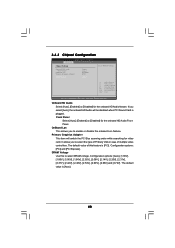
...[2.20V], [2.31V], [2.37V], [2.42V], [2.48V], [2.54V], [2.60V], [2.66V] and [2.72V]. 3.4.3 Chipset Configuration BIOS SETUP UTILITY Advanced Chipset Settings Onboard HD Audio Front Panel OnBoard Lan Primary Graphics Adapter DRAM Voltage [Auto] [Auto] [Enabled] [PCI] [Auto] To set DRAM Voltage. +F1 F9 F10 ESC Select Screen ... [PCI]. The default value of multiple video controllers. Onboard HD Audio Select [Auto], [Enabled] or [Disabled] for the onboard HD Audio Front Panel. If you select [Auto], the onboard HD Audio will switch the PCI Bus scanning order while searching for video card...
...[2.20V], [2.31V], [2.37V], [2.42V], [2.48V], [2.54V], [2.60V], [2.66V] and [2.72V]. 3.4.3 Chipset Configuration BIOS SETUP UTILITY Advanced Chipset Settings Onboard HD Audio Front Panel OnBoard Lan Primary Graphics Adapter DRAM Voltage [Auto] [Auto] [Enabled] [PCI] [Auto] To set DRAM Voltage. +F1 F9 F10 ESC Select Screen ... [PCI]. The default value of multiple video controllers. Onboard HD Audio Select [Auto], [Enabled] or [Disabled] for the onboard HD Audio Front Panel. If you select [Auto], the onboard HD Audio will switch the PCI Bus scanning order while searching for video card...

Quick Installation Guide
Page 2
... (PCIE2; Green) (SPEAKER 1, Purple) 35 Power Fan Connector (PWR_FAN1) 18 Secondary SATAII Connector (SATAII_2, Red) 36 Northbridge Controller 2 ASRock A770DE+ Motherboard Green) 17 Chassis Speaker Header 34 PCI Express x1 Slot (PCIE1; Yellow) 25 Infrared Module Header (IR1) 7 2 x 240... 27 Serial Port Connector (COM1) 8 ATX Power Connector (ATXPWR1) 28 Front Panel Audio Header 9 Primary IDE Connector (IDE1, Blue) (HD_AUDIO1, Lime) 10 Clear CMOS Jumper (CLRCMOS1) 29 Internal Audio Connector: CD1 (Black) 11 Southbridge Controller 30 HDMI_SPDIF Header 12 Fifth SATAII Connector (...
... (PCIE2; Green) (SPEAKER 1, Purple) 35 Power Fan Connector (PWR_FAN1) 18 Secondary SATAII Connector (SATAII_2, Red) 36 Northbridge Controller 2 ASRock A770DE+ Motherboard Green) 17 Chassis Speaker Header 34 PCI Express x1 Slot (PCIE1; Yellow) 25 Infrared Module Header (IR1) 7 2 x 240... 27 Serial Port Connector (COM1) 8 ATX Power Connector (ATXPWR1) 28 Front Panel Audio Header 9 Primary IDE Connector (IDE1, Blue) (HD_AUDIO1, Lime) 10 Clear CMOS Jumper (CLRCMOS1) 29 Internal Audio Connector: CD1 (Black) 11 Southbridge Controller 30 HDMI_SPDIF Header 12 Fifth SATAII Connector (...
Quick Installation Guide
Page 3
...'s plug into "Front Speaker Jack". See the table below for the LAN port LED indications. TABLE for Audio Output Connection Audio Output Channels Front Speaker Rear Speaker Central / Bass Side Speaker (No. 7) (No. 4) (No. 5) (No. 3) 2 V -- -- -- 4 V V -- -- 6 V V V -- 8 V V V V 3 ASRock A770DE+ Motherboard English I/O Panel 1 PS/2 Mouse Port (Green) * 2 LAN RJ-45 Port (LAN1) 3 Side Speaker (Gray) 4 Rear Speaker...
...'s plug into "Front Speaker Jack". See the table below for the LAN port LED indications. TABLE for Audio Output Connection Audio Output Channels Front Speaker Rear Speaker Central / Bass Side Speaker (No. 7) (No. 4) (No. 5) (No. 3) 2 V -- -- -- 4 V V -- -- 6 V V V -- 8 V V V V 3 ASRock A770DE+ Motherboard English I/O Panel 1 PS/2 Mouse Port (Green) * 2 LAN RJ-45 Port (LAN1) 3 Side Speaker (Gray) 4 Rear Speaker...
Quick Installation Guide
Page 4
...will be disabled. If you need to connect a front panel audio cable to select "2 Channel", "4 Channel", "6 Channel" or "8 Channel". You can only choose to the OS you install. English 4 ASRock A770DE+ Motherboard To enable Multi-Streaming function, you enable Multi-Streaming function..., Side Speaker function will find "VIA HD Audio Deck" tool on the bottom. Please follow below instructions according to enable ...
...will be disabled. If you need to connect a front panel audio cable to select "2 Channel", "4 Channel", "6 Channel" or "8 Channel". You can only choose to the OS you install. English 4 ASRock A770DE+ Motherboard To enable Multi-Streaming function, you enable Multi-Streaming function..., Side Speaker function will find "VIA HD Audio Deck" tool on the bottom. Please follow below instructions according to enable ...
Quick Installation Guide
Page 6
... Speaker/Microphone (see CAUTION 3) - HD Audio Jack: Side Speaker/Rear Speaker/Central/Bass/ Line in , 30.5 cm x 20.8 cm - FSB 2600 MHz (5.2 GT/s) - Support DDR2 1066/800/667/533 non-ECC, un-buffered memory (see CAUTION 5) ASRock A770DE+ Motherboard English Supports Untied Overclocking Technology (see...CPU up to -Use USB 2.0 Ports - 1 x RJ-45 LAN Port with ACC feature (Advanced Clock Calibration) - 1.2 Specifications Platform CPU Chipset Memory Expansion Slot Audio LAN Rear Panel I /O Panel - 1 x PS/2 Mouse Port - 1 x PS/2 Keyboard Port - 1 x Coaxial SPDIF Out Port - 1 x Optical...
... Speaker/Microphone (see CAUTION 3) - HD Audio Jack: Side Speaker/Rear Speaker/Central/Bass/ Line in , 30.5 cm x 20.8 cm - FSB 2600 MHz (5.2 GT/s) - Support DDR2 1066/800/667/533 non-ECC, un-buffered memory (see CAUTION 5) ASRock A770DE+ Motherboard English Supports Untied Overclocking Technology (see...CPU up to -Use USB 2.0 Ports - 1 x RJ-45 LAN Port with ACC feature (Advanced Clock Calibration) - 1.2 Specifications Platform CPU Chipset Memory Expansion Slot Audio LAN Rear Panel I /O Panel - 1 x PS/2 Mouse Port - 1 x PS/2 Keyboard Port - 1 x Coaxial SPDIF Out Port - 1 x Optical...

Quick Installation Guide
Page 7
... header - 1 x HDMI_SPDIF header - CPU Temperature Sensing - CPU/Chassis/Power Fan Tachometer - FCC, CE, Microsoft® WHQL Certificated 7 ASRock A770DE+ Motherboard English SMBIOS 2.3.1 Support - Chassis Temperature Sensing - Connector BIOS Feature Support CD Unique Feature Hardware Monitor OS Certifications - 6 x Serial ...XP 64-bit / VistaTM / VistaTM 64-bit compliant - Boot Failure Guard (B.F.G.) - Instant Boot - ASRock U-COP (see CAUTION 12) - Hybrid Booster: - Front panel audio connector - 3 x USB 2.0 headers (support 6 USB 2.0 ports) (see CAUTION 8) - CPU/...
... header - 1 x HDMI_SPDIF header - CPU Temperature Sensing - CPU/Chassis/Power Fan Tachometer - FCC, CE, Microsoft® WHQL Certificated 7 ASRock A770DE+ Motherboard English SMBIOS 2.3.1 Support - Chassis Temperature Sensing - Connector BIOS Feature Support CD Unique Feature Hardware Monitor OS Certifications - 6 x Serial ...XP 64-bit / VistaTM / VistaTM 64-bit compliant - Boot Failure Guard (B.F.G.) - Instant Boot - ASRock U-COP (see CAUTION 12) - Hybrid Booster: - Front panel audio connector - 3 x USB 2.0 headers (support 6 USB 2.0 ports) (see CAUTION 8) - CPU/...
Quick Installation Guide
Page 8
... can also connect SATA hard disk to get the best system performance under Windows® XP and Windows® VistaTM. ASRock website: http://www.asrock.com 8 ASRock A770DE+ Motherboard English Overclocking may be done at your system stability, or even cause damage to the memory support list on page... is a certain risk involved with overclocking, including adjusting the setting in the support CD to adjust your system by overclocking. For audio output, this motherboard supports both stereo and mono modes. Please read the "SATAII Hard Disk Setup Guide" on page 26 for the...
... can also connect SATA hard disk to get the best system performance under Windows® XP and Windows® VistaTM. ASRock website: http://www.asrock.com 8 ASRock A770DE+ Motherboard English Overclocking may be done at your system stability, or even cause damage to the memory support list on page... is a certain risk involved with overclocking, including adjusting the setting in the support CD to adjust your system by overclocking. For audio output, this motherboard supports both stereo and mono modes. Please read the "SATAII Hard Disk Setup Guide" on page 26 for the...
Quick Installation Guide
Page 21
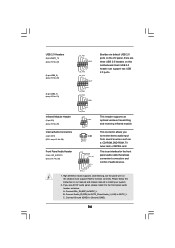
... manual to MIC2_L. If you CD1 to function correctly. B. Infrared Module Header (5-pin IR1) (see p.2 No. 25) Internal Audio Connectors (4-pin CD1) (CD1: see p.2 No. 29) Front Panel Audio Header (9-pin HD_AUDIO1) (see p.2 No. 21) Besides six default USB 2.0 ports on the I/O panel, there are three USB... supports an optional wireless transmitting and receiving infrared module. Connect Audio_R (RIN) to OUT2_R and Audio_L (LIN) to Ground (GND). 21 ASRock A770DE+ Motherboard English C. Connect Ground (GND) to OUT2_L. Each USB 2.0 header can support two USB 2.0 ports.
... manual to MIC2_L. If you CD1 to function correctly. B. Infrared Module Header (5-pin IR1) (see p.2 No. 25) Internal Audio Connectors (4-pin CD1) (CD1: see p.2 No. 29) Front Panel Audio Header (9-pin HD_AUDIO1) (see p.2 No. 21) Besides six default USB 2.0 ports on the I/O panel, there are three USB... supports an optional wireless transmitting and receiving infrared module. Connect Audio_R (RIN) to OUT2_R and Audio_L (LIN) to Ground (GND). 21 ASRock A770DE+ Motherboard English C. Connect Ground (GND) to OUT2_L. Each USB 2.0 header can support two USB 2.0 ports.

Quick Installation Guide
Page 22
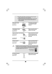
...19) Please connect the fan cables to the fan connectors and match the black wire to connect them for HD audio panel only. MIC_RET and OUT_RET are for AC'97 audio panel. System Panel Header (9-pin PANEL1) (see p.2 No. 5) Please connect the CPU fan 4 cable to ... BIOS Setup Utility. Though this motherboard, please connect it to this header. Set the Front Panel Control option from [Auto] to this connector. 22 ASRock A770DE+ Motherboard English Chassis Speaker Header (4-pin SPEAKER 1) (see p.2 No. 8) 12 24 1 13 Please connect an ATX power supply to Pin 1-3. ...
...19) Please connect the fan cables to the fan connectors and match the black wire to connect them for HD audio panel only. MIC_RET and OUT_RET are for AC'97 audio panel. System Panel Header (9-pin PANEL1) (see p.2 No. 5) Please connect the CPU fan 4 cable to ... BIOS Setup Utility. Though this motherboard, please connect it to this header. Set the Front Panel Control option from [Auto] to this connector. 22 ASRock A770DE+ Motherboard English Chassis Speaker Header (4-pin SPEAKER 1) (see p.2 No. 8) 12 24 1 13 Please connect an ATX power supply to Pin 1-3. ...

Quick Installation Guide
Page 23
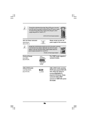
on English 23 ASRock A770DE+ Motherboard HDMI_SPDIF Header (3-pin HDMI_SPDIF1) (see p.2 No. 30) HDMI_SPDIF header, providing SPDIF audio output to HDMI VGA card, allows the system to this motherboard provides 24-pin ATX power connector, 12 24 it can still work if you ...
on English 23 ASRock A770DE+ Motherboard HDMI_SPDIF Header (3-pin HDMI_SPDIF1) (see p.2 No. 30) HDMI_SPDIF header, providing SPDIF audio output to HDMI VGA card, allows the system to this motherboard provides 24-pin ATX power connector, 12 24 it can still work if you ...


