
User Manual
Page 3
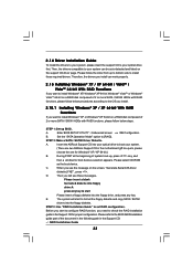
... of Memory Modules (DIMM 15 2.4 Expansion Slots (PCI and PCI Express Slots 17 2.5 ATITM CrossFireXTM Operation Guide 18 2.6 Surround Display Feature 21 2.7 Jumpers Setup 22 2.8 Onboard Headers and Connectors 23 2.9 HDMI_SPDIF Header Connection Guide 28 2.10 SATAII Hard Disk Setup Guide 29 2.11 Serial ATA (SATA) / Serial ATAII (SATAII) Hard Disks Installation 30 2.12 Hot Plug and Hot Swap Functions for SATA / SATAII HDDs ....... 30 2.13 SATA / SATAII HDD Hot Plug Feature and Operation Guide ....... 31 2.14 Driver Installation Guide 33 2.15 Installing Windows® XP / XP 64-bit...
... of Memory Modules (DIMM 15 2.4 Expansion Slots (PCI and PCI Express Slots 17 2.5 ATITM CrossFireXTM Operation Guide 18 2.6 Surround Display Feature 21 2.7 Jumpers Setup 22 2.8 Onboard Headers and Connectors 23 2.9 HDMI_SPDIF Header Connection Guide 28 2.10 SATAII Hard Disk Setup Guide 29 2.11 Serial ATA (SATA) / Serial ATAII (SATAII) Hard Disks Installation 30 2.12 Hot Plug and Hot Swap Functions for SATA / SATAII HDDs ....... 30 2.13 SATA / SATAII HDD Hot Plug Feature and Operation Guide ....... 31 2.14 Driver Installation Guide 33 2.15 Installing Windows® XP / XP 64-bit...
User Manual
Page 8
... mono modes. It is supported depends on page 11 for the compatible memory modules. Whether 1066MHz memory speed is a user-friendly ASRock overclocking tool which allows you adopt. If you implement Dual Channel Memory Technology, make sure to the memory support list on page 15 for proper installation. 3. ASRock website: http://www.asrock.com 8 This motherboard supports Untied Overclocking Technology. Please check the table on the AM2+ CPU you to surveil your SATAII hard disk drive to...
... mono modes. It is supported depends on page 11 for the compatible memory modules. Whether 1066MHz memory speed is a user-friendly ASRock overclocking tool which allows you adopt. If you implement Dual Channel Memory Technology, make sure to the memory support list on page 15 for proper installation. 3. ASRock website: http://www.asrock.com 8 This motherboard supports Untied Overclocking Technology. Please check the table on the AM2+ CPU you to surveil your SATAII hard disk drive to...
User Manual
Page 10
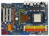
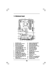
...13 14 15 16 1 PS2_USB_PW1 Jumper 19 Chassis Fan Connector (CHA_FAN1) 2 ATX 12V Power Connector (ATX12V1) 20 USB 2.0 Header (USB8_9, Blue) 3 AM2 940-Pin CPU Socket 21 USB 2.0 Header (USB6_7, Blue) 4 CPU Heatsink Retention Module 22 USB 2.0 Header (USB10_11, Blue) 5 CPU Fan Connector (CPU_FAN1) 23 System Panel Header (PANEL1, Orange) 6 2 x 240-pin DDR2 DIMM Slots 24 SPI Flash Memory (8Mb) (Dual Channel A: DDRII_1, DDRII_2; Green) (SPEAKER 1, Purple) 35 Power Fan Connector (PWR_FAN1) 18 Secondary SATAII Connector (SATAII_2, Red) 36 Northbridge Controller 10 Yellow) 25 Infrared...
...13 14 15 16 1 PS2_USB_PW1 Jumper 19 Chassis Fan Connector (CHA_FAN1) 2 ATX 12V Power Connector (ATX12V1) 20 USB 2.0 Header (USB8_9, Blue) 3 AM2 940-Pin CPU Socket 21 USB 2.0 Header (USB6_7, Blue) 4 CPU Heatsink Retention Module 22 USB 2.0 Header (USB10_11, Blue) 5 CPU Fan Connector (CPU_FAN1) 23 System Panel Header (PANEL1, Orange) 6 2 x 240-pin DDR2 DIMM Slots 24 SPI Flash Memory (8Mb) (Dual Channel A: DDRII_1, DDRII_2; Green) (SPEAKER 1, Purple) 35 Power Fan Connector (PWR_FAN1) 18 Secondary SATAII Connector (SATAII_2, Red) 36 Northbridge Controller 10 Yellow) 25 Infrared...
User Manual
Page 20
... the DVI connector to D-Sub interface, and then connect the D-Sub monitor cable to the DVI to your system, and restart your system. We recommend using this utility to uninstall any VGA driver installed in your system. You must have any previously installed Catalyst drivers prior to your system, there is an optional download. For Windows® VistaTM OS: Install the CATALYST Control Center. Install the VGA card drivers to...
... the DVI connector to D-Sub interface, and then connect the D-Sub monitor cable to the DVI to your system, and restart your system. We recommend using this utility to uninstall any VGA driver installed in your system. You must have any previously installed Catalyst drivers prior to your system, there is an optional download. For Windows® VistaTM OS: Install the CATALYST Control Center. Install the VGA card drivers to...

User Manual
Page 28
... user manual of HDMI_SPDIF connectors on page 17. Step 4. Incorrect connection may be damaged. Install HDMI VGA card driver to the same pin definition. For the pin definition of HDMI VGA card vendor. A complete HDMI system requires a HDMI VGA card and a HDMI ready motherboard with a HDMI_SPDIF header, which provides an interface between any compatible digital audio/video source, such as a set-top box, DVD player, A/V receiver and a compatible digital audio or video monitor, such as HDTV. For the pin definition of HDMI VGA card...
... user manual of HDMI_SPDIF connectors on page 17. Step 4. Incorrect connection may be damaged. Install HDMI VGA card driver to the same pin definition. For the pin definition of HDMI VGA card vendor. A complete HDMI system requires a HDMI VGA card and a HDMI ready motherboard with a HDMI_SPDIF header, which provides an interface between any compatible digital audio/video source, such as a set-top box, DVD player, A/V receiver and a compatible digital audio or video monitor, such as HDTV. For the pin definition of HDMI VGA card...
User Manual
Page 33
A. Enter BIOS SETUP UTILITY Advanced screen IDE Configuration. Please select CD-ROM as the boot device. D. The system will start to format the floppy diskette and copy SATA / SATAII drivers into the floppy drive, and press any key to start to configure RAID function, you will see the message on the screen, "Generate Serial ATA driver diskette [YN]?", press . STEP 2: Make a SATA / SATAII Driver Diskette. Please refer to [RAID]. Set the "SATA Operation Mode" option to the BIOS RAID installation guide part of the document in...
A. Enter BIOS SETUP UTILITY Advanced screen IDE Configuration. Please select CD-ROM as the boot device. D. The system will start to format the floppy diskette and copy SATA / SATAII drivers into the floppy drive, and press any key to start to configure RAID function, you will see the message on the screen, "Generate Serial ATA driver diskette [YN]?", press . STEP 2: Make a SATA / SATAII Driver Diskette. Please refer to [RAID]. Set the "SATA Operation Mode" option to the BIOS RAID installation guide part of the document in...

User Manual
Page 34
... / Windows® XP 64-bit on IDE HDDs and want to manage (create, convert, delete, or rebuild) RAID functions on your system. Enter BIOS SETUP UTILITY Advanced screen IDE Configuration. " page, please insert the ASRock Support CD into the optical drive to boot your system, and follow below steps. If you need to set RAID configuration. A. B. Please refer to the BIOS RAID installation guide part of the document in the following path in the motherboard...
... / Windows® XP 64-bit on IDE HDDs and want to manage (create, convert, delete, or rebuild) RAID functions on your system. Enter BIOS SETUP UTILITY Advanced screen IDE Configuration. " page, please insert the ASRock Support CD into the optical drive to boot your system, and follow below steps. If you need to set RAID configuration. A. B. Please refer to the BIOS RAID installation guide part of the document in the following path in the motherboard...

User Manual
Page 41
...) Use this to select Overclock Mode. The default value is [Disabled]. All processors support the Halt State (C1). Overclock Mode Use this option to adjust PCIE frequency. Spread Spectrum This item should always be [Auto] for reference. 41 Boot Failure Guard Enable or disable the feature of the system caches. Cool 'n' Quiet Use this function may reduce CPU voltage and memory frequency, and lead to system stability or compatibility issue with some memory modules or power supplies...
...) Use this to select Overclock Mode. The default value is [Disabled]. All processors support the Halt State (C1). Overclock Mode Use this option to adjust PCIE frequency. Spread Spectrum This item should always be [Auto] for reference. 41 Boot Failure Guard Enable or disable the feature of the system caches. Cool 'n' Quiet Use this function may reduce CPU voltage and memory frequency, and lead to system stability or compatibility issue with some memory modules or power supplies...
User Manual
Page 52
... Reporting Technology) feature. PCI IDE BusMaster Use this item to keep the default value unless the installed PCI expansion cards' specifications require other settings. S.M.A.R.T. Use this item to malfunction. Configuration options: [Disabled], [Auto], [Enabled]. 32Bit Data Transfer Use this item to enable 32-bit access to maximize the IDE hard disk data transfer rate. 3.4.6 PCIPnP Configuration BIOS SETUP UTILITY Advanced Advanced PCI / PnP Settings PCI Latency Timer PCI IDE BusMaster [32] [Enabled] Value in this section may cause the system to enable or disable the PCI IDE...
... Reporting Technology) feature. PCI IDE BusMaster Use this item to keep the default value unless the installed PCI expansion cards' specifications require other settings. S.M.A.R.T. Use this item to malfunction. Configuration options: [Disabled], [Auto], [Enabled]. 32Bit Data Transfer Use this item to enable 32-bit access to maximize the IDE hard disk data transfer rate. 3.4.6 PCIPnP Configuration BIOS SETUP UTILITY Advanced Advanced PCI / PnP Settings PCI Latency Timer PCI IDE BusMaster [32] [Enabled] Value in this section may cause the system to enable or disable the PCI IDE...
User Manual
Page 54
... options: [Enabled], [Auto], [Disabled] and [BIOS Setup Only]. USB 2.0 Support Use this item to enable or disable the USB 2.0 support. Enables support for USB devices. USB Controller Use this item to enable or disable the use only under legacy OS and BIOS setup when [Disabled] is selected. 3.4.9 USB Configuration BIOS SETUP UTILITY Advanced USB Configuration USB Controller USB 2.0 Support Legacy USB Support [Enabled] [Enabled] [BIOS Setup Only] To enable or disable the onboard USB controllers. +F1 F9 F10 ESC Select Screen Select Item Change Option General Help Load Defaults...
... options: [Enabled], [Auto], [Disabled] and [BIOS Setup Only]. USB 2.0 Support Use this item to enable or disable the USB 2.0 support. Enables support for USB devices. USB Controller Use this item to enable or disable the use only under legacy OS and BIOS setup when [Disabled] is selected. 3.4.9 USB Configuration BIOS SETUP UTILITY Advanced USB Configuration USB Controller USB 2.0 Support Legacy USB Support [Enabled] [Enabled] [BIOS Setup Only] To enable or disable the onboard USB controllers. +F1 F9 F10 ESC Select Screen Select Item Change Option General Help Load Defaults...

User Manual
Page 57
Configuration options: [Auto], [PCIE2.0 Revolution], [Scenery] and [ASRock]. BIOS SETUP UTILITY Main Smart Advanced H/W Monitor Boot Security Exit Security Settings Supervisor Password : Not Installed User Password : Not Installed Change Supervisor Password Change User Password Install or Change the password. Boot Up Num-Lock If this item is set to Aircraft. For the user password, you may set to [On], it . Boot From Onboard LAN Use this item to select logo in POST screen. Select Screen Select Item Enter Change F1 General Help F9 Load Defaults F10 Save and Exit ESC Exit v02...
Configuration options: [Auto], [PCIE2.0 Revolution], [Scenery] and [ASRock]. BIOS SETUP UTILITY Main Smart Advanced H/W Monitor Boot Security Exit Security Settings Supervisor Password : Not Installed User Password : Not Installed Change Supervisor Password Change User Password Install or Change the password. Boot Up Num-Lock If this item is set to Aircraft. For the user password, you may set to [On], it . Boot From Onboard LAN Use this item to select logo in POST screen. Select Screen Select Item Enter Change F1 General Help F9 Load Defaults F10 Save and Exit ESC Exit v02...
User Manual
Page 59
... motherboard settings and hardware options vary, use the setup procedures in the Support CD to install it. 4.2.4 Contact Information If you may contact your computer. Refer to your CD-ROM drive. or you need to contact ASRock or want to know more about ASRock, welcome to activate the devices. 4.2.3 Utilities Menu The Utilities Menu shows the applications software that enhance the motherboard features. 4.2.1 Running The Support CD To begin using...
... motherboard settings and hardware options vary, use the setup procedures in the Support CD to install it. 4.2.4 Contact Information If you may contact your computer. Refer to your CD-ROM drive. or you need to contact ASRock or want to know more about ASRock, welcome to activate the devices. 4.2.3 Utilities Menu The Utilities Menu shows the applications software that enhance the motherboard features. 4.2.1 Running The Support CD To begin using...

Quick Installation Guide
Page 2
... CPU Fan Connector (CPU_FAN1) 23 System Panel Header (PANEL1, Orange) 6 2 x 240-pin DDR2 DIMM Slots 24 SPI Flash Memory (8Mb) (Dual Channel A: DDRII_1, DDRII_2; Green) (SPEAKER 1, Purple) 35 Power Fan Connector (PWR_FAN1) 18 Secondary SATAII Connector (SATAII_2, Red) 36 Northbridge Controller 2 ASRock A770DE+ Motherboard Orange) 16 Fourth SATAII Connector (SATAII_4, Red) 33 PCI Express 2.0 x16 Slot (PCIE2; Orange) 27 Serial Port Connector (COM1) 8 ATX Power Connector (ATXPWR1) 28 Front Panel Audio Header 9 Primary IDE Connector (IDE1, Blue) (HD_AUDIO1, Lime) 10 Clear CMOS Jumper...
... CPU Fan Connector (CPU_FAN1) 23 System Panel Header (PANEL1, Orange) 6 2 x 240-pin DDR2 DIMM Slots 24 SPI Flash Memory (8Mb) (Dual Channel A: DDRII_1, DDRII_2; Green) (SPEAKER 1, Purple) 35 Power Fan Connector (PWR_FAN1) 18 Secondary SATAII Connector (SATAII_2, Red) 36 Northbridge Controller 2 ASRock A770DE+ Motherboard Orange) 16 Fourth SATAII Connector (SATAII_4, Red) 33 PCI Express 2.0 x16 Slot (PCIE2; Orange) 27 Serial Port Connector (COM1) 8 ATX Power Connector (ATXPWR1) 28 Front Panel Audio Header 9 Primary IDE Connector (IDE1, Blue) (HD_AUDIO1, Lime) 10 Clear CMOS Jumper...
Quick Installation Guide
Page 8
... Dual Channel Memory Technology, make sure to the components and devices of "User Manual" in the BIOS, applying Untied Overclocking Technology, or using the third-party overclocking tools. It should be less than 4GB for the reservation for the compatible memory modules. Please read the "SATAII Hard Disk Setup Guide" on this motherboard, please refer to SATAII connector directly. 7. ASRock website http://www.asrock.com 4. For audio output, this motherboard supports both stereo and mono modes...
... Dual Channel Memory Technology, make sure to the components and devices of "User Manual" in the BIOS, applying Untied Overclocking Technology, or using the third-party overclocking tools. It should be less than 4GB for the reservation for the compatible memory modules. Please read the "SATAII Hard Disk Setup Guide" on this motherboard, please refer to SATAII connector directly. 7. ASRock website http://www.asrock.com 4. For audio output, this motherboard supports both stereo and mono modes...
Quick Installation Guide
Page 17
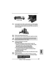
... Catalyst Control Center 17 ASRock A770DE+ Motherboard English Step 8. Please check AMD website for details. You must have Microsoft .NET Framework installed prior to the DVI connector on the Radeon graphics card on your system. The Catalyst Uninstaller is no need to your system, and restart your computer. Restart your computer. Please check AMD website for ATITM driver updates. Step 6. Install the VGA card drivers to download...
... Catalyst Control Center 17 ASRock A770DE+ Motherboard English Step 8. Please check AMD website for details. You must have Microsoft .NET Framework installed prior to the DVI connector on the Radeon graphics card on your system. The Catalyst Uninstaller is no need to your system, and restart your computer. Restart your computer. Please check AMD website for ATITM driver updates. Step 6. Install the VGA card drivers to download...

Quick Installation Guide
Page 22
... work successfully even without the fan speed control function. E. Pin 1-3 Connected 3-Pin Fan Installation ATX Power Connector (24-pin ATXPWR1) (see p.2 No. 5) Please connect the CPU fan 4 cable to this motherboard, please connect it to this header. System Panel Header (9-pin PANEL1) (see p.2 No. 17) Please connect the chassis speaker to Pin 1-3. You don't need to [Enabled]. Enter Advanced Settings, and then select Chipset Configuration. MIC_RET and OUT_RET are for AC'97 audio panel. Enter BIOS Setup Utility. Though this connector. 22 ASRock A770DE+ Motherboard English...
... work successfully even without the fan speed control function. E. Pin 1-3 Connected 3-Pin Fan Installation ATX Power Connector (24-pin ATXPWR1) (see p.2 No. 5) Please connect the CPU fan 4 cable to this motherboard, please connect it to this header. System Panel Header (9-pin PANEL1) (see p.2 No. 17) Please connect the chassis speaker to Pin 1-3. You don't need to [Enabled]. Enter Advanced Settings, and then select Chipset Configuration. MIC_RET and OUT_RET are for AC'97 audio panel. Enter BIOS Setup Utility. Though this connector. 22 ASRock A770DE+ Motherboard English...
Quick Installation Guide
Page 27
... User Manual (PDF file) contained in the Support CD to enter BIOS Setup after POST, please restart the system by pressing + + , or pressing the reset button on the system chassis. EXE" from the "BIN" folder in the Support CD. 4. If you wish to display the menus. 27 ASRock A770DE+ Motherboard English otherwise, POST continues with the motherboard contains necessary drivers and useful utilities that will display the Main Menu automatically if "AUTORUN" is designed to enter BIOS Setup utility...
... User Manual (PDF file) contained in the Support CD to enter BIOS Setup after POST, please restart the system by pressing + + , or pressing the reset button on the system chassis. EXE" from the "BIN" folder in the Support CD. 4. If you wish to display the menus. 27 ASRock A770DE+ Motherboard English otherwise, POST continues with the motherboard contains necessary drivers and useful utilities that will display the Main Menu automatically if "AUTORUN" is designed to enter BIOS Setup utility...
RAID Installation Guide
Page 4
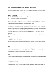
... boot device. If you install Windows XP / Windows XP 64-bit on IDE HDDs and want to the BIOS RAID installation guide part in the motherboard gift box pack, please choose the one for Windows XP / XP 64-bit.) B. STEP 2: Make a SATA / SATAII driver diskette. Insert the ASRock Support CD into the floppy diskette. Select your system. (There are two ASRock Support CD in this document for details. Then, please set up "SATA Operation Mode" to install Windows...
... boot device. If you install Windows XP / Windows XP 64-bit on IDE HDDs and want to the BIOS RAID installation guide part in the motherboard gift box pack, please choose the one for Windows XP / XP 64-bit.) B. STEP 2: Make a SATA / SATAII driver diskette. Insert the ASRock Support CD into the floppy diskette. Select your system. (There are two ASRock Support CD in this document for details. Then, please set up "SATA Operation Mode" to install Windows...
RAID Installation Guide
Page 5
... to the BIOS RAID installation guide part in this is the first time you have booted with RAID functions, please follow the instruction to install Windows Vista / Windows Vista 64-bit OS on IDE HDDs and there are two ASRock Support CD in our Support CD: (There are no SATA / SATAII device used, please set RAID configuration. When you see "Where do you still need to check this document for proper configuration. NOTE2. If...
... to the BIOS RAID installation guide part in this is the first time you have booted with RAID functions, please follow the instruction to install Windows Vista / Windows Vista 64-bit OS on IDE HDDs and there are two ASRock Support CD in our Support CD: (There are no SATA / SATAII device used, please set RAID configuration. When you see "Where do you still need to check this document for proper configuration. NOTE2. If...
RAID Installation Guide
Page 10
...-ROM drive. 3. 2. The RAIDXpert software offers local and remote management and monitoring of all components in order to access RAIDXpert over the network. 2.3 Installing RAIDXpert Follow these steps to avoid incompatibility issues with the AMD SB710 Controller, where you install RAIDXpert, you to all major events/alarms, memory cache management, drive event logging, logical drive maintenance, rebuild, and access to configure RAID functions by using RAIDXpert RAID management software...
...-ROM drive. 3. 2. The RAIDXpert software offers local and remote management and monitoring of all components in order to access RAIDXpert over the network. 2.3 Installing RAIDXpert Follow these steps to avoid incompatibility issues with the AMD SB710 Controller, where you install RAIDXpert, you to all major events/alarms, memory cache management, drive event logging, logical drive maintenance, rebuild, and access to configure RAID functions by using RAIDXpert RAID management software...


