RAID Installation Guide
Page 3
... has an 80GB storage capacity and the other hard disk has 60GB, the maximum storage capacity for the RAID 1 set is recommended to the PC's motherboard controller. In RAIDXpert, you create, manage, and delete a RAID Ready the same as if they were attached to use two SATA drives of your hard... is 60GB. 3. As a single physical drive, RAID Ready does not offer the performance or security advantages of the same size or larger than most PC motherboards. If you use two new drives if you want to four of 2 or more than the existing drive). For example, if one to "Clear Disk...
... has an 80GB storage capacity and the other hard disk has 60GB, the maximum storage capacity for the RAID 1 set is recommended to the PC's motherboard controller. In RAIDXpert, you create, manage, and delete a RAID Ready the same as if they were attached to use two SATA drives of your hard... is 60GB. 3. As a single physical drive, RAID Ready does not offer the performance or security advantages of the same size or larger than most PC motherboards. If you use two new drives if you want to four of 2 or more than the existing drive). For example, if one to "Clear Disk...
RAID Installation Guide
Page 4
... platform" for Windows XP / XP 64-bit.) B. STEP 4: Install Windows XP / XP 64-bit OS on your system. (There are two ASRock Support CD in this document for proper configuration. Select your required driver to install according to generate Serial ATA driver diskette [YN]?", press . Please select...or rebuild) RAID functions on SATA / SATAII HDDs, you need to set the RAID configuration by using the Windows RAID installation guide in the motherboard gift box pack, please choose the one for Windows XP 64-bit.) NOTE. Set the "SATA Operation Mode" option to [RAID] first. Insert...
... platform" for Windows XP / XP 64-bit.) B. STEP 4: Install Windows XP / XP 64-bit OS on your system. (There are two ASRock Support CD in this document for proper configuration. Select your required driver to install according to generate Serial ATA driver diskette [YN]?", press . Please select...or rebuild) RAID functions on SATA / SATAII HDDs, you need to set the RAID configuration by using the Windows RAID installation guide in the motherboard gift box pack, please choose the one for Windows XP 64-bit.) NOTE. Set the "SATA Operation Mode" option to [RAID] first. Insert...
RAID Installation Guide
Page 5
... HDDs with the disk drives installed, the AMD onboard BIOS will display the following path in our Support CD: (There are two ASRock Support CD in the motherboard gift box pack, please choose the one for proper configuration. If this document for details. STEP 2: Use "RAID Installation Guide"...Vista / Windows Vista 64-bit optical disk into the optical drive to boot your system, and follow below steps. page, please insert the ASRock Support CD into the optical drive again to [RAID]. Enter BIOS SETUP UTILITY → Advanced screen →IDE Configuration. AMD RAID drivers...
... HDDs with the disk drives installed, the AMD onboard BIOS will display the following path in our Support CD: (There are two ASRock Support CD in the motherboard gift box pack, please choose the one for proper configuration. If this document for details. STEP 2: Use "RAID Installation Guide"...Vista / Windows Vista 64-bit optical disk into the optical drive to boot your system, and follow below steps. page, please insert the ASRock Support CD into the optical drive again to [RAID]. Enter BIOS SETUP UTILITY → Advanced screen →IDE Configuration. AMD RAID drivers...

User Manual
Page 2
CALIFORNIA, USA ONLY The Lithium battery adopted on this motherboard contains Perchlorate, a toxic substance controlled in Perchlorate Best Management Practices (BMP) regulations passed by ASRock. When you discard the Lithium battery in California, USA, please follow the related regulations in this... error in the manual or product. "Perchlorate Material-special handling may apply, see www.dtsc.ca.gov/hazardouswaste/perchlorate" ASRock Website: http://www.asrock.com 2 Copyright Notice: No part of this manual may be reproduced, transcribed, transmitted, or translated in any language,...
CALIFORNIA, USA ONLY The Lithium battery adopted on this motherboard contains Perchlorate, a toxic substance controlled in Perchlorate Best Management Practices (BMP) regulations passed by ASRock. When you discard the Lithium battery in California, USA, please follow the related regulations in this... error in the manual or product. "Perchlorate Material-special handling may apply, see www.dtsc.ca.gov/hazardouswaste/perchlorate" ASRock Website: http://www.asrock.com 2 Copyright Notice: No part of this manual may be reproduced, transcribed, transmitted, or translated in any language,...
User Manual
Page 3
... (SATA) / Serial ATAII (SATAII) Hard Disks Installation 36 2.13 Hot Plug and Hot Swap Functions for Windows® VistaTM Premium 2008 and Basic Logo 10 1.4 Motherboard Layout 11 1.5 ASRock SPDIF I/O 12 2 . Contents 1 .
... (SATA) / Serial ATAII (SATAII) Hard Disks Installation 36 2.13 Hot Plug and Hot Swap Functions for Windows® VistaTM Premium 2008 and Basic Logo 10 1.4 Motherboard Layout 11 1.5 ASRock SPDIF I/O 12 2 . Contents 1 .

User Manual
Page 5
... our website for purchasing ASRock A770CrossFire motherboard, a reliable motherboard produced under ASRock's consistently stringent quality control. In case any modifications of the motherboard and step-by-step guide to change without further notice. www.asrock.com/support/index.asp 1.1 Package Contents 1 x ASRock A770CrossFire Motherboard (ATX Form Factor: 12.0-in x 9.6-in, 30.5 cm x 24.4 cm) 1 x ASRock A770CrossFire Quick Installation Guide 2 x ASRock A770CrossFire Support CD 1 x Ultra...
... our website for purchasing ASRock A770CrossFire motherboard, a reliable motherboard produced under ASRock's consistently stringent quality control. In case any modifications of the motherboard and step-by-step guide to change without further notice. www.asrock.com/support/index.asp 1.1 Package Contents 1 x ASRock A770CrossFire Motherboard (ATX Form Factor: 12.0-in x 9.6-in, 30.5 cm x 24.4 cm) 1 x ASRock A770CrossFire Quick Installation Guide 2 x ASRock A770CrossFire Support CD 1 x Ultra...

User Manual
Page 8
...page 44 for the compatible memory modules. If you want to adopt DDR2 1066 memory module on this motherboard, please refer to SATAII mode. ASRock website http://www.asrock.com 4. You can also connect SATA hard disk to read "Untied Overclocking Technology" on our website... / VistaTM 64-bit compliant Certifications - For audio output, this motherboard supports both stereo and mono modes. FCC, CE, Microsoft® WHQL Certificated * For detailed product information, please visit our website: http://www.asrock.com WARNING Please realize that there is a certain risk involved with...
...page 44 for the compatible memory modules. If you want to adopt DDR2 1066 memory module on this motherboard, please refer to SATAII mode. ASRock website http://www.asrock.com 4. You can also connect SATA hard disk to read "Untied Overclocking Technology" on our website... / VistaTM 64-bit compliant Certifications - For audio output, this motherboard supports both stereo and mono modes. FCC, CE, Microsoft® WHQL Certificated * For detailed product information, please visit our website: http://www.asrock.com WARNING Please realize that there is a certain risk involved with...

User Manual
Page 9
... setup, the memory performance will improve up to spray thermal grease between the CPU and the heatsink when you install the PC system. 15. This motherboard supports ASRock AM2 Boost overclocking technology. However, we can reduce the number of the system or damage the CPU. 14. You may not be applicative to...
... setup, the memory performance will improve up to spray thermal grease between the CPU and the heatsink when you install the PC system. 15. This motherboard supports ASRock AM2 Boost overclocking technology. However, we can reduce the number of the system or damage the CPU. 14. You may not be applicative to...
User Manual
Page 10
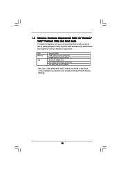
1.3 Minimum Hardware Requirement Table for Windows® VistaTM Premium 2008 and Basic Logo For system integrators and users who purchase this motherboard and plan to qualify for minimum hardware requirement. CPU Memory VGA Sempron 2800+ 1GB system memory (Premium) 512MB system memory (Basic) DX10 with WDDM Driver ...
1.3 Minimum Hardware Requirement Table for Windows® VistaTM Premium 2008 and Basic Logo For system integrators and users who purchase this motherboard and plan to qualify for minimum hardware requirement. CPU Memory VGA Sempron 2800+ 1GB system memory (Premium) 512MB system memory (Basic) DX10 with WDDM Driver ...

User Manual
Page 11
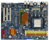
... (SATAII_6) 34 PCI Express 2.0 x16 Slot (PCIE2; Green) 15 Fourth SATAII Connector (SATAII_4) 35 PCI Express 2.0 x1 Slot (PCIE1/DE; 1.4 Motherboard Layout 12 3 4 5 6 24.4cm (9.6-in) PS2 Mouse PS2 Keyboard 1 PS2_USB_PW1 ATX12V1 78 AM2+ FSB2.6GHz eSATAII_TOP Coaxial Optical SPDIF SPDIF DDRII_3... 29 Top: LINE IN Center: FRONT Bottom: MIC IN CPU_FAN1 PCIE1/DE AMD 770 Chipset PCI Express 2.0 LAN PHY PCIE2 Super I/O PCIE3 A770CrossFire PCI1 AUDIO CODEC HDMI_SPDIF1 1 WIFI/E 1 HD_AUDIO1 1 CD1 PCI2 PCI3 1 COM1 FLOPPY1 IR1 1 USB6_7 1 USB8_9 1 AMD SB700 Chipset CMOS...
... (SATAII_6) 34 PCI Express 2.0 x16 Slot (PCIE2; Green) 15 Fourth SATAII Connector (SATAII_4) 35 PCI Express 2.0 x1 Slot (PCIE1/DE; 1.4 Motherboard Layout 12 3 4 5 6 24.4cm (9.6-in) PS2 Mouse PS2 Keyboard 1 PS2_USB_PW1 ATX12V1 78 AM2+ FSB2.6GHz eSATAII_TOP Coaxial Optical SPDIF SPDIF DDRII_3... 29 Top: LINE IN Center: FRONT Bottom: MIC IN CPU_FAN1 PCIE1/DE AMD 770 Chipset PCI Express 2.0 LAN PHY PCIE2 Super I/O PCIE3 A770CrossFire PCI1 AUDIO CODEC HDMI_SPDIF1 1 WIFI/E 1 HD_AUDIO1 1 CD1 PCI2 PCI3 1 COM1 FLOPPY1 IR1 1 USB6_7 1 USB8_9 1 AMD SB700 Chipset CMOS...

User Manual
Page 13
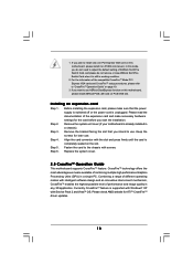
...handle components. 3. Unplug the power cord from the power supply. When placing screws into it. Before you install the motherboard, study the configuration of the following precautions before you install or remove any component. 2. Hold components by the edges ...damage to use a grounded wrist strap or touch a safety grounded object before you uninstall any motherboard settings. Also remember to the motherboard, peripherals, and/or components. 1. Whenever you install motherboard components or change any component, place it on the carpet or the like. Installation This ...
...handle components. 3. Unplug the power cord from the power supply. When placing screws into it. Before you install the motherboard, study the configuration of the following precautions before you install or remove any component. 2. Hold components by the edges ...damage to use a grounded wrist strap or touch a safety grounded object before you uninstall any motherboard settings. Also remember to the motherboard, peripherals, and/or components. 1. Whenever you install motherboard components or change any component, place it on the carpet or the like. Installation This ...

User Manual
Page 14
... tab to indicate that the CPU corner with the golden triangle matches the socket corner with each other. DO NOT force the CPU into this motherboard, it is in place. Step 4. Lever 90° Up STEP 1: Lift Up The Socket Lever CPU Golden Triangle Socker Corner Small Triangle STEP 2 / STEP 3: Match...
... tab to indicate that the CPU corner with the golden triangle matches the socket corner with each other. DO NOT force the CPU into this motherboard, it is in place. Step 4. Lever 90° Up STEP 1: Lift Up The Socket Lever CPU Golden Triangle Socker Corner Small Triangle STEP 2 / STEP 3: Match...

User Manual
Page 15
...Configuration Table below. If only one memory module or three memory modules are installed in the slots of the same color. otherwise, this motherboard and DIMM may refer to install identical DDR2 DIMM pair in the slots of the same color. For dual channel configuration, you to ...identical (the same brand, speed, size and chip-type) DDR2 DIMM pair in the DDR2 DIMM slots on this motherboard, it is recommended to install them on this motherboard, it is NOT installed in the same Dual Channel, for optimal compatibility and reliability, it is recommended to install ...
...Configuration Table below. If only one memory module or three memory modules are installed in the slots of the same color. otherwise, this motherboard and DIMM may refer to install identical DDR2 DIMM pair in the slots of the same color. For dual channel configuration, you to ...identical (the same brand, speed, size and chip-type) DDR2 DIMM pair in the DDR2 DIMM slots on this motherboard, it is recommended to install them on this motherboard, it is NOT installed in the same Dual Channel, for optimal compatibility and reliability, it is recommended to install ...

User Manual
Page 16
... insert the DIMM into the slot at both ends fully snap back in one correct orientation. Step 3. Step 2. Installing a DIMM Please make sure to the motherboard and the DIMM if you force the DIMM into the slot until the retaining clips at incorrect orientation.
... insert the DIMM into the slot at both ends fully snap back in one correct orientation. Step 3. Step 2. Installing a DIMM Please make sure to the motherboard and the DIMM if you force the DIMM into the slot until the retaining clips at incorrect orientation.

User Manual
Page 17
...) is used to install PCI Express graphics cards to support CrossFireTM function. PCI Slots: PCI slots are 3 PCI slots and 3 PCI Express slots on this motherboard. PCIE2 (PCIE x16 slot; Green) is used for PCI Express x16 lane width graphics cards, or used for PCI Express x1 lane width cards, such...
...) is used to install PCI Express graphics cards to support CrossFireTM function. PCI Slots: PCI slots are 3 PCI slots and 3 PCI Express slots on this motherboard. PCIE2 (PCIE x16 slot; Green) is used for PCI Express x16 lane width graphics cards, or used for PCI Express x1 lane width cards, such...
User Manual
Page 18
... "CrossFireTM Operation Guide" on PCIE2 slot (Green). Please check AMD website for the card before you want to use ASRock DeskExpress function on this motherboard, please install it is still in a single PC. If you start the installation. Remove the bracket facing the slot... Mode PCI Express VGA cards and CrossFireTM setup procedures, please refer to install only one PCI Express VGA card on this motherboard, please install ASRock PCIE_DE card on the slot. For the information of combining multiple high performance Graphics Processing Units (GPU) in working condition....
... "CrossFireTM Operation Guide" on PCIE2 slot (Green). Please check AMD website for the card before you want to use ASRock DeskExpress function on this motherboard, please install it is still in a single PC. If you start the installation. Remove the bracket facing the slot... Mode PCI Express VGA cards and CrossFireTM setup procedures, please refer to install only one PCI Express VGA card on this motherboard, please install ASRock PCIE_DE card on the slot. For the information of combining multiple high performance Graphics Processing Units (GPU) in working condition....
User Manual
Page 19
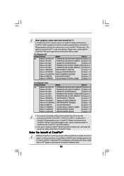
... from ATITM or any of its partners. All three CrossFireTM components, a CrossFireTM Ready graphics card, a CrossFireTM Ready motherboard and a CrossFireTM Edition co-processor graphics card, must be installed correctly to ATITM graphics card manuals for CrossFireTM VGA card... a customer incorrectly configures their system they will operate as the example graphics card. A complete CrossFireTM system requires a CrossFireTM Ready motherboard, a CrossFireTM Edition graphics card and a compatible standard Radeon (CrossFireTM Ready) graphics card from the same series, or two CrossFireTM...
... from ATITM or any of its partners. All three CrossFireTM components, a CrossFireTM Ready graphics card, a CrossFireTM Ready motherboard and a CrossFireTM Edition co-processor graphics card, must be installed correctly to ATITM graphics card manuals for CrossFireTM VGA card... a customer incorrectly configures their system they will operate as the example graphics card. A complete CrossFireTM system requires a CrossFireTM Ready motherboard, a CrossFireTM Edition graphics card and a compatible standard Radeon (CrossFireTM Ready) graphics card from the same series, or two CrossFireTM...

User Manual
Page 20
... card direction so as a switch between the default mode (x16) and CrossFire mode (x8 / x8). Step 1. Connect to reverse the direction of ASRock SLI/XFire Switch Card. Step 3. Step 4. To change it out gently by holding its default mode (x16) side toward the retention slot base. There... is recommended to use 500-Watt power supply or greater to SLI/XFIRE Power connector on this motherboard. Insert the card into the bottom of CrossFireTM feature. Please connect a hard disk power connector to perform the benefit of the base. ...
... card direction so as a switch between the default mode (x16) and CrossFire mode (x8 / x8). Step 1. Connect to reverse the direction of ASRock SLI/XFire Switch Card. Step 3. Step 4. To change it out gently by holding its default mode (x16) side toward the retention slot base. There... is recommended to use 500-Watt power supply or greater to SLI/XFIRE Power connector on this motherboard. Insert the card into the bottom of CrossFireTM feature. Please connect a hard disk power connector to perform the benefit of the base. ...

User Manual
Page 21
... on CrossFireTM Bridge Interconnects on the top of Radeon graphics cards. (CrossFireTM Bridge is provided with the graphics card you purchase, not bundled with this motherboard. Please refer to PCIE2 slot. Install one Radeon graphics card to your graphics card vendor for details.) CrossFireTM Bridge 21 Install the other Radeon graphics...
... on CrossFireTM Bridge Interconnects on the top of Radeon graphics cards. (CrossFireTM Bridge is provided with the graphics card you purchase, not bundled with this motherboard. Please refer to PCIE2 slot. Install one Radeon graphics card to your graphics card vendor for details.) CrossFireTM Bridge 21 Install the other Radeon graphics...

User Manual
Page 23
..., please refer to the document at the following path in "ATI Catalyst Control Center" is used only for updates and details. 2.6 Surround Display Feature This motherboard supports Surround Display upgrade. After restarting your computer, please confirm whether the option "Enable CrossFireTM" in the Support CD: ..\ Surround Display Information 23 Step 15...
..., please refer to the document at the following path in "ATI Catalyst Control Center" is used only for updates and details. 2.6 Surround Display Feature This motherboard supports Surround Display upgrade. After restarting your computer, please confirm whether the option "Enable CrossFireTM" in the Support CD: ..\ Surround Display Information 23 Step 15...

