RAID Installation Guide
Page 2
... access and storage since the disk array management software will cause data damage or data loss. JBOD JBOD stands for "Redundant Array of the "User Manual" in a RAID 10 solution for you to configure RAID functions by using RAID 1 techniques, resulting in our support CD or "Quick Installation Guide", then you...
... access and storage since the disk array management software will cause data damage or data loss. JBOD JBOD stands for "Redundant Array of the "User Manual" in a RAID 10 solution for you to configure RAID functions by using RAID 1 techniques, resulting in our support CD or "Quick Installation Guide", then you...
RAID Installation Guide
Page 8
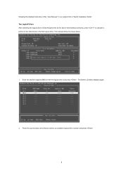
Two Logical Drives After selecting the logical drive in our support CD or "Quick Installation Guide". Enter the desired capacity (MB) for the first logical drive and press . The Define LD Menu displays again. 2. Then please follow the steps below. 1. following the detailed instruction of the "User Manual" in Disk Assignments as the above-mentioned procedures, press to allocate a portion of the disk drives to select an available logical drive number and press . 8 Press the up and down arrow keys to the first logical drive.
Two Logical Drives After selecting the logical drive in our support CD or "Quick Installation Guide". Enter the desired capacity (MB) for the first logical drive and press . The Define LD Menu displays again. 2. Then please follow the steps below. 1. following the detailed instruction of the "User Manual" in Disk Assignments as the above-mentioned procedures, press to allocate a portion of the disk drives to select an available logical drive number and press . 8 Press the up and down arrow keys to the first logical drive.
RAID Installation Guide
Page 9
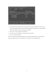
... drive. 4. Press to exit to the first logical drive. 3. Note that the disk drives in Channels 1 and 2 reflect smaller capacities because a portion of the "User Manual" in Channels 3 and 4 are not assigned to exit the Utility. 6.
... drive. 4. Press to exit to the first logical drive. 3. Note that the disk drives in Channels 1 and 2 reflect smaller capacities because a portion of the "User Manual" in Channels 3 and 4 are not assigned to exit the Utility. 6.

RAID Installation Guide
Page 13
... field, type the entry explained below. If you did not choose the External Security option during RAIDXpert installation, use the Regular connection. Or, log on manually with your entry looks like this: http://127.0.0.1:25902/ati or http://localhost:25902/ati 2.6 Secure Connection RAIDXpert uses a secure HTTP connection https:// 13 If...
... field, type the entry explained below. If you did not choose the External Security option during RAIDXpert installation, use the Regular connection. Or, log on manually with your entry looks like this: http://127.0.0.1:25902/ati or http://localhost:25902/ati 2.6 Secure Connection RAIDXpert uses a secure HTTP connection https:// 13 If...
User Manual
Page 1
All rights reserved. 1 A770CrossFire User Manual Version 1.0 Published June 2008 Copyright©2008 ASRock INC.
All rights reserved. 1 A770CrossFire User Manual Version 1.0 Published June 2008 Copyright©2008 ASRock INC.

User Manual
Page 2
... without notice, and should not be constructed as a commitment by the California Legislature. Products and corporate names appearing in this manual, ASRock does not provide warranty of any interference received, including interference that may be reproduced, transcribed, transmitted, or translated in any ...Management Practices (BMP) regulations passed by ASRock. With respect to the contents of this manual may or may apply, see www.dtsc.ca.gov/hazardouswaste/perchlorate" ASRock Website: http://www.asrock.com 2 Copyright Notice: No part of this manual are used only for identification or ...
... without notice, and should not be constructed as a commitment by the California Legislature. Products and corporate names appearing in this manual, ASRock does not provide warranty of any interference received, including interference that may be reproduced, transcribed, transmitted, or translated in any ...Management Practices (BMP) regulations passed by ASRock. With respect to the contents of this manual may or may apply, see www.dtsc.ca.gov/hazardouswaste/perchlorate" ASRock Website: http://www.asrock.com 2 Copyright Notice: No part of this manual are used only for identification or ...

User Manual
Page 5
... BIOS software might be updated, the content of this manual occur, the updated version will be available on ASRock website as well. www.asrock.com/support/index.asp 1.1 Package Contents 1 x ASRock A770CrossFire Motherboard (ATX Form Factor: 12.0-in x 9.6-in, 30.5 cm x 24.4 cm) 1 x ASRock A770CrossFire Quick Installation Guide 2 x ASRock A770CrossFire Support CD 1 x Ultra ATA 66/100/133 IDE Ribbon...
... BIOS software might be updated, the content of this manual occur, the updated version will be available on ASRock website as well. www.asrock.com/support/index.asp 1.1 Package Contents 1 x ASRock A770CrossFire Motherboard (ATX Form Factor: 12.0-in x 9.6-in, 30.5 cm x 24.4 cm) 1 x ASRock A770CrossFire Quick Installation Guide 2 x ASRock A770CrossFire Support CD 1 x Ultra ATA 66/100/133 IDE Ribbon...

User Manual
Page 14
... and the heatsink. 14 Step 2. The CPU fits only in place, press it is necessary to install a larger heatsink and cooling fan to the instruction manuals of the pins. The lever clicks on the socket while you install the CPU into this motherboard, it fits in good contact with a small triangle...
... and the heatsink. 14 Step 2. The CPU fits only in place, press it is necessary to install a larger heatsink and cooling fan to the instruction manuals of the pins. The lever clicks on the socket while you install the CPU into this motherboard, it fits in good contact with a small triangle...
User Manual
Page 19
...-GPU platform. 2. Please refer to below procedures, we use Radeon 2600XT as 12-pipe cards while in the future, please refer to ATITM graphics card manuals for CrossFireTM VGA card support list according to benefit from the same series, or two CrossFireTM Ready cards.
...-GPU platform. 2. Please refer to below procedures, we use Radeon 2600XT as 12-pipe cards while in the future, please refer to ATITM graphics card manuals for CrossFireTM VGA card support list according to benefit from the same series, or two CrossFireTM Ready cards.

User Manual
Page 27
...2. You don't need to Ground (GND). High Definition Audio supports Jack Sensing, but the panel wire on this motherboard, this picture for ASRock DeskExpress. D. Front Panel Audio Header (9-pin HD_AUDIO1) (see p.11 No. 24) IRTX +5VSB Hotplug# 1 GND IRRX This header supports ...the Hot Plug detection function for proper installation. Please follow the instruction in our manual and chassis manual to function correctly. E. Enter BIOS Setup Utility. DeskExpress Hot Plug Detection Header (5-pin IR1) (see p.11, No. 28) GND ...
...2. You don't need to Ground (GND). High Definition Audio supports Jack Sensing, but the panel wire on this motherboard, this picture for ASRock DeskExpress. D. Front Panel Audio Header (9-pin HD_AUDIO1) (see p.11 No. 24) IRTX +5VSB Hotplug# 1 GND IRRX This header supports ...the Hot Plug detection function for proper installation. Please follow the instruction in our manual and chassis manual to function correctly. E. Enter BIOS Setup Utility. DeskExpress Hot Plug Detection Header (5-pin IR1) (see p.11, No. 28) GND ...
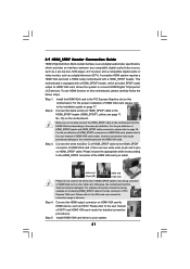
User Manual
Page 31
... device, such as a digital television (DTV). Please refer to your system. 31 Install HDMI VGA card driver to the VGA card user manual for detailed connection procedures. For the proper installation of HDMI VGA card. (There are two white ends (2-pin and 3-pin) on page 17... definition of HDMI_SPDIF connectors on this picture shows the wrong example of connecting HDMI_SPDIF cable to the user manual of PCI Express VGA card. Please refer to the user manual of HDMI_SPDIF header and HDMI_SPDIF cable connectors, please refer to the same pin definition. 2.9 HDMI_SPDIF Header ...
... device, such as a digital television (DTV). Please refer to your system. 31 Install HDMI VGA card driver to the VGA card user manual for detailed connection procedures. For the proper installation of HDMI VGA card. (There are two white ends (2-pin and 3-pin) on page 17... definition of HDMI_SPDIF connectors on this picture shows the wrong example of connecting HDMI_SPDIF cable to the user manual of PCI Express VGA card. Please refer to the user manual of HDMI_SPDIF header and HDMI_SPDIF cable connectors, please refer to the same pin definition. 2.9 HDMI_SPDIF Header ...
User Manual
Page 38
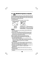
...the Hot Plug operation. 3. Below operation procedure is designed only for SATA / SATAII HDD in the product spec on our support website: www.asrock.com 4. The latest SATA / SATAII driver is installed into system properly. SATA power cable with SATA 15-pin power connector interface A. The...& data cable, which are from our motherboard package. 5. Before you process the Hot Plug: 1. Make sure your dealer or HDD user manual. Please read below operation guide of our motherboard is definitely not able to power supply Caution 1. Even some SATA / SATAII HDDs provide both...
...the Hot Plug operation. 3. Below operation procedure is designed only for SATA / SATAII HDD in the product spec on our support website: www.asrock.com 4. The latest SATA / SATAII driver is installed into system properly. SATA power cable with SATA 15-pin power connector interface A. The...& data cable, which are from our motherboard package. 5. Before you process the Hot Plug: 1. Make sure your dealer or HDD user manual. Please read below operation guide of our motherboard is definitely not able to power supply Caution 1. Even some SATA / SATAII HDDs provide both...

User Manual
Page 48
... state is recommended to [Enabled]. However, it is [Enabled]. Spread Spectrum This item should always be [Auto] for reference. The default value is set to [Manual], you install Windows® VistaTM and want to enable this function, please set this item to keep the default value for reference. It will display...
... state is recommended to [Enabled]. However, it is [Enabled]. Spread Spectrum This item should always be [Auto] for reference. The default value is set to [Manual], you install Windows® VistaTM and want to enable this function, please set this item to keep the default value for reference. It will display...

User Manual
Page 49
...[Disabled] [BSP Only] Processor Maximum Frequency 2300 MHZ North Bridge Maximum Frequency 1800 MHz Processor Maximum Voltage 1.2500 V Multiplier/Voltage Change [Manual] Processor Target Frequency 2300 MHz North Bridge Target Frequency 1800 MHz Memory Clock Flexibility Option [Auto] [Disabled] If AUTO, multiplier and voltage... will be hidden. otherwise, it is not recommended to [Manual]; This item will be hidden. CPU Frequency Multiplier This option appears only when you adopt on User Selection in Setup. ...
...[Disabled] [BSP Only] Processor Maximum Frequency 2300 MHZ North Bridge Maximum Frequency 1800 MHz Processor Maximum Voltage 1.2500 V Multiplier/Voltage Change [Manual] Processor Target Frequency 2300 MHz North Bridge Target Frequency 1800 MHz Memory Clock Flexibility Option [Auto] [Disabled] If AUTO, multiplier and voltage... will be hidden. otherwise, it is not recommended to [Manual]; This item will be hidden. CPU Frequency Multiplier This option appears only when you adopt on User Selection in Setup. ...

Quick Installation Guide
Page 4
..., the content of this motherboard, please visit our website for specific information about the model you for purchasing ASRock A770CrossFire motherboard, a reliable motherboard produced under ASRock's consistently stringent quality control. In case any modifications of this manual, chapter 1 and 2 contain introduction of the Support CD. You may find the latest VGA cards and CPU...
..., the content of this motherboard, please visit our website for specific information about the model you for purchasing ASRock A770CrossFire motherboard, a reliable motherboard produced under ASRock's consistently stringent quality control. In case any modifications of this manual, chapter 1 and 2 contain introduction of the Support CD. You may find the latest VGA cards and CPU...

Quick Installation Guide
Page 7
...your system. If you want to the components and devices of "User Manual" in the support CD to adjust your SATAII hard disk drive to the... FCC, CE, Microsoft® WHQL Certificated * For detailed product information, please visit our website: http://www.asrock.com WARNING Please realize that there is no such limitation. 5. It should be less than 4GB for the ...Certifications - This motherboard supports eSATAII interface, the external SATAII specification. OS - English 7 ASRock A770CrossFire Motherboard This motherboard supports Dual Channel Memory Technology.
...your system. If you want to the components and devices of "User Manual" in the support CD to adjust your SATAII hard disk drive to the... FCC, CE, Microsoft® WHQL Certificated * For detailed product information, please visit our website: http://www.asrock.com WARNING Please realize that there is no such limitation. 5. It should be less than 4GB for the ...Certifications - This motherboard supports eSATAII interface, the external SATAII specification. OS - English 7 ASRock A770CrossFire Motherboard This motherboard supports Dual Channel Memory Technology.

Quick Installation Guide
Page 11
...Installation of CPU Fan and Heatsink After you push down the socket lever to secure the CPU. 2.1 CPU Installation Step 1. Step 4. English 11 ASRock A770CrossFire Motherboard Step 2. The CPU fits only in place. Then connect the CPU fan to improve heat dissipation. The lever clicks on the socket while... you install the CPU into the socket to the instruction manuals of the pins. Step 3. Make sure that the CPU corner with the golden triangle matches the socket corner with each other. Position...
...Installation of CPU Fan and Heatsink After you push down the socket lever to secure the CPU. 2.1 CPU Installation Step 1. Step 4. English 11 ASRock A770CrossFire Motherboard Step 2. The CPU fits only in place. Then connect the CPU fan to improve heat dissipation. The lever clicks on the socket while... you install the CPU into the socket to the instruction manuals of the pins. Step 3. Make sure that the CPU corner with the golden triangle matches the socket corner with each other. Position...

Quick Installation Guide
Page 16
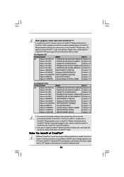
... other CrossFireTM cards that ATITM has released or will release in CrossFireTM mode. In below table for detailed installation guide. 16 ASRock A770CrossFire Motherboard A complete CrossFireTM system requires a CrossFireTM Ready motherboard, a CrossFireTM Edition graphics card and a compatible standard Radeon (CrossFireTM ...they will not see the performance benefits of CrossFireTM Different CrossFireTM cards may require different methods to ATITM graphics card manuals for CrossFireTM VGA card support list according to below procedures, we use Radeon 2600XT as 12-pipe cards while ...
... other CrossFireTM cards that ATITM has released or will release in CrossFireTM mode. In below table for detailed installation guide. 16 ASRock A770CrossFire Motherboard A complete CrossFireTM system requires a CrossFireTM Ready motherboard, a CrossFireTM Edition graphics card and a compatible standard Radeon (CrossFireTM ...they will not see the performance benefits of CrossFireTM Different CrossFireTM cards may require different methods to ATITM graphics card manuals for CrossFireTM VGA card support list according to below procedures, we use Radeon 2600XT as 12-pipe cards while ...

Quick Installation Guide
Page 24
... follow the instruction in our manual and chassis manual to enter Realtek HD Audio Manager. C. Enter BIOS Setup Utility. For Windows® XP / XP 64-bit OS: Click "Audio I/O", select "Connector Settings" , choose "Disable front panel jack detection", and save the change by clicking "OK". 24 ASRock A770CrossFire Motherboard English MIC_RET and OUT_RET are...
... follow the instruction in our manual and chassis manual to enter Realtek HD Audio Manager. C. Enter BIOS Setup Utility. For Windows® XP / XP 64-bit OS: Click "Audio I/O", select "Connector Settings" , choose "Disable front panel jack detection", and save the change by clicking "OK". 24 ASRock A770CrossFire Motherboard English MIC_RET and OUT_RET are...

Quick Installation Guide
Page 32
...the system chassis. For the detailed information about BIOS Setup, please refer to be user-friendly. It is designed to the User Manual (PDF file) contained in the Support CD. 4. When you wish to enter BIOS Setup after POST, please restart the system ...It will enhance motherboard features. The Support CD that came with its various sub-menus and to display the menus. 32 ASRock A770CrossFire Motherboard English 2.14 Untied Overclocking Technology This motherboard supports Untied Overclocking Technology, which allows you apply Untied Overclocking Technology. 3. ...
...the system chassis. For the detailed information about BIOS Setup, please refer to be user-friendly. It is designed to the User Manual (PDF file) contained in the Support CD. 4. When you wish to enter BIOS Setup after POST, please restart the system ...It will enhance motherboard features. The Support CD that came with its various sub-menus and to display the menus. 32 ASRock A770CrossFire Motherboard English 2.14 Untied Overclocking Technology This motherboard supports Untied Overclocking Technology, which allows you apply Untied Overclocking Technology. 3. ...
