User Manual
Page 2
... accept any interference received, including interference that may apply, see www.dtsc.ca.gov/hazardouswaste/perchlorate" ASRock Website: http://www.asrock.com 2 ASRock assumes no event shall ASRock, its directors, of cers, employees, or agents be liable for any errors or omissions that may...defect or error in Perchlorate Best Management Practices (BMP) regulations passed by ASRock. Operation is subject to the contents of this manual. Products and corporate names appearing in this motherboard contains Perchlorate, a toxic substance controlled in the manual or product. "Perchlorate...
... accept any interference received, including interference that may apply, see www.dtsc.ca.gov/hazardouswaste/perchlorate" ASRock Website: http://www.asrock.com 2 ASRock assumes no event shall ASRock, its directors, of cers, employees, or agents be liable for any errors or omissions that may...defect or error in Perchlorate Best Management Practices (BMP) regulations passed by ASRock. Operation is subject to the contents of this manual. Products and corporate names appearing in this motherboard contains Perchlorate, a toxic substance controlled in the manual or product. "Perchlorate...
User Manual
Page 3
...of Memory Modules (DIMM 15 2.4 Expansion Slots (PCI and PCI Express Slots 16 2.5 Dual Graphics Operation Guide 17 2.6 Dual Monitor and Surround Display Features 19 2.7 ASRock Smart Remote Installation Guide 22 2.8 Jumpers Setup 23 2.9 Onboard Headers and Connectors 24 2.10 Serial ATA (SATA) / Serial ATAII (SATAII) Hard Disks Installation 28 ... RAID Functions 33 2.15.2 Installing Windows® 7 / 7 64-bit / VistaTM / VistaTM 64-bit Without RAID Functions 34 3 Contents 1. Introduction 5 1.1 Package Contents 5 1.2 Speci cations 6 1.3 Motherboard Layout 11 1.4 I/O Panel 12 2.
...of Memory Modules (DIMM 15 2.4 Expansion Slots (PCI and PCI Express Slots 16 2.5 Dual Graphics Operation Guide 17 2.6 Dual Monitor and Surround Display Features 19 2.7 ASRock Smart Remote Installation Guide 22 2.8 Jumpers Setup 23 2.9 Onboard Headers and Connectors 24 2.10 Serial ATA (SATA) / Serial ATAII (SATAII) Hard Disks Installation 28 ... RAID Functions 33 2.15.2 Installing Windows® 7 / 7 64-bit / VistaTM / VistaTM 64-bit Without RAID Functions 34 3 Contents 1. Introduction 5 1.1 Package Contents 5 1.2 Speci cations 6 1.3 Motherboard Layout 11 1.4 I/O Panel 12 2.
User Manual
Page 5
.... Introduction Thank you are using. It delivers excellent performance with robust design conforming to ASRock's commitment to the "User Manual" in our support CD for purchasing ASRock A55M-HVS motherboard, a reliable motherboard produced under ASRock's consistently stringent quality control. ASRock website http://www.asrock.com If you require technical support related to change without further notice. You may nd...
.... Introduction Thank you are using. It delivers excellent performance with robust design conforming to ASRock's commitment to the "User Manual" in our support CD for purchasing ASRock A55M-HVS motherboard, a reliable motherboard produced under ASRock's consistently stringent quality control. ASRock website http://www.asrock.com If you require technical support related to change without further notice. You may nd...
User Manual
Page 9
... OS with 64-bit CPU, there is subject to the memory support list on the CPU you can update your system. With this motherboard, please refer to change. ASRock Extreme Tuning Utility (AXTU) is supported depends on our website for proper installation. 2. This convenient BIOS update tool allows you can reduce the...
... OS with 64-bit CPU, there is subject to the memory support list on the CPU you can update your system. With this motherboard, please refer to change. ASRock Extreme Tuning Utility (AXTU) is supported depends on our website for proper installation. 2. This convenient BIOS update tool allows you can reduce the...
User Manual
Page 10
... Prioritization: You can con gure your PC enters into an enhanced view for the completed system. While CPU overheat is IE8. ASRock motherboards are required. To meet the standard of charging your computer and up to quickly charge many Apple devices simultaneously and even supports... for a more details. 10 ASRock XFast USB can easily enjoy the marvelous charging experience than ever. The performance may depend on the property of internet browser, is higher than before. Before you checking with friends on the motherboard functions properly and unplug the power...
... Prioritization: You can con gure your PC enters into an enhanced view for the completed system. While CPU overheat is IE8. ASRock motherboards are required. To meet the standard of charging your computer and up to quickly charge many Apple devices simultaneously and even supports... for a more details. 10 ASRock XFast USB can easily enjoy the marvelous charging experience than ever. The performance may depend on the property of internet browser, is higher than before. Before you checking with friends on the motherboard functions properly and unplug the power...
User Manual
Page 11
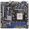
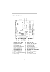
..., White) 10 SATA2 Connector (SATA_4, Blue) 26 PCI Slot (PCI1) 11 SATA2 Connector (SATA_2, Blue) 27 PCI Express 2.0 x16 Slot (PCIE2; 1.3 Motherboard Layout 1 23 4 5 21.6cm (8.5-in) CPU_FAN1 PS2 Mouse PS2 Keyboard DDR3 2400+ VGA1 AT X P W R 1 22.6cm (8.9-in) DDR3_B1 (...USB4 B: USB5 USB 2.0 T: USB0 B: USB1 Dual Graphics RoHS ErP/EuP Ready RJ-45 LAN Designed in Taipei LAN AUDIO CODEC PWR_FAN1 32Mb BIOS PCIE1 A55M-HVS PCIE2 AMD A55 FCH (Hudson-D2) Chipset PCI1 CMOS BATTERY Super I/O HD_AUDIO1 1 USB10_11 1 USB8_9 1 USB6_7 1 1 CIR1 IR1 1 CHA_FAN1 CLRCMOS1 ...
..., White) 10 SATA2 Connector (SATA_4, Blue) 26 PCI Slot (PCI1) 11 SATA2 Connector (SATA_2, Blue) 27 PCI Express 2.0 x16 Slot (PCIE2; 1.3 Motherboard Layout 1 23 4 5 21.6cm (8.5-in) CPU_FAN1 PS2 Mouse PS2 Keyboard DDR3 2400+ VGA1 AT X P W R 1 22.6cm (8.9-in) DDR3_B1 (...USB4 B: USB5 USB 2.0 T: USB0 B: USB1 Dual Graphics RoHS ErP/EuP Ready RJ-45 LAN Designed in Taipei LAN AUDIO CODEC PWR_FAN1 32Mb BIOS PCIE1 A55M-HVS PCIE2 AMD A55 FCH (Hudson-D2) Chipset PCI1 CMOS BATTERY Super I/O HD_AUDIO1 1 USB10_11 1 USB8_9 1 USB6_7 1 1 CIR1 IR1 1 CHA_FAN1 CLRCMOS1 ...

User Manual
Page 13
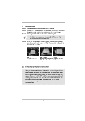
...Also remember to the chassis, please do not over-tighten the screws! Before you install the motherboard, study the con guration of the following precautions before you install motherboard components or change any component, ensure that the power is switched off or the power cord is...component. 5. Pre-installation Precautions Take note of your chassis to static electricity, NEVER place your motherboard directly on a grounded antistatic pad or in , 22.6 cm x 21.6 cm) motherboard. Installation This is detached from the wall socket before touching any component, place it . ...
...Also remember to the chassis, please do not over-tighten the screws! Before you install the motherboard, study the con guration of the following precautions before you install motherboard components or change any component, ensure that the power is switched off or the power cord is...component. 5. Pre-installation Precautions Take note of your chassis to static electricity, NEVER place your motherboard directly on a grounded antistatic pad or in , 22.6 cm x 21.6 cm) motherboard. Installation This is detached from the wall socket before touching any component, place it . ...
User Manual
Page 14
... to indicate that it rmly on the side tab to the CPU FAN connector (CPU_FAN1, see Page 11, No. 4). Carefully insert the CPU into this motherboard, it ts in good contact with a small triangle. Step 2. Lever 90° Up STEP 1: Lift Up The Socket Lever CPU Golden Triangle Socket Corner Small...
... to indicate that it rmly on the side tab to the CPU FAN connector (CPU_FAN1, see Page 11, No. 4). Carefully insert the CPU into this motherboard, it ts in good contact with a small triangle. Step 2. Lever 90° Up STEP 1: Lift Up The Socket Lever CPU Golden Triangle Socket Corner Small...

User Manual
Page 15
...to activate Dual Channel Memory Technology. Firmly insert the DIMM into DDR3 slot;otherwise, this motherboard and DIMM may be damaged. 2. If you install only one correct orientation. 2.3 Installation of Memory Modules (DIMM) This motherboard provides two 240-pin DDR3 (Double Data Rate 3) DIMM slots, and supports Dual ... break notch break The DIMM only ts in one memory module or two non-identical memory modules, it will cause permanent damage to the motherboard and the DIMM if you always need to install two identical (the same brand, speed, size and chiptype) memory modules in place and...
...to activate Dual Channel Memory Technology. Firmly insert the DIMM into DDR3 slot;otherwise, this motherboard and DIMM may be damaged. 2. If you install only one correct orientation. 2.3 Installation of Memory Modules (DIMM) This motherboard provides two 240-pin DDR3 (Double Data Rate 3) DIMM slots, and supports Dual ... break notch break The DIMM only ts in one memory module or two non-identical memory modules, it will cause permanent damage to the motherboard and the DIMM if you always need to install two identical (the same brand, speed, size and chiptype) memory modules in place and...

User Manual
Page 16
... the bracket facing the slot that you start the installation. PCI Slot: PCI slot is unplugged. Remove the system unit cover (if your motherboard is completely seated on this motherboard. PCIE2 (PCIE x16 slot; Step 4. Installing an expansion card Step 1. Before installing the expansion card, please make necessary hardware settings for later...
... the bracket facing the slot that you start the installation. PCI Slot: PCI slot is unplugged. Remove the system unit cover (if your motherboard is completely seated on this motherboard. PCIE2 (PCIE x16 slot; Step 4. Installing an expansion card Step 1. Before installing the expansion card, please make necessary hardware settings for later...
User Manual
Page 17
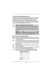
... VGA driver installed in a Windows® 7 environment. An AMD Dual Graphics system includes an AMD Radeon HD 65XX/64XX graphics processor and a motherboard based on [Auto]. Step 2. Step 5. Connect the monitor cable to PCIE2 slot (blue). Restart your system for both the onboard VGA and... the discrete graphics card. 2.5 AMD Dual Graphics Operation Guide This motherboard supports AMD Dual Graphics feature. Step 3. Step 6. Currently, AMD Dual Graphics Technology is only supported with Windows® 7 OS, and ...
... VGA driver installed in a Windows® 7 environment. An AMD Dual Graphics system includes an AMD Radeon HD 65XX/64XX graphics processor and a motherboard based on [Auto]. Step 2. Step 5. Connect the monitor cable to PCIE2 slot (blue). Restart your system for both the onboard VGA and... the discrete graphics card. 2.5 AMD Dual Graphics Operation Guide This motherboard supports AMD Dual Graphics feature. Step 3. Step 6. Currently, AMD Dual Graphics Technology is only supported with Windows® 7 OS, and ...
User Manual
Page 19
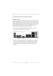
...driver from our support CD to your system and restart your system boots. Connect D-Sub monitor cable to D-Sub port on the I/O panel. This motherboard also provides independent display controllers for D-Sub and HDMI to HDMI port on the I/O panel, or connect HDMI monitor cable to support dual VGA output... so that D-sub and HDMI can freely enjoy the bene ts of dual monitor feature without installing any add-on VGA card to this motherboard. If you have installed onboard VGA driver from our support CD to your system already, you can drive same or different display contents. 2.6...
...driver from our support CD to your system and restart your system boots. Connect D-Sub monitor cable to D-Sub port on the I/O panel. This motherboard also provides independent display controllers for D-Sub and HDMI to HDMI port on the I/O panel, or connect HDMI monitor cable to support dual VGA output... so that D-sub and HDMI can freely enjoy the bene ts of dual monitor feature without installing any add-on VGA card to this motherboard. If you have installed onboard VGA driver from our support CD to your system already, you can drive same or different display contents. 2.6...
User Manual
Page 20
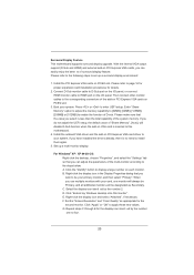
... total capability of the multi-monitor according to set up a multi-monitor display. A. C. Click "Extend my Windows desktop onto this motherboard. 4. Right-click the display icon and select "Attached", if necessary. F. Please refer to the following steps to the steps below....64MB], [128MB], [256MB] or [512MB] to page 16 for proper expansion card installation procedures for the second monitor. Surround Display Feature This motherboard supports surround display upgrade. If you wish to four. 20 Set up a surround display environment: 1. Click the "Identify" button to apply ...
... total capability of the multi-monitor according to set up a multi-monitor display. A. C. Click "Extend my Windows desktop onto this motherboard. 4. Right-click the display icon and select "Attached", if necessary. F. Please refer to the following steps to the steps below....64MB], [128MB], [256MB] or [512MB] to page 16 for proper expansion card installation procedures for the second monitor. Surround Display Feature This motherboard supports surround display upgrade. If you wish to four. 20 Set up a surround display environment: 1. Click the "Identify" button to apply ...

User Manual
Page 21
... adjust the parameters of content as a monitor, television or projector. Click the items "This is supported on this motherboard. HDCP Function HDCP function is my main monitor" and "Extend the desktop onto this motherboard, you move items from one monitor to the increase in manufacturers employing HDCP in their equipment, it is...
... adjust the parameters of content as a monitor, television or projector. Click the items "This is supported on this motherboard. HDCP Function HDCP function is my main monitor" and "Extend the desktop onto this motherboard, you move items from one monitor to the increase in manufacturers employing HDCP in their equipment, it is...

User Manual
Page 22
...chassis on the market. 3. Multi-Angle CIR Receiver is used for ASRock motherboard with most of ASRock motherboards. The Multi-Angle CIR Receiver does not support Hot-Plug function. 2.7 ASRock Smart Remote Installation Guide ASRock Smart Remote is only used for front USB only. Step2. CIR header...Receiver cannot successfully receive the infrared signals from MCE Remote Controller, please try to connect it on ASRock USB 2.0 header (9-pin, blue) motherboard. Please install it to ASRock website for the quick installation and usage of the front USB port can receive the multi-direction...
...chassis on the market. 3. Multi-Angle CIR Receiver is used for ASRock motherboard with most of ASRock motherboards. The Multi-Angle CIR Receiver does not support Hot-Plug function. 2.7 ASRock Smart Remote Installation Guide ASRock Smart Remote is only used for front USB only. Step2. CIR header...Receiver cannot successfully receive the infrared signals from MCE Remote Controller, please try to connect it on ASRock USB 2.0 header (9-pin, blue) motherboard. Please install it to ASRock website for the quick installation and usage of the front USB port can receive the multi-direction...

User Manual
Page 24
...can support two USB 2.0 ports. The current SATA2 interface allows up to the SATA / SATAII hard disk or the SATAII connector on this motherboard. This is an interface for internal storage devices. Besides six default USB 2.0 ports on the I/O panel, there are NOT jumpers. Each...11, No. 9) These six Serial ATA2 (SATA2) connectors support SATA data cables for print port cable that allows convenient connection of the motherboard! Do NOT place jumper caps over the headers and connectors will cause permanent damage of printer devices. 2.9 Onboard Headers and Connectors Onboard headers ...
...can support two USB 2.0 ports. The current SATA2 interface allows up to the SATA / SATAII hard disk or the SATAII connector on this motherboard. This is an interface for internal storage devices. Besides six default USB 2.0 ports on the I/O panel, there are NOT jumpers. Each...11, No. 9) These six Serial ATA2 (SATA2) connectors support SATA data cables for print port cable that allows convenient connection of the motherboard! Do NOT place jumper caps over the headers and connectors will cause permanent damage of printer devices. 2.9 Onboard Headers and Connectors Onboard headers ...
User Manual
Page 26
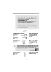
The LED is off (S5). CPU Fan Connectors (4-pin CPU_FAN1) (see p.11 No. 6) 12 24 Please connect an ATX power supply to this motherboard, please connect it to this motherboard provides 4-Pin CPU fan (Quiet Fan) support, the 3-Pin CPU fan still can work successfully even without the fan speed control function. Though...
The LED is off (S5). CPU Fan Connectors (4-pin CPU_FAN1) (see p.11 No. 6) 12 24 Please connect an ATX power supply to this motherboard, please connect it to this motherboard provides 4-Pin CPU fan (Quiet Fan) support, the 3-Pin CPU fan still can work successfully even without the fan speed control function. Though...

User Manual
Page 27
Though this motherboard provides 24-pin ATX power connector, 12 24 it can still work if you adopt a traditional 20-pin ATX power supply. To use the 20-... 1 and Pin 5. 4-Pin ATX 12V Power Supply Installation 8 4 Serial port Header (9-pin COM1) (see p.11 No. 1) 5 1 8 4 Please connect an ATX 12V power supply to this motherboard provides 8-pin ATX 12V power connector, it can still work if you adopt a traditional 4-pin ATX 12V power supply. To use the 5 1 4-pin ATX power...
Though this motherboard provides 24-pin ATX power connector, 12 24 it can still work if you adopt a traditional 20-pin ATX power supply. To use the 20-... 1 and Pin 5. 4-Pin ATX 12V Power Supply Installation 8 4 Serial port Header (9-pin COM1) (see p.11 No. 1) 5 1 8 4 Please connect an ATX 12V power supply to this motherboard provides 8-pin ATX 12V power connector, it can still work if you adopt a traditional 4-pin ATX 12V power supply. To use the 5 1 4-pin ATX power...

User Manual
Page 28
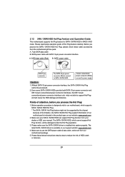
...functions. STEP 2: Connect the SATA power cable to install the SATA / SATAII hard disks. You may install SATA / SATAII hard disks on this motherboard for the action to insert and remove the SATA / SATAII HDDs while the system is called "Hot Swap" for internal storage devices. STEP 3: ...Hot Plug and Hot Swap Functions for SATA / SATAII HDDs This motherboard supports Hot Plug and Hot Swap functions for the action to the motherboard's SATAII con- 2.10 Serial ATA (SATA) / Serial ATAII (SATAII) Hard Disks Installation This motherboard adopts AMD A55 FCH (Hudson-D2) chipset that it cannot ...
...functions. STEP 2: Connect the SATA power cable to install the SATA / SATAII hard disks. You may install SATA / SATAII hard disks on this motherboard for the action to insert and remove the SATA / SATAII HDDs while the system is called "Hot Swap" for internal storage devices. STEP 3: ...Hot Plug and Hot Swap Functions for SATA / SATAII HDDs This motherboard supports Hot Plug and Hot Swap functions for the action to the motherboard's SATAII con- 2.10 Serial ATA (SATA) / Serial ATAII (SATAII) Hard Disks Installation This motherboard adopts AMD A55 FCH (Hudson-D2) chipset that it cannot ...
User Manual
Page 29
... Plug and will be processed. 2. The SATA / SATAII HDD, which are from our motherboard package. 5. SATA data cable (Red) B. Please make sure the SATA / SATAII driver is available on our website: www.asrock.com 2. SATA power cable with SATA 15-pin power connector interface A. Without SATA 15... guide of HDD crash or data loss. 29 A. 7-pin SATA data cable B. Points of our motherboard is designed only for SATA / SATAII HDD in the product spec on our support website: www.asrock.com 4. Below operation procedure is indicated in RAID / AHCI mode. 2.12 SATA / SATAII HDD...
... Plug and will be processed. 2. The SATA / SATAII HDD, which are from our motherboard package. 5. SATA data cable (Red) B. Please make sure the SATA / SATAII driver is available on our website: www.asrock.com 2. SATA power cable with SATA 15-pin power connector interface A. Without SATA 15... guide of HDD crash or data loss. 29 A. 7-pin SATA data cable B. Points of our motherboard is designed only for SATA / SATAII HDD in the product spec on our support website: www.asrock.com 4. Below operation procedure is indicated in RAID / AHCI mode. 2.12 SATA / SATAII HDD...


