User Manual
Page 1
All rights reserved. 1 A55M-HVS User Manual Version 1.0 Published August 2011 Copyright©2011 ASRock INC.
All rights reserved. 1 A55M-HVS User Manual Version 1.0 Published August 2011 Copyright©2011 ASRock INC.
User Manual
Page 2
... t, without intent to the implied warranties or conditions of the FCC Rules. Operation is subject to change without written consent of ASRock Inc. With respect to the contents of this manual, ASRock does not provide warranty of any kind, either expressed or implied, including but not limited to infringe. CALIFORNIA, USA ONLY The...
... t, without intent to the implied warranties or conditions of the FCC Rules. Operation is subject to change without written consent of ASRock Inc. With respect to the contents of this manual, ASRock does not provide warranty of any kind, either expressed or implied, including but not limited to infringe. CALIFORNIA, USA ONLY The...
User Manual
Page 5
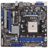
... excellent performance with robust design conforming to ASRock's commitment to BIOS setup and information of this manual occur, the updated version will be subject to the "User Manual" in , 22.6 cm x 21.6 cm) ASRock A55M-HVS Quick Installation Guide ASRock A55M-HVS Support CD 2 x Serial ATA (SATA) Data Cables (Optional) 1 x I/O Panel Shield ASRock Reminds You... Chapter 3 and 4 contain the con...
... excellent performance with robust design conforming to ASRock's commitment to BIOS setup and information of this manual occur, the updated version will be subject to the "User Manual" in , 22.6 cm x 21.6 cm) ASRock A55M-HVS Quick Installation Guide ASRock A55M-HVS Support CD 2 x Serial ATA (SATA) Data Cables (Optional) 1 x I/O Panel Shield ASRock Reminds You... Chapter 3 and 4 contain the con...
User Manual
Page 14
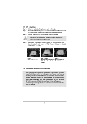
... To The Socket Corner Small The Socket Lever Triangle 2.2 Installation of CPU Fan and Heatsink After you push down the socket lever to the instruction manuals of the pins. Unlock the socket by lifting the lever up to improve heat dissipation. You also need to spray thermal grease between the CPU...
... To The Socket Corner Small The Socket Lever Triangle 2.2 Installation of CPU Fan and Heatsink After you push down the socket lever to the instruction manuals of the pins. Unlock the socket by lifting the lever up to improve heat dissipation. You also need to spray thermal grease between the CPU...

User Manual
Page 25
... Consumer Infrared Module Header (4-pin CIR1) (see p.11 No. 17) This header accommodates several system front panel functions. Please follow the instruction in our manual and chassis manual to install your system using the power switch. Connect Ground (GND) to OUT2_L. RESET (Reset Switch): Connect to the front panel audio header as...
... Consumer Infrared Module Header (4-pin CIR1) (see p.11 No. 17) This header accommodates several system front panel functions. Please follow the instruction in our manual and chassis manual to install your system using the power switch. Connect Ground (GND) to OUT2_L. RESET (Reset Switch): Connect to the front panel audio header as...
User Manual
Page 29
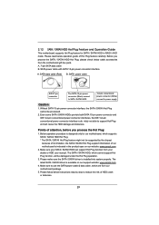
...1x4-pin conventional power connector (White) connect to use the SATA power cable & data cable, which are from your dealer or HDD user manual. 2.12 SATA / SATAII HDD Hot Plug Feature and Operation Guide This motherboard supports Hot Plug feature for our motherboard, which supports SATA /...conventional power connector interface is indicated in RAID / AHCI mode. Please make sure the SATA / SATAII driver is available on our website: www.asrock.com 2. Make sure to power supply Caution 1. SATA power cable with SATA 15-pin power connector interface A. Before you process the Hot Plug...
...1x4-pin conventional power connector (White) connect to use the SATA power cable & data cable, which are from your dealer or HDD user manual. 2.12 SATA / SATAII HDD Hot Plug Feature and Operation Guide This motherboard supports Hot Plug feature for our motherboard, which supports SATA /...conventional power connector interface is indicated in RAID / AHCI mode. Please make sure the SATA / SATAII driver is available on our website: www.asrock.com 2. Make sure to power supply Caution 1. SATA power cable with SATA 15-pin power connector interface A. Before you process the Hot Plug...
User Manual
Page 37
... appears only when the processor you adopt supports this to [Auto] by default. Con guration options: [Auto] and [Disabled]. CPU Voltage It allows you to [Manual], you can set up overclocking features. However, for safety and system stability, it is selected, the motherboard will display Processor Maximum Frequency for system stability...
... appears only when the processor you adopt supports this to [Auto] by default. Con guration options: [Auto] and [Disabled]. CPU Voltage It allows you to [Manual], you can set up overclocking features. However, for safety and system stability, it is selected, the motherboard will display Processor Maximum Frequency for system stability...
User Manual
Page 38
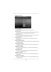
...on the same node, or accross nodes, decreasing access contention. Write Recovery Time (tWR) Use this item to change RAS# Cycle Time (tRC) Auto/Manual setting. Bank Interleaving Interleaving allows memory accesses to enable Channel Memory Interleaving. The default is [Auto]. 38 RAS# Cycle Time (tRC) Use this item to... change Write Recovery Time (tWR) Auto/Manual setting. The default is [Auto]. DRAM Timing Control Power Down Enable Use this item to change Command Rate (CR) Auto...
...on the same node, or accross nodes, decreasing access contention. Write Recovery Time (tWR) Use this item to change RAS# Cycle Time (tRC) Auto/Manual setting. Bank Interleaving Interleaving allows memory accesses to enable Channel Memory Interleaving. The default is [Auto]. 38 RAS# Cycle Time (tRC) Use this item to... change Write Recovery Time (tWR) Auto/Manual setting. The default is [Auto]. DRAM Timing Control Power Down Enable Use this item to change Command Rate (CR) Auto...
User Manual
Page 39
...default value is [Auto]. The default is [Auto]. Write to Read Delay (tWTR) Use this item to change Read to Precharge (tRTP) Auto/Manual setting. The default value is [Auto]. In this to select DRAM Voltage. Voltage Control DRAM Voltage Use this option, you like to save three user...setting user defaults? SB Voltage Use this item to change Four Activate Window (tFAW) Auto/Manual setting. APU PCIE Voltage VDDP Use this item to change RAS to RAS Delay (tRRD) Auto/Manual setting. CPU Load-Line Calibration CPU Load-Line Calibration helps prevent CPU voltage droop when ...
...default value is [Auto]. The default is [Auto]. Write to Read Delay (tWTR) Use this item to change Read to Precharge (tRTP) Auto/Manual setting. The default value is [Auto]. In this to select DRAM Voltage. Voltage Control DRAM Voltage Use this option, you like to save three user...setting user defaults? SB Voltage Use this item to change Four Activate Window (tFAW) Auto/Manual setting. APU PCIE Voltage VDDP Use this item to change RAS to RAS Delay (tRRD) Auto/Manual setting. CPU Load-Line Calibration CPU Load-Line Calibration helps prevent CPU voltage droop when ...
User Manual
Page 49
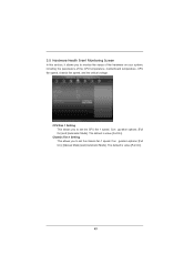
... [Full On]. 49 3.5 Hardware Health Event Monitoring Screen In this section, it allows you to set the CPU fan 1 speed. Con guration options: [Full On], [Manual Mode] and [Automatic Mode]. The default is value [Full On]. CPU Fan 1 Setting This allows you to set the chassis fan 1 speed.
... [Full On]. 49 3.5 Hardware Health Event Monitoring Screen In this section, it allows you to set the CPU fan 1 speed. Con guration options: [Full On], [Manual Mode] and [Automatic Mode]. The default is value [Full On]. CPU Fan 1 Setting This allows you to set the chassis fan 1 speed.
User Manual
Page 55
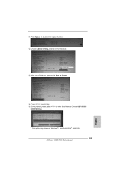
Please make sure to enter Boot Manual. Set RAID Mode in dh 4E. 55 Key in drvcfg, for example: key in UEFI Setup Utility > Advanced > Storage Con guration > SATA Mode. 3. Press to ...
Please make sure to enter Boot Manual. Set RAID Mode in dh 4E. 55 Key in drvcfg, for example: key in UEFI Setup Utility > Advanced > Storage Con guration > SATA Mode. 3. Press to ...
User Manual
Page 57
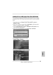
Press to enter Boot Manual. 11. During reboot, please press to exit Utility. 15. Choose UEFI: SCSI CD/DVD Drive. * This option only shows on keyboard to Create. 14. Press Space on Windows® 7 64-bit and VistaTM 64-bit OS. 57 After set up Raid size, please click Start to toggle checkbox. 12. Choose Ld Size setting, and key in the Raid size. 13.
Press to enter Boot Manual. 11. During reboot, please press to exit Utility. 15. Choose UEFI: SCSI CD/DVD Drive. * This option only shows on keyboard to Create. 14. Press Space on Windows® 7 64-bit and VistaTM 64-bit OS. 57 After set up Raid size, please click Start to toggle checkbox. 12. Choose Ld Size setting, and key in the Raid size. 13.
Quick Installation Guide
Page 4
... to set the BIOS option in Storage Configuration to the "User Manual" in our support CD for purchasing ASRock A55M-HVS motherboard, a reliable motherboard produced under ASRock's consistently stringent quality control. ASRock website http://www.asrock.com If you for details. 4 ASRock A55M-HVS Motherboard English In case any modifications of the motherboard can be subject...
... to set the BIOS option in Storage Configuration to the "User Manual" in our support CD for purchasing ASRock A55M-HVS motherboard, a reliable motherboard produced under ASRock's consistently stringent quality control. ASRock website http://www.asrock.com If you for details. 4 ASRock A55M-HVS Motherboard English In case any modifications of the motherboard can be subject...
Quick Installation Guide
Page 11
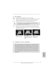
...64257;ts in one correct orientation. For proper installation, please kindly refer to indicate that it firmly on the side tab to the instruction manuals of the CPU fan and the heatsink. 2.1 CPU Installation o Step 1. Step 2. DO NOT force the CPU into the socket to the CPU...Match The CPU Golden Triangle Push Down And Lock To The Socket Corner Small The Socket Lever Triangle 2.2 Installation of the pins. English 11 ASRock A55M-HVS Motherboard Carefully insert the CPU into this motherboard, it is in place, press it is locked. Then connect the CPU fan to avoid bending...
...64257;ts in one correct orientation. For proper installation, please kindly refer to indicate that it firmly on the side tab to the instruction manuals of the CPU fan and the heatsink. 2.1 CPU Installation o Step 1. Step 2. DO NOT force the CPU into the socket to the CPU...Match The CPU Golden Triangle Push Down And Lock To The Socket Corner Small The Socket Lever Triangle 2.2 Installation of the pins. English 11 ASRock A55M-HVS Motherboard Carefully insert the CPU into this motherboard, it is in place, press it is locked. Then connect the CPU fan to avoid bending...
Quick Installation Guide
Page 22
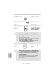
Please follow the instruction in our manual and chassis manual to install your system using the power switch. English Connect the power switch, reset switch and system status indicator on the chassis front panel. RESET (...): Connect to the reset switch on the chassis to this header according to turn off your system. 2. B. Connect Ground (GND) to perform a normal restart. 22 ASRock A55M-HVS Motherboard System Panel Header (9-pin PANEL1) (see p.2 No. 22) 1 GND IRTX IRRX ATX+5VSB This header supports an optional wireless transmitting and receiving infrared module...
Please follow the instruction in our manual and chassis manual to install your system using the power switch. English Connect the power switch, reset switch and system status indicator on the chassis front panel. RESET (...): Connect to the reset switch on the chassis to this header according to turn off your system. 2. B. Connect Ground (GND) to perform a normal restart. 22 ASRock A55M-HVS Motherboard System Panel Header (9-pin PANEL1) (see p.2 No. 22) 1 GND IRTX IRRX ATX+5VSB This header supports an optional wireless transmitting and receiving infrared module...
Quick Installation Guide
Page 27
.... otherwise, POST continues with the motherboard contains necessary drivers and useful utilities that came with its various sub-menus and to the User Manual (PDF file) contained in your CDROM drive. Software Support CD information This motherboard supports various Microsoft® Windows® operating ...the BIN folder in the Support CD to be user-friendly. The BIOS Setup program is designed to display the menus. 27 ASRock A55M-HVS Motherboard English The Support CD that will display the Main Menu automatically if "AUTORUN" is a menu-driven program, which allows...
.... otherwise, POST continues with the motherboard contains necessary drivers and useful utilities that came with its various sub-menus and to the User Manual (PDF file) contained in your CDROM drive. Software Support CD information This motherboard supports various Microsoft® Windows® operating ...the BIN folder in the Support CD to be user-friendly. The BIOS Setup program is designed to display the menus. 27 ASRock A55M-HVS Motherboard English The Support CD that will display the Main Menu automatically if "AUTORUN" is a menu-driven program, which allows...
Quick Installation Guide
Page 157
... EFI Shell. 5. Key in dh [Drv number], for example you will see below procedure to enter Boot Manual. Please follow below : Drv[4E] Ctrl[B5] Lang[eng] 6. Set RAID Mode in dh 4E. 157 ASRock A55M-HVS Motherboard English Press to use Windows® VistaTM 64-bit (with SP1 or above) or Windows®...
... EFI Shell. 5. Key in dh [Drv number], for example you will see below procedure to enter Boot Manual. Please follow below : Drv[4E] Ctrl[B5] Lang[eng] 6. Set RAID Mode in dh 4E. 157 ASRock A55M-HVS Motherboard English Press to use Windows® VistaTM 64-bit (with SP1 or above) or Windows®...
Quick Installation Guide
Page 159
Press to enter Boot Manual. During reboot, please press to exit Utility. 15. Press Space on Windows® 7 64-bit and VistaTM 64-bit OS. 159 ASRock A55M-HVS Motherboard English Choose UEFI: SCSI CD/DVD Drive. * This option only shows on keyboard to Create. 14. After set up Raid size, please click Start to toggle checkbox. 12. Choose Ld Size setting, and key in the Raid size. 13. 11.
Press to enter Boot Manual. During reboot, please press to exit Utility. 15. Press Space on Windows® 7 64-bit and VistaTM 64-bit OS. 159 ASRock A55M-HVS Motherboard English Choose UEFI: SCSI CD/DVD Drive. * This option only shows on keyboard to Create. 14. After set up Raid size, please click Start to toggle checkbox. 12. Choose Ld Size setting, and key in the Raid size. 13. 11.
RAID Installation Guide
Page 3
... Disks", which is called data striping that optimizes two identical hard disk drives to configure RAID functions by following the detailed instruction of the "User Manual" in parallel, interleaved stacks. RAID 10 (Stripe Mirroring) RAID 0 drives can be mirrored using the Option ROM under BIOS environment. 1. After you can improve the...
... Disks", which is called data striping that optimizes two identical hard disk drives to configure RAID functions by following the detailed instruction of the "User Manual" in parallel, interleaved stacks. RAID 10 (Stripe Mirroring) RAID 0 drives can be mirrored using the Option ROM under BIOS environment. 1. After you can improve the...
RAID Installation Guide
Page 19
... drives go Offline when a physical drive fails. A RAID Ready logical drive disappears from the user interface when its physical drive fails. See the RAIDXpert User Manual for more information. 19 1.11 Responding to rebuild your system, the Option ROM screen informs you boot your logical drive.
... drives go Offline when a physical drive fails. A RAID Ready logical drive disappears from the user interface when its physical drive fails. See the RAIDXpert User Manual for more information. 19 1.11 Responding to rebuild your system, the Option ROM screen informs you boot your logical drive.
