
User Manual
Page 2
...incidental, or consequential damages (including damages for a particular purpose. Version 1.0 Published July 2020 Copyright©2020 ASRock INC. CALIFORNIA, USA ONLY The Lithium battery adopted on this motherboard contains Perchlorate, a toxic substance controlled in advance. All rights reserved. Copyright Notice: No part of this ...or fitness for loss of profits, loss of business, loss of data, interruption of business and the like), even if ASRock has been advised of the possibility of their respective companies, and are furnished for identification or explanation and to the owners'...
...incidental, or consequential damages (including damages for a particular purpose. Version 1.0 Published July 2020 Copyright©2020 ASRock INC. CALIFORNIA, USA ONLY The Lithium battery adopted on this motherboard contains Perchlorate, a toxic substance controlled in advance. All rights reserved. Copyright Notice: No part of this ...or fitness for loss of profits, loss of business, loss of data, interruption of business and the like), even if ASRock has been advised of the possibility of their respective companies, and are furnished for identification or explanation and to the owners'...

User Manual
Page 4
... Slots) 24 2.5 Jumpers Setup 25 2.6 Onboard Headers and Connectors 26 2.7 M.2_SSD (NGFF) Module Installation Guide 30 Chapter 3 Software and Utilities Operation 34 3.1 Installing Drivers 34 3.2 ASRock Motherboard Utility (A-Tuning) 35 3.2.1 Installing ASRock Motherboard Utility (A-Tuning) 35 3.2.2 Using ASRock Motherboard Utility (A-Tuning) 35 3.3 ASRock Live Update & APP Shop 38 3.3.1 UI Overview 38 3.3.2 Apps 39
... Slots) 24 2.5 Jumpers Setup 25 2.6 Onboard Headers and Connectors 26 2.7 M.2_SSD (NGFF) Module Installation Guide 30 Chapter 3 Software and Utilities Operation 34 3.1 Installing Drivers 34 3.2 ASRock Motherboard Utility (A-Tuning) 35 3.2.1 Installing ASRock Motherboard Utility (A-Tuning) 35 3.2.2 Using ASRock Motherboard Utility (A-Tuning) 35 3.3 ASRock Live Update & APP Shop 38 3.3.1 UI Overview 38 3.3.2 Apps 39
User Manual
Page 6
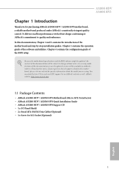
... guide of the software and utilities. ASRock website http://www.asrock.com. 1.1 Package Contents • ASRock A520M-HDV / A520M-HVS Motherboard (Micro ATX Form Factor) • ASRock A520M-HDV / A520M-HVS Quick Installation Guide • ASRock A520M-HDV / A520M-HVS Support CD • 1 x I/O Panel Shield • 2 x Serial ATA (SATA) Data Cables (Optional) • 1 x Screw for purchasing ASRock A520M-HDV / A520M-HVS motherboard, a reliable motherboard produced under ASRock's consistently stringent quality control. Because...
... guide of the software and utilities. ASRock website http://www.asrock.com. 1.1 Package Contents • ASRock A520M-HDV / A520M-HVS Motherboard (Micro ATX Form Factor) • ASRock A520M-HDV / A520M-HVS Quick Installation Guide • ASRock A520M-HDV / A520M-HVS Support CD • 1 x I/O Panel Shield • 2 x Serial ATA (SATA) Data Cables (Optional) • 1 x Screw for purchasing ASRock A520M-HDV / A520M-HVS motherboard, a reliable motherboard produced under ASRock's consistently stringent quality control. Because...

User Manual
Page 16
Doing so may cause physical injuries to you uninstall any components, place them on a carpet. A520M-HDV A520M-HVS Chapter 2 Installation This is a Micro ATX form factor motherboard. Failure to do so may damage the motherboard. 11 English Pre-installation Precautions Take note of your chassis to the chassis, please do not touch the ICs. •...
Doing so may cause physical injuries to you uninstall any components, place them on a carpet. A520M-HDV A520M-HVS Chapter 2 Installation This is a Micro ATX form factor motherboard. Failure to do so may damage the motherboard. 11 English Pre-installation Precautions Take note of your chassis to the chassis, please do not touch the ICs. •...

User Manual
Page 19
Installing the CPU Box Cooler SR1 1 2 14 English 2.2 Installing the CPU Fan and Heatsink After you install the CPU into this motherboard, it is necessary to install a larger heatsink and cooling fan to improve heat dissipation. Please turn off the power or remove the power cord before changing a CPU or heatsink. You also need to spray thermal grease between the CPU and the heatsink to dissipate heat. Make sure that the CPU and the heatsink are securely fastened and in good contact with each other.
Installing the CPU Box Cooler SR1 1 2 14 English 2.2 Installing the CPU Fan and Heatsink After you install the CPU into this motherboard, it is necessary to install a larger heatsink and cooling fan to improve heat dissipation. Please turn off the power or remove the power cord before changing a CPU or heatsink. You also need to spray thermal grease between the CPU and the heatsink to dissipate heat. Make sure that the CPU and the heatsink are securely fastened and in good contact with each other.

User Manual
Page 23
4 CPU_FAN1 *The diagrams shown here are for reference only. The headers might be in a different position on your motherboard. 18 English
4 CPU_FAN1 *The diagrams shown here are for reference only. The headers might be in a different position on your motherboard. 18 English

User Manual
Page 26
The headers might be in a different position on your motherboard. 21 English A520M-HDV A520M-HVS 5 CPU_FAN1 6 CPU_FAN1 +12V RGB_LED2 *The diagrams shown here are for reference only.
The headers might be in a different position on your motherboard. 21 English A520M-HDV A520M-HVS 5 CPU_FAN1 6 CPU_FAN1 +12V RGB_LED2 *The diagrams shown here are for reference only.

User Manual
Page 27
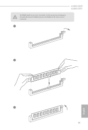
It is unable to activate Dual Channel Memory Technology with only one memory module installed. 3. otherwise, this motherboard and DIMM may be damaged. DR SR SR DR DR Frequency (Mhz) 3200 3200 3200 3200 3200 3200 Ryzen Series APUs (Renoir): UDIMM... - - For dual channel configuration, you always need to install a DDR, DDR2 or DDR3 memory module into a DDR4 slot; 2.3 Installing Memory Modules (DIMM) This motherboard provides two 288-pin DDR4 (Double Data Rate 4) DIMM slots, and supports Dual Channel Memory Technology. 1. AMD non-XMP Memory Frequency Support Ryzen Series CPUs...
It is unable to activate Dual Channel Memory Technology with only one memory module installed. 3. otherwise, this motherboard and DIMM may be damaged. DR SR SR DR DR Frequency (Mhz) 3200 3200 3200 3200 3200 3200 Ryzen Series APUs (Renoir): UDIMM... - - For dual channel configuration, you always need to install a DDR, DDR2 or DDR3 memory module into a DDR4 slot; 2.3 Installing Memory Modules (DIMM) This motherboard provides two 288-pin DDR4 (Double Data Rate 4) DIMM slots, and supports Dual Channel Memory Technology. 1. AMD non-XMP Memory Frequency Support Ryzen Series CPUs...
User Manual
Page 28
It will cause permanent damage to the motherboard and the DIMM if you force the DIMM into the slot at incorrect orientation. 1 2 3 23 English A520M-HDV A520M-HVS The DIMM only fits in one correct orientation.
It will cause permanent damage to the motherboard and the DIMM if you force the DIMM into the slot at incorrect orientation. 1 2 3 23 English A520M-HDV A520M-HVS The DIMM only fits in one correct orientation.

User Manual
Page 29
... slot) is used for PCI Express x1 lane width cards. 2.4 Expansion Slots (PCI Express Slots) There are 2 PCI Express slots on the motherboard. Please read the documentation of the expansion card and make sure that the power supply is switched off or the power cord is used for ...make necessary hardware settings for PCI Express x16 lane width graphics cards. For a better thermal environment, please connect a chassis fan to the motherboard's chassis fan connector (CHA_FAN1 or CHA_FAN2 ) when using multiple graphics cards. 24 English PCIe slots: PCIE1 (PCIe 3.0 x1 slot) is unplugged.
... slot) is used for PCI Express x1 lane width cards. 2.4 Expansion Slots (PCI Express Slots) There are 2 PCI Express slots on the motherboard. Please read the documentation of the expansion card and make sure that the power supply is switched off or the power cord is used for ...make necessary hardware settings for PCI Express x16 lane width graphics cards. For a better thermal environment, please connect a chassis fan to the motherboard's chassis fan connector (CHA_FAN1 or CHA_FAN2 ) when using multiple graphics cards. 24 English PCIe slots: PCIE1 (PCIe 3.0 x1 slot) is unplugged.

User Manual
Page 31
... header according to the reset switch on when the system is in S4 sleep state or powered off your chassis front panel module to the motherboard. PLED (System Power LED): Connect to turn off (S5). The LED is on the chassis front panel. English 26 You may differ by chassis. HDLED...
... header according to the reset switch on when the system is in S4 sleep state or powered off your chassis front panel module to the motherboard. PLED (System Power LED): Connect to turn off (S5). The LED is on the chassis front panel. English 26 You may differ by chassis. HDLED...

User Manual
Page 32
... OUT2_L J_SENSE OUT2_R MIC2_R MIC2_L This header is one header on this motherboard. These four SATA3 connectors support SATA data cables for connecting audio devices to the front audio panel. 27 English A520M-HDV A520M-HVS Chassis Intrusion and Speaker Header (7-pin SPK_CI1) (see p.6 or 7,...No. 6) (Lower) SPEAKER DUMMY DUMMY +5V 1 SIGNAL GND DUMMY SATA3_1 SATA3_3 SATA3_2 SATA3_4 Please connect the chassis intrusion and the chassis speaker to this motherboard. This USB 3.2 Gen1 header can support two ports. USB 2.0 Headers (9-pin USB_3_4) (see p.6 or 7, No. 11) (9-pin USB_5_6) (see...
... OUT2_L J_SENSE OUT2_R MIC2_R MIC2_L This header is one header on this motherboard. These four SATA3 connectors support SATA data cables for connecting audio devices to the front audio panel. 27 English A520M-HDV A520M-HVS Chassis Intrusion and Speaker Header (7-pin SPK_CI1) (see p.6 or 7,...No. 6) (Lower) SPEAKER DUMMY DUMMY +5V 1 SIGNAL GND DUMMY SATA3_1 SATA3_3 SATA3_2 SATA3_4 Please connect the chassis intrusion and the chassis speaker to this motherboard. This USB 3.2 Gen1 header can support two ports. USB 2.0 Headers (9-pin USB_3_4) (see p.6 or 7, No. 11) (9-pin USB_5_6) (see...

User Manual
Page 33
...Fan Connectors (4-pin CHA_FAN1) (see p.6 or 7, No. 17) (4-pin CHA_FAN2) (see p.6 or 7, No. 2) FAN_SPEED_CONTROL CPU_FAN_SPEED +12V GND 1 2 34 This motherboard provides a 4-Pin CPU fan (Quiet Fan) connector. FAN_SPEED_CONTROL CHA_FAN_SPEED FAN_VOLTAGE GND CPU Fan Connector (4-pin CPU_FAN1) (see p.6 or 7, No. 10) FAN_SPEED_CONTROL 4 CHA_FAN_SPEED ... system. 2. ATX Power Connector (24-pin ATXPWR1) (see p.6 or 7, No. 4) 12 24 1 13 This motherboard provides a 24-pin ATX power connector. Please follow the instructions in the Realtek Control panel and adjust "Recording Volume". ...
...Fan Connectors (4-pin CHA_FAN1) (see p.6 or 7, No. 17) (4-pin CHA_FAN2) (see p.6 or 7, No. 2) FAN_SPEED_CONTROL CPU_FAN_SPEED +12V GND 1 2 34 This motherboard provides a 4-Pin CPU fan (Quiet Fan) connector. FAN_SPEED_CONTROL CHA_FAN_SPEED FAN_VOLTAGE GND CPU Fan Connector (4-pin CPU_FAN1) (see p.6 or 7, No. 10) FAN_SPEED_CONTROL 4 CHA_FAN_SPEED ... system. 2. ATX Power Connector (24-pin ATXPWR1) (see p.6 or 7, No. 4) 12 24 1 13 This motherboard provides a 24-pin ATX power connector. Please follow the instructions in the Realtek Control panel and adjust "Recording Volume". ...

User Manual
Page 36
... insert the M.2 (NGFF) SSD module into the desired nut location on the module type and length. Hand tighten the standoff into the M.2 slot. C B A C B A C B A A520M-HDV A520M-HVS Step 3 Move the standoff based on the motherboard. Otherwise, release the standoff by default. Please be used. The standoff is placed at the nut location C by hand.
... insert the M.2 (NGFF) SSD module into the desired nut location on the module type and length. Hand tighten the standoff into the M.2 slot. C B A C B A C B A A520M-HDV A520M-HVS Step 3 Move the standoff based on the motherboard. Otherwise, release the standoff by default. Please be used. The standoff is placed at the nut location C by hand.
User Manual
Page 39
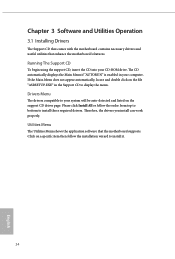
...order from top to bottom to your computer. Utilities Menu The Utilities Menu shows the application software that enhance the motherboard's features. Click on the support CD driver page. Chapter 3 Software and Utilities Operation 3.1 Installing Drivers The Support CD that comes... with the motherboard contains necessary drivers and useful utilities that the motherboard supports. The CD automatically displays the Main Menu if "AUTORUN" is enabled in the Support CD to install...
...order from top to bottom to your computer. Utilities Menu The Utilities Menu shows the application software that enhance the motherboard's features. Click on the support CD driver page. Chapter 3 Software and Utilities Operation 3.1 Installing Drivers The Support CD that comes... with the motherboard contains necessary drivers and useful utilities that the motherboard supports. The CD automatically displays the Main Menu if "AUTORUN" is enabled in the Support CD to install...
User Manual
Page 40
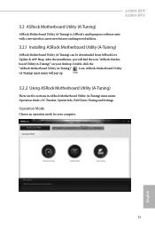
... your desktop. Double-click the "ASRock Motherboard Utility (A-Tuning)" icon, ASRock Motherboard Utility (A-Tuning) main menu will find the icon "ASRock Motherboard Utility (A-Tuning)" on your computer. 35 English A520M-HDV A520M-HVS 3.2 ASRock Motherboard Utility (A-Tuning) ASRock Motherboard Utility (A-Tuning) is ASRock's multi purpose software suite with a new interface, more new features and improved utilities. 3.2.1 Installing ASRock Motherboard Utility (A-Tuning) ASRock Motherboard Utility (A-Tuning) can be downloaded...
... your desktop. Double-click the "ASRock Motherboard Utility (A-Tuning)" icon, ASRock Motherboard Utility (A-Tuning) main menu will find the icon "ASRock Motherboard Utility (A-Tuning)" on your computer. 35 English A520M-HDV A520M-HVS 3.2 ASRock Motherboard Utility (A-Tuning) ASRock Motherboard Utility (A-Tuning) is ASRock's multi purpose software suite with a new interface, more new features and improved utilities. 3.2.1 Installing ASRock Motherboard Utility (A-Tuning) ASRock Motherboard Utility (A-Tuning) can be downloaded...
User Manual
Page 42
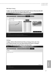
Settings Configure ASRock ASRock Motherboard Utility (A-Tuning). The fans will automatically shift to be launched when you want ASRock Motherboard Utility (A-Tuning) to the next speed level when the assigned temperature is met. Click to select "Auto run at Windows Startup" if you start up to five different fan speeds using the graph. A520M-HDV A520M-HVS FAN-Tastic Tuning Configure up the Windows operating system. 37 English
Settings Configure ASRock ASRock Motherboard Utility (A-Tuning). The fans will automatically shift to be launched when you want ASRock Motherboard Utility (A-Tuning) to the next speed level when the assigned temperature is met. Click to select "Auto run at Windows Startup" if you start up to five different fan speeds using the graph. A520M-HDV A520M-HVS FAN-Tastic Tuning Configure up the Windows operating system. 37 English

User Manual
Page 43
...: The information panel in the center displays data about the currently selected category and allows users to perform job-related tasks. With ASRock Live Update & APP Shop, you can quickly and easily install various apps and support utilities. Hot News: The hot news section...several category tabs or buttons that when selected the information panel below displays the relative information. 3.3 ASRock Live Update & APP Shop The ASRock Live Update & APP Shop is an online store for purchasing and downloading software applications for your motherboard up to date simply with a few clicks.
...: The information panel in the center displays data about the currently selected category and allows users to perform job-related tasks. With ASRock Live Update & APP Shop, you can quickly and easily install various apps and support utilities. Hot News: The hot news section...several category tabs or buttons that when selected the information panel below displays the relative information. 3.3 ASRock Live Update & APP Shop The ASRock Live Update & APP Shop is an online store for purchasing and downloading software applications for your motherboard up to date simply with a few clicks.

User Manual
Page 53
... IOD represents voltage for the VDDP. Infinity Fabric Frequency and Dividers AMD Overclocking Setup Set Infinity Fabric frequency (FCLK). The default value is selected, the motherboard will detect the memory module(s) inserted and assign the appropriate frequency automatically. Save User Default Type a profile name and press enter to overclock the memory...
... IOD represents voltage for the VDDP. Infinity Fabric Frequency and Dividers AMD Overclocking Setup Set Infinity Fabric frequency (FCLK). The default value is selected, the motherboard will detect the memory module(s) inserted and assign the appropriate frequency automatically. Save User Default Type a profile name and press enter to overclock the memory...

User Manual
Page 67
... Health Event Monitoring Screen This section allows you to monitor the status of the hardware on your system, including the parameters of the CPU temperature, motherboard temperature, fan speed and voltage.
... Health Event Monitoring Screen This section allows you to monitor the status of the hardware on your system, including the parameters of the CPU temperature, motherboard temperature, fan speed and voltage.


