
User Manual
Page 4
...1.2 Specifications 2 1.3 Motherboard Layout 6 1.4 I/O Panel 8 Chapter 2 Installation 9 2.1 Installing the CPU 10 2.2 Installing the CPU Fan and Heatsink 12 2.3 Installing Memory Modules (SO-DIMM) 14 2.4 Jumpers Setup 16 2.5 Onboard Headers and Connectors 18 2.6 M.2 WiFi/BT Module Installation Guide 22 2.7 M.2_SSD (NGFF) Module Installation Guide 24 Chapter 3 Software and Utilities Operation 29 3.1 Installing Drivers 29 Chapter 4 UEFI SETUP UTILITY 30 4.1 Introduction 30 4.1.1 UEFI Menu Bar 30 4.1.2 Navigation Keys 31 4.2 Main Screen 32 4.3 OC Tweaker Screen...
...1.2 Specifications 2 1.3 Motherboard Layout 6 1.4 I/O Panel 8 Chapter 2 Installation 9 2.1 Installing the CPU 10 2.2 Installing the CPU Fan and Heatsink 12 2.3 Installing Memory Modules (SO-DIMM) 14 2.4 Jumpers Setup 16 2.5 Onboard Headers and Connectors 18 2.6 M.2 WiFi/BT Module Installation Guide 22 2.7 M.2_SSD (NGFF) Module Installation Guide 24 Chapter 3 Software and Utilities Operation 29 3.1 Installing Drivers 29 Chapter 4 UEFI SETUP UTILITY 30 4.1 Introduction 30 4.1.1 UEFI Menu Bar 30 4.1.2 Navigation Keys 31 4.2 Main Screen 32 4.3 OC Tweaker Screen...
User Manual
Page 6
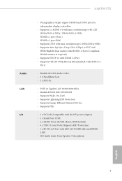
... Guide (Optional) • 1 x Thin-Mini ITX I/O Shield (Optional) • 1 x Mini ITX I/O Shield (Optional) • 1 x Serial ATA (SATA) Data Cable (Optional) • 1 x SATA Power Cable (Optional) • 2 x Screws for purchasing A320TM-ITX motherboard. Because the motherboard specifications and the BIOS software might be updated, the content of this documentation, Chapter 1 and 2 contains the introduction of the motherboard and step-by-step installation guides. Chapter 3 contains the operation guide of the BIOS setup. A320TM-ITX Chapter 1 Introduction Thank you for M.2 Sockets...
... Guide (Optional) • 1 x Thin-Mini ITX I/O Shield (Optional) • 1 x Mini ITX I/O Shield (Optional) • 1 x Serial ATA (SATA) Data Cable (Optional) • 1 x SATA Power Cable (Optional) • 2 x Screws for purchasing A320TM-ITX motherboard. Because the motherboard specifications and the BIOS software might be updated, the content of this documentation, Chapter 1 and 2 contains the introduction of the motherboard and step-by-step installation guides. Chapter 3 contains the operation guide of the BIOS setup. A320TM-ITX Chapter 1 Introduction Thank you for M.2 Sockets...
User Manual
Page 8
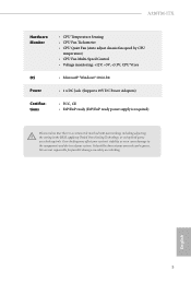
...; Supports Lightning/ESD Protection • Supports Energy Efficient Ethernet 802.3az • Supports PXE • 1 x DC Jack (Compatible with the 19V power adapter) • 1 x Serial Port: COM • 2 x HDMI Ports: HDMI1 (Rear), HDMI2 (Side) • 4 x USB 3.1 Gen1 Ports (Supports ESD Protection) • 1 x RJ-45 LAN Port with LED (ACT/LINK LED and SPEED LED) • HD Audio Jacks: Front Speaker / Microphone English 3 A320TM-ITX Audio LAN I/O • Dual graphics output: support HDMI and LVDS ports by independent display controllers • Supports 2 x HDMI 1.4 with max.
...; Supports Lightning/ESD Protection • Supports Energy Efficient Ethernet 802.3az • Supports PXE • 1 x DC Jack (Compatible with the 19V power adapter) • 1 x Serial Port: COM • 2 x HDMI Ports: HDMI1 (Rear), HDMI2 (Side) • 4 x USB 3.1 Gen1 Ports (Supports ESD Protection) • 1 x RJ-45 LAN Port with LED (ACT/LINK LED and SPEED LED) • HD Audio Jacks: Front Speaker / Microphone English 3 A320TM-ITX Audio LAN I/O • Dual graphics output: support HDMI and LVDS ports by independent display controllers • Supports 2 x HDMI 1.4 with max.

User Manual
Page 9
...Control Header • 1 x LVDS Connector • 2 x CPU Fan Connectors (4-pin) * The CPU Fan Connectors support the CPU fan of maximum 1A (12W) fan power. • 1 x 4 pin 19V Power Connector • 1 x Front Panel Audio Connector • 1 x Internal Speaker Header (4-Pin) • 1 x SATA Power Connector • 2 x USB 2.0 Headers (Support 4 USB 2.0 ports) (Supports ESD Protection) BIOS Feature • AMI UEFI Legal BIOS with GUI support • Supports "Plug and Play" • ACPI 5.1 compliance wake up events • Supports jumperfree • SMBIOS 2.3 support • CPU, DRAM...
...Control Header • 1 x LVDS Connector • 2 x CPU Fan Connectors (4-pin) * The CPU Fan Connectors support the CPU fan of maximum 1A (12W) fan power. • 1 x 4 pin 19V Power Connector • 1 x Front Panel Audio Connector • 1 x Internal Speaker Header (4-Pin) • 1 x SATA Power Connector • 2 x USB 2.0 Headers (Support 4 USB 2.0 ports) (Supports ESD Protection) BIOS Feature • AMI UEFI Legal BIOS with GUI support • Supports "Plug and Play" • ACPI 5.1 compliance wake up events • Supports jumperfree • SMBIOS 2.3 support • CPU, DRAM...
User Manual
Page 10
... CPU temperature) • CPU Fan Multi-Speed Control • Voltage monitoring: +12V, +5V, +3.3V, CPU Vcore • Microsoft® Windows® 10 64-bit • 1 x DC Jack (Supports 19V DC Power Adapters) • FCC, CE • ErP/EuP ready (ErP/EuP ready power supply is required) Please realize that there is a certain risk involved with overclocking, including adjusting the setting in the BIOS, applying Untied Overclocking Technology, or using third-party overclocking...
... CPU temperature) • CPU Fan Multi-Speed Control • Voltage monitoring: +12V, +5V, +3.3V, CPU Vcore • Microsoft® Windows® 10 64-bit • 1 x DC Jack (Supports 19V DC Power Adapters) • FCC, CE • ErP/EuP ready (ErP/EuP ready power supply is required) Please realize that there is a certain risk involved with overclocking, including adjusting the setting in the BIOS, applying Untied Overclocking Technology, or using third-party overclocking...
User Manual
Page 11
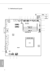
... 1 CLRCMOS1 1 1 1 USB_4_5 USB_6_7 1 BKT_PWR1 1 BLT_VOL1 11 1 1 PANEL_ DISABLE1 VCC_PWR_SEL M.2 SSD SATAPWR1 Ultra M.2 PCIe Gen3 x4 LVDS1 M.2 WiFi Plug DDR4_A2 First DDR4_A2 Short [Default] X O Open O (Priority) O entering OS) 10 11 12 DDR4_A1 A320TM-ITX 13 CPU_FAN1 Super I/O SOCKET AM4 17 USB 3.1 Gen1 T: USB0 B: USB1 Mic In Headphone RoHS 1 HD_AUDIO1 Audio CODEC SPK_OUT1 PANEL1 PLED PWRBTN 1 1 HDLED RESET CPU_FAN2 16 15 14 BIOS ROM English 6
... 1 CLRCMOS1 1 1 1 USB_4_5 USB_6_7 1 BKT_PWR1 1 BLT_VOL1 11 1 1 PANEL_ DISABLE1 VCC_PWR_SEL M.2 SSD SATAPWR1 Ultra M.2 PCIe Gen3 x4 LVDS1 M.2 WiFi Plug DDR4_A2 First DDR4_A2 Short [Default] X O Open O (Priority) O entering OS) 10 11 12 DDR4_A1 A320TM-ITX 13 CPU_FAN1 Super I/O SOCKET AM4 17 USB 3.1 Gen1 T: USB0 B: USB1 Mic In Headphone RoHS 1 HD_AUDIO1 Audio CODEC SPK_OUT1 PANEL1 PLED PWRBTN 1 1 HDLED RESET CPU_FAN2 16 15 14 BIOS ROM English 6

User Manual
Page 12
... CMOS Jumper (CLRCMOS1) 5 USB 3.0 Header (USB3_4_5) 6 USB 3.0 Header (USB3_6_7) 7 Backlight Power Jumper (BKT_PWR1) 8 Backlight Control Header (BLT_VOL1) Panel Disable Jumper (PANEL_DISABLE1) 12 9 Short [Default] Open Panel (LVDS) as video output X O (Priority) HDMI1 and HDMI2 as video output O O (After entering OS) 10 Panel Power Jumper (VCC_PWR_SEL) 11 LVDS Connector (LVDS1) 12 2 x 260-pin DDR4 SO-DIMM Slots (DDR4_A1, DDR4_A2) 13 CPU Fan Connector (CPU_FAN1) 14 CPU Fan Connector (CPU_FAN2) 15 System Panel Header (PANEL1) 16 Internal Speaker Header (SPK_OUT1) 17 Front Panel Audio...
... CMOS Jumper (CLRCMOS1) 5 USB 3.0 Header (USB3_4_5) 6 USB 3.0 Header (USB3_6_7) 7 Backlight Power Jumper (BKT_PWR1) 8 Backlight Control Header (BLT_VOL1) Panel Disable Jumper (PANEL_DISABLE1) 12 9 Short [Default] Open Panel (LVDS) as video output X O (Priority) HDMI1 and HDMI2 as video output O O (After entering OS) 10 Panel Power Jumper (VCC_PWR_SEL) 11 LVDS Connector (LVDS1) 12 2 x 260-pin DDR4 SO-DIMM Slots (DDR4_A1, DDR4_A2) 13 CPU Fan Connector (CPU_FAN1) 14 CPU Fan Connector (CPU_FAN2) 15 System Panel Header (PANEL1) 16 Internal Speaker Header (SPK_OUT1) 17 Front Panel Audio...

User Manual
Page 13
... Jack** 5 LAN RJ-45 Port* 2 HDMI Port (HDMI1) 6 USB 3.1 Gen1 Port (USB3_01) 3 COM Port 7 Microphone (Pink) 4 USB 3.1 Gen1 Port (USB3_23) 8 Front Speaker (Lime) *There are two LEDs on each LAN port. Doing so may damage the motherboard components and devices. 1.4 I/O Panel 1 2 3 4 5 4 78 No. Please do not use the onboard SATA power connector to the table below for the DC jack. When you use the DC-in power supplies. This jack accepts dual barrel plugs with an...
... Jack** 5 LAN RJ-45 Port* 2 HDMI Port (HDMI1) 6 USB 3.1 Gen1 Port (USB3_01) 3 COM Port 7 Microphone (Pink) 4 USB 3.1 Gen1 Port (USB3_23) 8 Front Speaker (Lime) *There are two LEDs on each LAN port. Doing so may damage the motherboard components and devices. 1.4 I/O Panel 1 2 3 4 5 4 78 No. Please do not use the onboard SATA power connector to the table below for the DC jack. When you use the DC-in power supplies. This jack accepts dual barrel plugs with an...
User Manual
Page 14
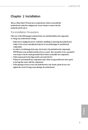
... removing the motherboard. Before you install the motherboard, study the configuration of the following precautions before you install motherboard components or change any components, place them on a carpet. Also remember to use a grounded wrist strap or touch a safety grounded object before you handle the components. • Hold components by the edges and do so may damage the motherboard. 9 English A320TM-ITX Chapter 2 Installation...
... removing the motherboard. Before you install the motherboard, study the configuration of the following precautions before you install motherboard components or change any components, place them on a carpet. Also remember to use a grounded wrist strap or touch a safety grounded object before you handle the components. • Hold components by the edges and do so may damage the motherboard. 9 English A320TM-ITX Chapter 2 Installation...

User Manual
Page 23
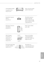
... the chassis to this header, make sure the wire assignments and the pin assignments are NOT jumpers. The LED is on when the hard drive is in S4 sleep state or powered off your chassis front panel module to this header according to the hard drive activity LED on the chassis front panel. A front panel module mainly consists of power button, reset button, power LED, hard drive activity LED, speaker and etc. Note the positive and negative pins before connecting the cables. The LED...
... the chassis to this header, make sure the wire assignments and the pin assignments are NOT jumpers. The LED is on when the hard drive is in S4 sleep state or powered off your chassis front panel module to this header according to the hard drive activity LED on the chassis front panel. A front panel module mainly consists of power button, reset button, power LED, hard drive activity LED, speaker and etc. Note the positive and negative pins before connecting the cables. The LED...
User Manual
Page 24
... p.6, No. 5) (9-pin USB_6_7) (see p.6, No. 6) USB_PWR PP+ GND DUMMY 1 GND P+ PUSB_PWR There are two headers on this header. MIC2_L 1 English 19 Serial ATA3 Connector (SATA_1: see p.6, No. 2) SATA Power Connector (SATAPWR1: see p.6, No. 3) SATA_1 1 +5V GND GND +12V This SATA3 connector supports SATA data cable for connecting audio devices to 6.0 Gb/ s data transfer rate. A320TM-ITX Internal Speaker Header (4-pin SPK_OUT1) (see p.6, No. 16) 1 R+ - - +L Please connect the chassis speaker to this motherboard. Each USB 2.0 header can support two ports.
... p.6, No. 5) (9-pin USB_6_7) (see p.6, No. 6) USB_PWR PP+ GND DUMMY 1 GND P+ PUSB_PWR There are two headers on this header. MIC2_L 1 English 19 Serial ATA3 Connector (SATA_1: see p.6, No. 2) SATA Power Connector (SATAPWR1: see p.6, No. 3) SATA_1 1 +5V GND GND +12V This SATA3 connector supports SATA data cable for connecting audio devices to 6.0 Gb/ s data transfer rate. A320TM-ITX Internal Speaker Header (4-pin SPK_OUT1) (see p.6, No. 16) 1 R+ - - +L Please connect the chassis speaker to this motherboard. Each USB 2.0 header can support two ports.

User Manual
Page 25
... panel audio header by the steps below: A. C. ATX 19V Power Connector +19V GND (4-pin ATX_PWR1 (see p.6, No. 1) Backlight Control Header 1 (8-pin BLT_VOL1) (see p.6, No. 14) 1 GND 2 FAN_VOLTAGE 3 CPU_FAN_SPEED 4 FAN_SPEED_CONTROL GND FAN_VOLTAGE FAN_SPEED FAN_SPEED_CONTROL 1 2 34 This motherboard provides two 4-Pin CPU fan (Quiet Fan) connectors. High Definition Audio supports Jack Sensing, but the panel wire on the chassis must support HDA to Ground (GND). You don't need to this GND connector. *The power supply plug fits into this connector...
... panel audio header by the steps below: A. C. ATX 19V Power Connector +19V GND (4-pin ATX_PWR1 (see p.6, No. 1) Backlight Control Header 1 (8-pin BLT_VOL1) (see p.6, No. 14) 1 GND 2 FAN_VOLTAGE 3 CPU_FAN_SPEED 4 FAN_SPEED_CONTROL GND FAN_VOLTAGE FAN_SPEED FAN_SPEED_CONTROL 1 2 34 This motherboard provides two 4-Pin CPU fan (Quiet Fan) connectors. High Definition Audio supports Jack Sensing, but the panel wire on the chassis must support HDA to Ground (GND). You don't need to this GND connector. *The power supply plug fits into this connector...

User Manual
Page 27
The M.2 Socket (Key E) supports type 2230 WiFi/BT module. A Step 3 Gently insert the WiFi/BT module into the M.2 slot. Please be used. A English A 20o 22 Installing the WiFi/BT module Step 1 Prepare a type 2230 WiFi/BT module and the screw. PCB Length: 3cm Module Type: Type2230 Step 2 Find the nut location to be aware that aims to replace mPCIe and mSATA. 2.6 M.2 WiFi/BT Module Installation Guide The M.2, also known as the Next Generation Form Factor (NGFF), is a small size and versatile card edge connector that the module only fits in one orientation.
The M.2 Socket (Key E) supports type 2230 WiFi/BT module. A Step 3 Gently insert the WiFi/BT module into the M.2 slot. Please be used. A English A 20o 22 Installing the WiFi/BT module Step 1 Prepare a type 2230 WiFi/BT module and the screw. PCB Length: 3cm Module Type: Type2230 Step 2 Find the nut location to be aware that aims to replace mPCIe and mSATA. 2.6 M.2 WiFi/BT Module Installation Guide The M.2, also known as the Next Generation Form Factor (NGFF), is a small size and versatile card edge connector that the module only fits in one orientation.

User Manual
Page 34
...-ROM drive. Click on the file "ASRSETUP.EXE" in your computer. Drivers Menu The drivers compatible to install it. 29 English Therefore, the drivers you install can work properly. Utilities Menu The Utilities Menu shows the application software that enhance the motherboard's features. The CD automatically displays the Main Menu if "AUTORUN" is enabled in the Support CD to install those required drivers. A320TM-ITX Chapter 3 Software and Utilities Operation 3.1 Installing Drivers The Support CD that comes with the motherboard contains necessary drivers...
...-ROM drive. Click on the file "ASRSETUP.EXE" in your computer. Drivers Menu The drivers compatible to install it. 29 English Therefore, the drivers you install can work properly. Utilities Menu The Utilities Menu shows the application software that enhance the motherboard's features. The CD automatically displays the Main Menu if "AUTORUN" is enabled in the Support CD to install those required drivers. A320TM-ITX Chapter 3 Software and Utilities Operation 3.1 Installing Drivers The Support CD that comes with the motherboard contains necessary drivers...

User Manual
Page 35
... system chassis. Because the UEFI software is constantly being updated, the following selections: Main For setting system time/date information OC Tweaker For overclocking configurations Advanced For advanced system configurations Tool Useful tools H/W Monitor Displays current hardware status Boot For configuring boot settings and boot priority Security For security settings Exit Exit the current screen or the UEFI Setup Utility English 30 Chapter 4 UEFI SETUP UTILITY 4.1 Introduction This section explains how to use the UEFI SETUP UTILITY to enter the UEFI SETUP UTILITY...
... system chassis. Because the UEFI software is constantly being updated, the following selections: Main For setting system time/date information OC Tweaker For overclocking configurations Advanced For advanced system configurations Tool Useful tools H/W Monitor Displays current hardware status Boot For configuring boot settings and boot priority Security For security settings Exit Exit the current screen or the UEFI Setup Utility English 30 Chapter 4 UEFI SETUP UTILITY 4.1 Introduction This section explains how to use the UEFI SETUP UTILITY to enter the UEFI SETUP UTILITY...
User Manual
Page 38
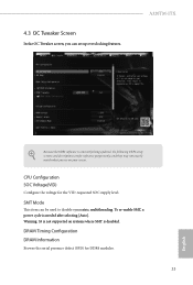
... after selecting [Auto]. Warning: S3 is not supported on your screen. A320TM-ITX Because the UEFI software is constantly being updated, the following UEFI setup screens and descriptions are for the VID-requested SOC supply level. CPU Configuration SOC Voltage(VID) Configure the voltage for reference purpose only, and they may not exactly match what you can be used to disable symmetric multithreading. DRAM Timing Configuration DRAM Information Browse the serial presence defect...
... after selecting [Auto]. Warning: S3 is not supported on your screen. A320TM-ITX Because the UEFI software is constantly being updated, the following UEFI setup screens and descriptions are for the VID-requested SOC supply level. CPU Configuration SOC Voltage(VID) Configure the voltage for reference purpose only, and they may not exactly match what you can be used to disable symmetric multithreading. DRAM Timing Configuration DRAM Information Browse the serial presence defect...

User Manual
Page 39
... default value is [Auto]. Save User UEFI Setup Profile to enable or disable performance mode The default value is selected, the motherboard will detect the memory module(s) inserted and assign the appropriate frequency automatically. The default value is [120W]. Performance Mode Use this to Disk Save current UEFI settings as user default. Load User Default Load previously saved user defaults. DRAM Frequency If [Auto] is [Disabled]. Voltage Configuration DRAM Voltage Use this to select DRAM Voltage. Adapter Select Use this to select the adapter. Save User Default Type...
... default value is [Auto]. Save User UEFI Setup Profile to enable or disable performance mode The default value is selected, the motherboard will detect the memory module(s) inserted and assign the appropriate frequency automatically. The default value is [120W]. Performance Mode Use this to Disk Save current UEFI settings as user default. Load User Default Load previously saved user defaults. DRAM Frequency If [Auto] is [Disabled]. Voltage Configuration DRAM Voltage Use this to select DRAM Voltage. Adapter Select Use this to select the adapter. Save User Default Type...

User Manual
Page 41
... enable or disable AMD's Cool 'n' QuietTM technology. Please note that enabling this item to system stability or compatibility issue with some memory modules or power supplies. SVM Mode When this item to [Enabled], a VMM (Virtual Machine Architecture) can utilize the additional hardware capabilities provided by AMD-V. The default value is set this function may reduce CPU voltage and memory frequency, and lead to [Enabled]. 4.4.1 CPU Configuration Cool 'n' Quiet Use this option is [Enabled]. The default value is [Enabled...
... enable or disable AMD's Cool 'n' QuietTM technology. Please note that enabling this item to system stability or compatibility issue with some memory modules or power supplies. SVM Mode When this item to [Enabled], a VMM (Virtual Machine Architecture) can utilize the additional hardware capabilities provided by AMD-V. The default value is set this function may reduce CPU voltage and memory frequency, and lead to [Enabled]. 4.4.1 CPU Configuration Cool 'n' Quiet Use this option is [Enabled]. The default value is [Enabled...

User Manual
Page 44
SATA Hot Plug Enable/disable the SATA Hot Plug Function. 39 English 4.4.4 Storage Configuration A320TM-ITX SATA Controller(s) Enable/disable the SATA controllers. SATA Mode AHCI: Supports new features that improve performance. RAID: Combine multiple disk drives into a logical unit.
SATA Hot Plug Enable/disable the SATA Hot Plug Function. 39 English 4.4.4 Storage Configuration A320TM-ITX SATA Controller(s) Enable/disable the SATA controllers. SATA Mode AHCI: Supports new features that improve performance. RAID: Combine multiple disk drives into a logical unit.
User Manual
Page 50
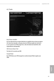
4.5 Tools A320TM-ITX Easy Driver Installer For users that don't have an optical disk drive to install the drivers from our support CD, Easy Driver Installer is a handy tool in your USB storage device and run Instant Flash to update your system via an USB storage device, then downloads and installs the other required drivers automatically. SSD Secure Erase Tool Use this tool to your UEFI. 45 English Instant Flash Save UEFI files in the UEFI that installs the LAN driver to securely erase SSD.
4.5 Tools A320TM-ITX Easy Driver Installer For users that don't have an optical disk drive to install the drivers from our support CD, Easy Driver Installer is a handy tool in your USB storage device and run Instant Flash to update your system via an USB storage device, then downloads and installs the other required drivers automatically. SSD Secure Erase Tool Use this tool to your UEFI. 45 English Instant Flash Save UEFI files in the UEFI that installs the LAN driver to securely erase SSD.


