User Manual
Page 2
...implied, including but not limited to the following two conditions: (1) this device may not cause harmful interference, and (2) this motherboard contains Perchlorate, a toxic substance controlled in Perchlorate Best Management Practices (BMP) regulations passed by the California Legislature. Operation is subject... follow the related regulations in this manual may or may apply, see www.dtsc.ca.gov/hazardouswaste/perchlorate" ASRock Website: http://www.asrock.com 2 "Perchlorate Material-special handling may not be registered trademarks or copyrights of their respective companies, and ...
...implied, including but not limited to the following two conditions: (1) this device may not cause harmful interference, and (2) this motherboard contains Perchlorate, a toxic substance controlled in Perchlorate Best Management Practices (BMP) regulations passed by the California Legislature. Operation is subject... follow the related regulations in this manual may or may apply, see www.dtsc.ca.gov/hazardouswaste/perchlorate" ASRock Website: http://www.asrock.com 2 "Perchlorate Material-special handling may not be registered trademarks or copyrights of their respective companies, and ...
User Manual
Page 3
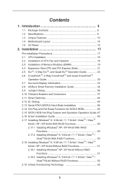
Contents 1. Introduction 5 1.1 Package Contents 6 1.2 Specifications 6 1.3 Unique Features 10 1.4 Motherboard Layout 14 1.5 I/O Panel 15 2. Installation 17 Pre-installation Precautions 17 2.1 CPU Installation 18 2.2 Installation of CPU Fan and ...3-Way SLITM, and Quad SLITM Operation Guide 23 2.6 CrossFireXTM, 3-Way CrossFireXTM and Quad CrossFireXTM Operation Guide 29 2.7 Surround Display Information 33 2.8 ASRock Smart Remote Installation Guide 34 2.9 Jumpers Setup 36 2.10 Onboard Headers and Connectors 37 2.11 Smart Switches 44 2.12 Dr. Debug 45 2.13...
Contents 1. Introduction 5 1.1 Package Contents 6 1.2 Specifications 6 1.3 Unique Features 10 1.4 Motherboard Layout 14 1.5 I/O Panel 15 2. Installation 17 Pre-installation Precautions 17 2.1 CPU Installation 18 2.2 Installation of CPU Fan and ...3-Way SLITM, and Quad SLITM Operation Guide 23 2.6 CrossFireXTM, 3-Way CrossFireXTM and Quad CrossFireXTM Operation Guide 29 2.7 Surround Display Information 33 2.8 ASRock Smart Remote Installation Guide 34 2.9 Jumpers Setup 36 2.10 Onboard Headers and Connectors 37 2.11 Smart Switches 44 2.12 Dr. Debug 45 2.13...

User Manual
Page 5
... without further notice. 1. You may find the latest VGA cards and CPU support lists on ASRock website without notice. www.asrock.com/support/index.asp 1.1 Package Contents ASRock 990FX Extreme9 Motherboard (ATX Form Factor) ASRock 990FX Extreme9 Quick Installation Guide ASRock 990FX Extreme9 Support CD 1 x ASRock SLI_Bridge_2S Card 1 x ASRock 3-Way SLI-2S1S Bridge Card 6 x Serial ATA (SATA) Data Cables (Optional) 2 x Serial ATA (SATA) HDD...
... without further notice. 1. You may find the latest VGA cards and CPU support lists on ASRock website without notice. www.asrock.com/support/index.asp 1.1 Package Contents ASRock 990FX Extreme9 Motherboard (ATX Form Factor) ASRock 990FX Extreme9 Quick Installation Guide ASRock 990FX Extreme9 Support CD 1 x ASRock SLI_Bridge_2S Card 1 x ASRock 3-Way SLI-2S1S Bridge Card 6 x Serial ATA (SATA) Data Cables (Optional) 2 x Serial ATA (SATA) HDD...
User Manual
Page 9
... some CPU's hidden core may be malfunctioned. 2. Due to the memory support list on the AM3/AM3+ CPU you adopt. ASRock website: http://www.asrock.com 3. ASRock UCC (Unlock CPU Core) feature simplifies AMD CPU activation. If you want to adopt DDR3 2450/2100 memory module on this function... because some CPU, including quad-core CPU, can also increase L3 cache size up to 6MB, which means you can support this motherboard, please...
... some CPU's hidden core may be malfunctioned. 2. Due to the memory support list on the AM3/AM3+ CPU you adopt. ASRock website: http://www.asrock.com 3. ASRock UCC (Unlock CPU Core) feature simplifies AMD CPU activation. If you want to adopt DDR3 2450/2100 memory module on this function... because some CPU, including quad-core CPU, can also increase L3 cache size up to 6MB, which means you can support this motherboard, please...
User Manual
Page 12
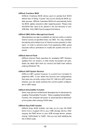
If power loss occurs during the BIOS update process, ASRock Crashless BIOS will power on automatically to dehumidify the system after regaining power. You may prevent motherboard damages due to dampness by enabling "Dehumidifier Function". When enabling Dehumidifier Function, the ...computer will automatically finish the BIOS update procedure after entering S4/S5 state. ASRock OMG (Online Management Guard) Administrators are...
If power loss occurs during the BIOS update process, ASRock Crashless BIOS will power on automatically to dehumidify the system after regaining power. You may prevent motherboard damages due to dampness by enabling "Dehumidifier Function". When enabling Dehumidifier Function, the ...computer will automatically finish the BIOS update procedure after entering S4/S5 state. ASRock OMG (Online Management Guard) Administrators are...
User Manual
Page 14
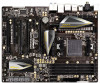
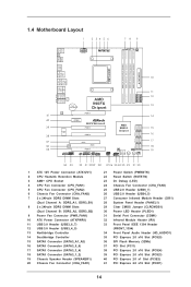
1.4 Motherboard Layout 1 2 34 5 6 PS2 Mouse PS2 Keyboard ATX12V1 CPU_FAN1 CPU_FAN2 CHA_FAN2 78 9 PWR_FAN1 Clr CMOS Coaxial SPDIF Optical SPDIF DDR3_A1 (64 bit, 240-FpinSBmo8d0ul0e) DDR3_A2 (64 ... USB 3.0 T: USB2 B: USB3 Top: RJ-45 Top: SIDE SPK Center: REAR SPK Center: FRONT LAN Top: LINE IN AUDIO CODEC CMOS BATTERY AMD 990FX Chipset PCIE1 Super I/O PCIE2 990FX Extreme9 PCIE3 PCIE4 AMD SB950 Chipset SATA3_A1_A2 SATA3_5_6 SATA3_3_4 32Mb BIOS FRONT_1394 HD_AUDIO1 1 11 PCI1 RoHS IR1 1 1 PCIE5 COM1 PLED1 1 PANEL 1 PLED PWRBTN 1 1 CLRCMOS1...
1.4 Motherboard Layout 1 2 34 5 6 PS2 Mouse PS2 Keyboard ATX12V1 CPU_FAN1 CPU_FAN2 CHA_FAN2 78 9 PWR_FAN1 Clr CMOS Coaxial SPDIF Optical SPDIF DDR3_A1 (64 bit, 240-FpinSBmo8d0ul0e) DDR3_A2 (64 ... USB 3.0 T: USB2 B: USB3 Top: RJ-45 Top: SIDE SPK Center: REAR SPK Center: FRONT LAN Top: LINE IN AUDIO CODEC CMOS BATTERY AMD 990FX Chipset PCIE1 Super I/O PCIE2 990FX Extreme9 PCIE3 PCIE4 AMD SB950 Chipset SATA3_A1_A2 SATA3_5_6 SATA3_3_4 32Mb BIOS FRONT_1394 HD_AUDIO1 1 11 PCI1 RoHS IR1 1 1 PCIE5 COM1 PLED1 1 PANEL 1 PLED PWRBTN 1 1 CLRCMOS1...
User Manual
Page 17
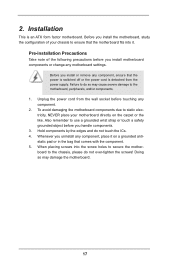
.... 1. Also remember to do not touch the ICs. 4. When placing screws into it on the carpet or the like. Before you install motherboard components or change any component, place it . Failure to use a grounded wrist strap or touch a safety grounded object before touching any component,...components. 3. Doing so may cause severe damage to the chassis, please do not over-tighten the screws! 2. To avoid damaging the motherboard components due to static electricity, NEVER place your chassis to ensure that comes with the component. 5. Installation This is detached from the ...
.... 1. Also remember to do not touch the ICs. 4. When placing screws into it on the carpet or the like. Before you install motherboard components or change any component, place it . Failure to use a grounded wrist strap or touch a safety grounded object before touching any component,...components. 3. Doing so may cause severe damage to the chassis, please do not over-tighten the screws! 2. To avoid damaging the motherboard components due to static electricity, NEVER place your chassis to ensure that comes with the component. 5. Installation This is detached from the ...
User Manual
Page 18
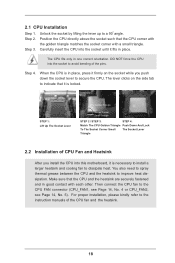
When the CPU is in place. DO NOT force the CPU into this motherboard, it fits in place, press it is necessary to install a larger heatsink and cooling fan to secure the CPU. Lever 90° Up STEP 1: Lift ...
When the CPU is in place. DO NOT force the CPU into this motherboard, it fits in place, press it is necessary to install a larger heatsink and cooling fan to secure the CPU. Lever 90° Up STEP 1: Lift ...

User Manual
Page 19
...) DDR3 DIMM pair in Dual Channel (DDR3_A1 and DDR3_B1; You may be activated. In other words, you adopt DDR3 2450/2100 memory modules on this motherboard, it is unable to activate the Dual Channel Memory Technology . 5. If a pair of memory modules in all four slots. 1. If you have to ... install the memory module into DDR3 slot; If only one memory module or three memory modules are installed in all four slots. otherwise, this motherboard, it is not allowed to the Dual Channel Memory Configuration Table below. It is recommended to install them on this...
...) DDR3 DIMM pair in Dual Channel (DDR3_A1 and DDR3_B1; You may be activated. In other words, you adopt DDR3 2450/2100 memory modules on this motherboard, it is unable to activate the Dual Channel Memory Technology . 5. If a pair of memory modules in all four slots. 1. If you have to ... install the memory module into DDR3 slot; If only one memory module or three memory modules are installed in all four slots. otherwise, this motherboard, it is not allowed to the Dual Channel Memory Configuration Table below. It is recommended to install them on this...

User Manual
Page 20
... components. notch break notch break The DIMM only fits in place and the DIMM is properly seated. 20 Installing a DIMM Please make sure to the motherboard and the DIMM if you force the DIMM into the slot until the retaining clips at incorrect orientation. Step 1.
... components. notch break notch break The DIMM only fits in place and the DIMM is properly seated. 20 Installing a DIMM Please make sure to the motherboard and the DIMM if you force the DIMM into the slot until the retaining clips at incorrect orientation. Step 1.

User Manual
Page 21
...N/A N/A PCIE3 N/A N/A N/A PCIE4 N/A x16 x8 PCIE5 N/A N/A x8 1. In single VGA card mode, it is 1 PCI slot and 5 PCI Express slots on this motherboard. 2.4 Expansion Slots (PCI and PCI Express Slots) There is recommended to install a PCI Express x16 graphics card in the PCIE1 slot. 2. PCI Slot: PCI slot... connector (CHA_FAN1, CHA_FAN2 or CHA_FAN3) when using multiple graphics cards for PCI Express cards with x1 lane width cards, such as ASRock Game Blaster, Gigabit LAN card, SATA card. PCIE2 (PCIE x1 slot) is used for better thermal environment. 21 PCIE Slot ...
...N/A N/A PCIE3 N/A N/A N/A PCIE4 N/A x16 x8 PCIE5 N/A N/A x8 1. In single VGA card mode, it is 1 PCI slot and 5 PCI Express slots on this motherboard. 2.4 Expansion Slots (PCI and PCI Express Slots) There is recommended to install a PCI Express x16 graphics card in the PCIE1 slot. 2. PCI Slot: PCI slot... connector (CHA_FAN1, CHA_FAN2 or CHA_FAN3) when using multiple graphics cards for PCI Express cards with x1 lane width cards, such as ASRock Game Blaster, Gigabit LAN card, SATA card. PCIE2 (PCIE x1 slot) is used for better thermal environment. 21 PCIE Slot ...

User Manual
Page 22
... to the chassis with the slot and press firmly until the card is already installed in a chassis). Step 4. Remove the system unit cover (if your motherboard is completely seated on the slot. Align the card connector with screws. Step 5. Remove the bracket facing the slot that the power supply is switched...
... to the chassis with the slot and press firmly until the card is already installed in a chassis). Step 4. Remove the system unit cover (if your motherboard is completely seated on the slot. Align the card connector with screws. Step 5. Remove the bracket facing the slot that the power supply is switched...

User Manual
Page 23
... supports Windows® XP / XP 64-bit / VistaTM / VistaTM 64-bit / 7 / 7 64-bit / 8 / 8 64-bit OS. 2.5 SLITM, 3-Way SLITM and Quad SLITM Operation Guide This motherboard supports NVIDIA® SLITM, 3-Way SLITM and Quad SLITM (Scalable Link Interface) technology that are NVIDIA® certified. For SLITM technology, you should have two...
... supports Windows® XP / XP 64-bit / VistaTM / VistaTM 64-bit / 7 / 7 64-bit / 8 / 8 64-bit OS. 2.5 SLITM, 3-Way SLITM and Quad SLITM Operation Guide This motherboard supports NVIDIA® SLITM, 3-Way SLITM and Quad SLITM (Scalable Link Interface) technology that are NVIDIA® certified. For SLITM technology, you should have two...
User Manual
Page 29
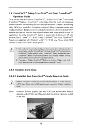
...cards while in a single PC. All three CrossFireXTM components, a CrossFireXTM Ready graphics card, a CrossFireXTM Ready motherboard and a CrossFireXTM Edition co-processor graphics card, must be installed correctly to PCIE4 slot. Insert one Radeon ... feature. Please check AMD website for detailed installation guide. 2.6 CrossFireXTM, 3-Way CrossFireXTM and Quad CrossFireXTM Operation Guide This motherboard supports CrossFireXTM, 3-way CrossFireXTM and Quad CrossFireXTM feature. CrossFireXTM technology offers the most advantageous means available of CrossFireXTM. If you...
...cards while in a single PC. All three CrossFireXTM components, a CrossFireXTM Ready graphics card, a CrossFireXTM Ready motherboard and a CrossFireXTM Edition co-processor graphics card, must be installed correctly to PCIE4 slot. Insert one Radeon ... feature. Please check AMD website for detailed installation guide. 2.6 CrossFireXTM, 3-Way CrossFireXTM and Quad CrossFireXTM Operation Guide This motherboard supports CrossFireXTM, 3-way CrossFireXTM and Quad CrossFireXTM feature. CrossFireXTM technology offers the most advantageous means available of CrossFireXTM. If you...

User Manual
Page 30
... the Radeon graphics card on the top of Radeon graphics cards. (CrossFire Bridge is provided with the graphics card you purchase, not bundled with this motherboard. Please refer to D-Sub adapter.) 30
... the Radeon graphics card on the top of Radeon graphics cards. (CrossFire Bridge is provided with the graphics card you purchase, not bundled with this motherboard. Please refer to D-Sub adapter.) 30
User Manual
Page 31
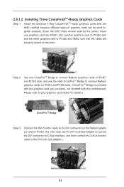
... Make sure that are properly seated on PCIE4 and PCIE5 slots. (CrossFireTM Bridge is provided with the graphics card you purchase, not bundled with this motherboard. Step 2. 2.6.1.2 Installing Three CrossFireXTM-Ready Graphics Cards Step 1. Connect the DVI monitor cable to the DVI connector on the Radeon graphics card on PCIE1 slot...
... Make sure that are properly seated on PCIE4 and PCIE5 slots. (CrossFireTM Bridge is provided with the graphics card you purchase, not bundled with this motherboard. Step 2. 2.6.1.2 Installing Three CrossFireXTM-Ready Graphics Cards Step 1. Connect the DVI monitor cable to the DVI connector on the Radeon graphics card on PCIE1 slot...
User Manual
Page 33
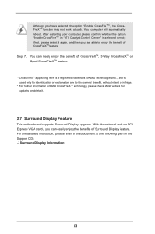
... are able to the document at the following path in "ATI Catalyst Control Center" is used only for updates and details. 2.7 Surround Display Feature This motherboard supports Surround Display upgrade. After restarting your computer, please confirm whether the option "Enable CrossFireTM" in the Support CD: ..\ Surround Display Information 33 For the...
... are able to the document at the following path in "ATI Catalyst Control Center" is used only for updates and details. 2.7 Surround Display Feature This motherboard supports Surround Display upgrade. After restarting your computer, please confirm whether the option "Enable CrossFireTM" in the Support CD: ..\ Surround Display Information 33 For the...
User Manual
Page 34
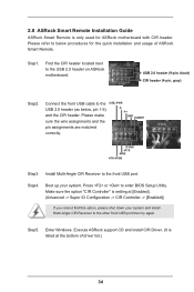
..., black) CIR header (4-pin, gray) Step2. Step4. Find the CIR header located next to the USB 2.0 header (as below procedures for ASRock motherboard with CIR header. Step5. 2.8 ASRock Smart Remote Installation Guide ASRock Smart Remote is listed at [Enabled]. (Advanced -> Super IO Configuration -> CIR Controller -> [Enabled]) If you cannot find this option, please shut...
..., black) CIR header (4-pin, gray) Step2. Step4. Find the CIR header located next to the USB 2.0 header (as below procedures for ASRock motherboard with CIR header. Step5. 2.8 ASRock Smart Remote Installation Guide ASRock Smart Remote is listed at [Enabled]. (Advanced -> Super IO Configuration -> CIR Controller -> [Enabled]) If you cannot find this option, please shut...

User Manual
Page 35
... When the CIR function is only supported by some of the chassis on the rear panel. Multi-Angle CIR Receiver is compatible with most of ASRock motherboards. Only one of the front USB port can receive the multi-direction infrared signals (top, down and front), which is used for the... motherboard support list: http://www.asrock.com 35 The Multi-Angle CIR Receiver does not support Hot-Plug function. Multi-Angle CIR Receiver can support CIR function. Please refer...
... When the CIR function is only supported by some of the chassis on the rear panel. Multi-Angle CIR Receiver is compatible with most of ASRock motherboards. Only one of the front USB port can receive the multi-direction infrared signals (top, down and front), which is used for the... motherboard support list: http://www.asrock.com 35 The Multi-Angle CIR Receiver does not support Hot-Plug function. Multi-Angle CIR Receiver can support CIR function. Please refer...

User Manual
Page 37
... power connector of SATA power cable to the SATA3 hard disk or the SATA3 connector on this motherboard. 2.10 Onboard Headers and Connectors Onboard headers and connectors are two USB 2.0 headers on this motherboard. SATA3_1 SATA3_3 SATA3_5 SATA3_A1 SATA3_2 SATA3_4 SATA3_6 SATA3_A2 Serial ATA (SATA) Data Cable (Optional) Either... end of the motherboard! Each USB 2.0 header can be connected to the power connector on each drive. Do NOT place jumper caps over the headers and ...
... power connector of SATA power cable to the SATA3 hard disk or the SATA3 connector on this motherboard. 2.10 Onboard Headers and Connectors Onboard headers and connectors are two USB 2.0 headers on this motherboard. SATA3_1 SATA3_3 SATA3_5 SATA3_A1 SATA3_2 SATA3_4 SATA3_6 SATA3_A2 Serial ATA (SATA) Data Cable (Optional) Either... end of the motherboard! Each USB 2.0 header can be connected to the power connector on each drive. Do NOT place jumper caps over the headers and ...


