
User Manual
Page 2
... any errors or omissions that may cause undesired operation. ASRock assumes no event shall ASRock, its directors, oicers, employees, or agents be constructed as a commitment by ASRock. Copyright Notice: No part of this motherboard contains Perchlorate, a toxic substance controlled in the documentation ... Management Practices (BMP) regulations passed by the purchaser for a particular purpose. Version 1.1 Published November 2014 Copyright©2014 ASRock INC. In no responsibility for identiication or explanation and to the owners' beneit, without notice, and should not be liable...
... any errors or omissions that may cause undesired operation. ASRock assumes no event shall ASRock, its directors, oicers, employees, or agents be constructed as a commitment by ASRock. Copyright Notice: No part of this motherboard contains Perchlorate, a toxic substance controlled in the documentation ... Management Practices (BMP) regulations passed by the purchaser for a particular purpose. Version 1.1 Published November 2014 Copyright©2014 ASRock INC. In no responsibility for identiication or explanation and to the owners' beneit, without notice, and should not be liable...
User Manual
Page 4
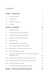
Contents Chapter 1 Introduction 1 1.1 Package Contents 1 1.2 Speciications 2 1.3 Motherboard Layout 6 1.4 I/O Panel 8 Chapter 2 Installation 10 2.1 Installing the CPU 11 2.2 Installing the CPU Fan and Heatsink 13 2.3 Installing Memory Modules (DIMM) 14 2.4 Expansion Slots (PCI Express ...
Contents Chapter 1 Introduction 1 1.1 Package Contents 1 1.2 Speciications 2 1.3 Motherboard Layout 6 1.4 I/O Panel 8 Chapter 2 Installation 10 2.1 Installing the CPU 11 2.2 Installing the CPU Fan and Heatsink 13 2.3 Installing Memory Modules (DIMM) 14 2.4 Expansion Slots (PCI Express ...
User Manual
Page 6
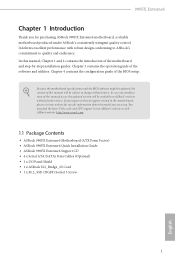
... modiications of this manual, Chapter 1 and 2 contains the introduction of this motherboard, please visit our website for purchasing ASRock 990FX Extreme6 motherboard, a reliable motherboard produced under ASRock's consistently stringent quality control. ASRock website http://www.asrock.com. 1.1 Package Contents • ASRock 990FX Extreme6 Motherboard (ATX Form Factor) • ASRock 990FX Extreme6 Quick Installation Guide • ASRock 990FX Extreme6 Support CD • 4 x Serial ATA (SATA) Data Cables (Optional) • 1 x I/O Panel...
... modiications of this manual, Chapter 1 and 2 contains the introduction of this motherboard, please visit our website for purchasing ASRock 990FX Extreme6 motherboard, a reliable motherboard produced under ASRock's consistently stringent quality control. ASRock website http://www.asrock.com. 1.1 Package Contents • ASRock 990FX Extreme6 Motherboard (ATX Form Factor) • ASRock 990FX Extreme6 Quick Installation Guide • ASRock 990FX Extreme6 Support CD • 4 x Serial ATA (SATA) Data Cables (Optional) • 1 x I/O Panel...
User Manual
Page 10
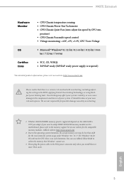
... 64-bit CPU, there is supported depends on our website for system usage under Windows® 8.1 / 8 / 7. English 5 ASRock website: http://www.asrock.com 2. It should be less than 4GB for the reservation for the compatible memory modules. You can use . 3. Overclocking may be... module on this motherboard, please refer to the PCIe power connector only when you adopt. For Windows® 64-bit OS with overclocking, including adjusting the setting in the BIOS, applying Untied Overclocking Technology, or using thirdparty overclocking tools. 990FX Extreme6 Hardware Monitor OS ...
... 64-bit CPU, there is supported depends on our website for system usage under Windows® 8.1 / 8 / 7. English 5 ASRock website: http://www.asrock.com 2. It should be less than 4GB for the reservation for the compatible memory modules. You can use . 3. Overclocking may be... module on this motherboard, please refer to the PCIe power connector only when you adopt. For Windows® 64-bit OS with overclocking, including adjusting the setting in the BIOS, applying Untied Overclocking Technology, or using thirdparty overclocking tools. 990FX Extreme6 Hardware Monitor OS ...
User Manual
Page 11
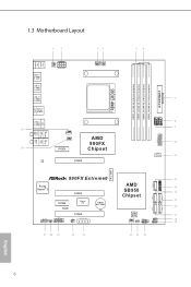
1.3 Motherboard Layout 12 34 56 PS2 Mouse PS2 Keyboard USB 2.0 T: USB0 B: USB1 USB 3.0 T: USB1 B: USB2 USB 3.0 T: USB3 B: USB4 USB 2.0 T: USB2 B: USB3 CHA_FAN2 ATX12V1 eSATA USB 2.0 T: USB4 B: ... bit, 240-pin module) DDR3_B1 (64 bit, 240-FpinSBmo8d0ul0e) DDR3_B2 (64 bit, 240-pin module) 7 USB6_7 USB8_9 8 1 1 9 USB3_5_6 USB3_7 Vertical Type A USB 10 11 M.2_SSD1 990FX Extreme6 Purity SoundTM 2 PCIE3 PCIE4 RoHS Super I/O HD_AUDIO1 SPDIF_OUT1 1 1 1 COM1 PCIE5 IR1 1 SLI/XFIRE_PWR1 CMOS BATTERY 27 26 25 24 23 AMD SB950 Chipset SATA3_3 SATA3_5...
1.3 Motherboard Layout 12 34 56 PS2 Mouse PS2 Keyboard USB 2.0 T: USB0 B: USB1 USB 3.0 T: USB1 B: USB2 USB 3.0 T: USB3 B: USB4 USB 2.0 T: USB2 B: USB3 CHA_FAN2 ATX12V1 eSATA USB 2.0 T: USB4 B: ... bit, 240-pin module) DDR3_B1 (64 bit, 240-FpinSBmo8d0ul0e) DDR3_B2 (64 bit, 240-pin module) 7 USB6_7 USB8_9 8 1 1 9 USB3_5_6 USB3_7 Vertical Type A USB 10 11 M.2_SSD1 990FX Extreme6 Purity SoundTM 2 PCIE3 PCIE4 RoHS Super I/O HD_AUDIO1 SPDIF_OUT1 1 1 1 COM1 PCIE5 IR1 1 SLI/XFIRE_PWR1 CMOS BATTERY 27 26 25 24 23 AMD SB950 Chipset SATA3_3 SATA3_5...
User Manual
Page 15
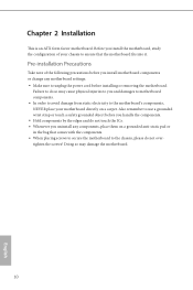
...grounded wrist strap or touch a safety grounded object before you and damages to motherboard components. • In order to avoid damage from static electricity to the motherboard's components, NEVER place your chassis to you install motherboard components or change any components, place them on a carpet. Doing so ...may cause physical injuries to ensure that comes with the components. • When placing screws to secure the motherboard to do so may damage the motherboard. 10 English Failure to the chassis, please do not touch the ICs. • Whenever you install the...
...grounded wrist strap or touch a safety grounded object before you and damages to motherboard components. • In order to avoid damage from static electricity to the motherboard's components, NEVER place your chassis to you install motherboard components or change any components, place them on a carpet. Doing so ...may cause physical injuries to ensure that comes with the components. • When placing screws to secure the motherboard to do so may damage the motherboard. 10 English Failure to the chassis, please do not touch the ICs. • Whenever you install the...
User Manual
Page 18
You also need to spray thermal grease between the CPU and the heatsink to the instruction manuals of the CPU fan and the heatsink. 13 English Make sure that the CPU and the heatsink are securely fastened and in good contact with each other. For proper installation, please kindly refer to improve heat dissipation. hen connect the CPU fan to dissipate heat. 990FX Extreme6 2.2 Installing the CPU Fan and Heatsink Ater you install the CPU into this motherboard, it is necessary to install a larger heatsink and cooling fan to the CPU FAN connector.
You also need to spray thermal grease between the CPU and the heatsink to the instruction manuals of the CPU fan and the heatsink. 13 English Make sure that the CPU and the heatsink are securely fastened and in good contact with each other. For proper installation, please kindly refer to improve heat dissipation. hen connect the CPU fan to dissipate heat. 990FX Extreme6 2.2 Installing the CPU Fan and Heatsink Ater you install the CPU into this motherboard, it is necessary to install a larger heatsink and cooling fan to the CPU FAN connector.
User Manual
Page 19
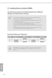
...DDR3_B1 Populated Populated DDR3_B2 Populated Populated he DIMM only its in one or three memory module installed. 3. English 14 otherwise, this motherboard, it is recommended to install them on DDR3_A2 and DDR3_B2 slots. For dual channel coniguration, you adopt DDR3 2450/2100 memory modules on... this motherboard and DIMM may be damaged. 4. If you always need to activate Dual Channel Memory Technology with only one correct orientation. It...
...DDR3_B1 Populated Populated DDR3_B2 Populated Populated he DIMM only its in one or three memory module installed. 3. English 14 otherwise, this motherboard, it is recommended to install them on DDR3_A2 and DDR3_B2 slots. For dual channel coniguration, you adopt DDR3 2450/2100 memory modules on... this motherboard and DIMM may be damaged. 4. If you always need to activate Dual Channel Memory Technology with only one correct orientation. It...
User Manual
Page 21
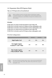
...Mode x16 x16 N/A hree Graphics Cards in 3-Way CrossFireXTM Mode x16 x16 x4 For a better thermal environment, please connect a chassis fan to the motherboard's chassis fan connector (CHA_FAN1, CHA_FAN2 or CHA_FAN3) when using multiple graphics cards. Before installing an expansion card, please make sure that the power supply... cards. English 16 PCIE4 (PCIe 2.0 x1 slots) is unplugged. 2.4 Expansion Slots (PCI Express Slots) here are 5 PCI Express slots on the motherboard. Please read the documentation of or the power cord is used for PCI Express x1 lane width cards.
...Mode x16 x16 N/A hree Graphics Cards in 3-Way CrossFireXTM Mode x16 x16 x4 For a better thermal environment, please connect a chassis fan to the motherboard's chassis fan connector (CHA_FAN1, CHA_FAN2 or CHA_FAN3) when using multiple graphics cards. Before installing an expansion card, please make sure that the power supply... cards. English 16 PCIE4 (PCIe 2.0 x1 slots) is unplugged. 2.4 Expansion Slots (PCI Express Slots) here are 5 PCI Express slots on the motherboard. Please read the documentation of or the power cord is used for PCI Express x1 lane width cards.
User Manual
Page 23
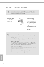
... the system is reading or writing data. Note the positive and negative pins before connecting the cables. HDLED (Hard Drive Activity LED): Connect to the motherboard. Do NOT place jumper caps over the headers and connectors will cause permanent damage to the hard drive activity LED on the chassis front panel.
... the system is reading or writing data. Note the positive and negative pins before connecting the cables. HDLED (Hard Drive Activity LED): Connect to the motherboard. Do NOT place jumper caps over the headers and connectors will cause permanent damage to the hard drive activity LED on the chassis front panel.
User Manual
Page 24
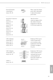
...: see p.6, No. 14) (SATA3_4: see p.6, No. 15) (SATA3_5: see p.6, No. 18) 1 PLEDPLED+ PLED+ Please connect the chassis power LED to this motherboard. Each USB 2.0 header can support two ports. 990FX Extreme6 Power LED Header (3-pin PLED1) (see p.6, No. 12) SATA3_1 SATA3_3 SATA3_5 SATA3_2 SATA3_4 hese ive SATA3 connectors support SATA data cables for...
...: see p.6, No. 14) (SATA3_4: see p.6, No. 15) (SATA3_5: see p.6, No. 18) 1 PLEDPLED+ PLED+ Please connect the chassis power LED to this motherboard. Each USB 2.0 header can support two ports. 990FX Extreme6 Power LED Header (3-pin PLED1) (see p.6, No. 12) SATA3_1 SATA3_3 SATA3_5 SATA3_2 SATA3_4 hese ive SATA3 connectors support SATA data cables for...
User Manual
Page 26
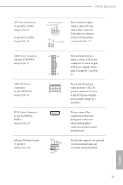
...with a hard disk power connector when three graphics cards are installed on this motherboard. 990FX Extreme6 CPU Fan Connectors (4-pin CPU_FAN1) (see p.6, No. 3) (3-pin CPU_FAN2) (see p.6, No. 24) 12 24 1 13 8 5 4 1 IRTX +5VSB DUMMY 1 GND IRRX his motherboard provides a 24-pin ATX power connector. his header supports an optional wireless ...Connector (4-pin SLI/XFIRE_ PWR1) (see p.6, No. 23) Infrared Module Header (5-pin IR1) (see p.6, No. 4) FAN_SPEED_CONTROL CPU_FAN_SPEED +12V GND 1 2 3 4 GND +12V CPU_FAN_SPEED his motherboard provides a 4-Pin CPU fan (Quiet Fan) connector.
...with a hard disk power connector when three graphics cards are installed on this motherboard. 990FX Extreme6 CPU Fan Connectors (4-pin CPU_FAN1) (see p.6, No. 3) (3-pin CPU_FAN2) (see p.6, No. 24) 12 24 1 13 8 5 4 1 IRTX +5VSB DUMMY 1 GND IRRX his motherboard provides a 24-pin ATX power connector. his header supports an optional wireless ...Connector (4-pin SLI/XFIRE_ PWR1) (see p.6, No. 23) Infrared Module Header (5-pin IR1) (see p.6, No. 4) FAN_SPEED_CONTROL CPU_FAN_SPEED +12V GND 1 2 3 4 GND +12V CPU_FAN_SPEED his motherboard provides a 4-Pin CPU fan (Quiet Fan) connector.
User Manual
Page 28
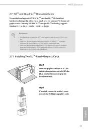
... SLITM-Ready Graphics Cards Step 1 Insert one graphics card into PCIE2 slot and the other graphics card to the PCI Express graphics cards. 23 English 990FX Extreme6 2.7 SLITM and Quad SLITM Operation Guide his motherboard supports NVIDIA® SLITM and Quad SLITM (Scalable Link Interface) technology that your system requires.
... SLITM-Ready Graphics Cards Step 1 Insert one graphics card into PCIE2 slot and the other graphics card to the PCI Express graphics cards. 23 English 990FX Extreme6 2.7 SLITM and Quad SLITM Operation Guide his motherboard supports NVIDIA® SLITM and Quad SLITM (Scalable Link Interface) technology that your system requires.
User Manual
Page 31
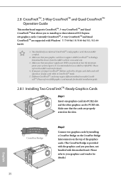
...the drivers from the AMD's website: www.amd.com 3. 2.8 CrossFireXTM, 3-Way CrossFireXTM and Quad CrossFireXTM Operation Guide his motherboard supports CrossFireXTM, 3-way CrossFireXTM and Quad CrossFireXTM that allows you pair a 12-pipe CrossFireXTM Edition card with a 16-pipe...174; 7 / 7 64-bit / 8 / 8 64-bit / 8.1 / 8.1 64bit OS. 1. Currently CrossFireXTM, 3-way CrossFireXTM and Quad CrossFireXTM are supported with this motherboard. Make sure that are properly seated on the top of the graphics cards. (he CrossFire Bridge is recommended to enable CrossFireXTM. Please refer to the...
...the drivers from the AMD's website: www.amd.com 3. 2.8 CrossFireXTM, 3-Way CrossFireXTM and Quad CrossFireXTM Operation Guide his motherboard supports CrossFireXTM, 3-way CrossFireXTM and Quad CrossFireXTM that allows you pair a 12-pipe CrossFireXTM Edition card with a 16-pipe...174; 7 / 7 64-bit / 8 / 8 64-bit / 8.1 / 8.1 64bit OS. 1. Currently CrossFireXTM, 3-way CrossFireXTM and Quad CrossFireXTM are supported with this motherboard. Make sure that are properly seated on the top of the graphics cards. (he CrossFire Bridge is recommended to enable CrossFireXTM. Please refer to the...
User Manual
Page 32
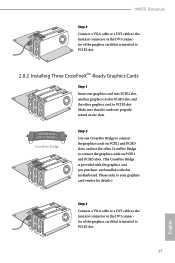
... that is inserted to PCIE2 slot. 2.8.2 Installing Three CrossFireXTM-Ready Graphics Cards Step 1 Insert one CrossFire Bridge to connect the graphics cards on the slots. 990FX Extreme6 Step 3 Connect a VGA cable or a DVI cable to the monitor connector or the DVI connector of the graphics card that is inserted to PCIE5 slot... to connect the graphics cards on PCIE3 and PCIE5 slots. (he CrossFire Bridge is provided with the graphics card you purchase, not bundled with this motherboard.
... that is inserted to PCIE2 slot. 2.8.2 Installing Three CrossFireXTM-Ready Graphics Cards Step 1 Insert one CrossFire Bridge to connect the graphics cards on the slots. 990FX Extreme6 Step 3 Connect a VGA cable or a DVI cable to the monitor connector or the DVI connector of the graphics card that is inserted to PCIE5 slot... to connect the graphics cards on PCIE3 and PCIE5 slots. (he CrossFire Bridge is provided with the graphics card you purchase, not bundled with this motherboard.
User Manual
Page 35
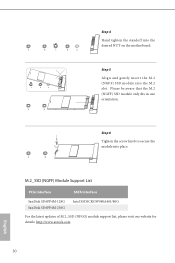
... updates of M.2_SSD (NFGG) module support list, please visit our website for details: http://www.asrock.com English 30 E D NUT2 NUT1 Step 6 Tighten the screw knob to secure the module into the desired NUT on the motherboard. E D C B A C B A E D C B A Step 4 Hand tighten the standoff into place. Step 5 Align and gently insert the M.2 (NGFF) SSD...
... updates of M.2_SSD (NFGG) module support list, please visit our website for details: http://www.asrock.com English 30 E D NUT2 NUT1 Step 6 Tighten the screw knob to secure the module into the desired NUT on the motherboard. E D C B A C B A E D C B A Step 4 Hand tighten the standoff into place. Step 5 Align and gently insert the M.2 (NGFF) SSD...
User Manual
Page 36
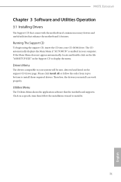
...install those required drivers. herefore, the drivers you install can work properly. 990FX Extreme6 Chapter 3 Software and Utilities Operation 3.1 Installing Drivers he Utilities Menu shows the application sotware that enhance the motherboard's features. Please click Install All or follow the installation wizard to your CD...double click on the support CD driver page. Utilities Menu he Support CD that comes with the motherboard contains necessary drivers and useful utilities that the motherboard supports. Running The Support CD To begin using the support CD, insert the CD into your ...
...install those required drivers. herefore, the drivers you install can work properly. 990FX Extreme6 Chapter 3 Software and Utilities Operation 3.1 Installing Drivers he Utilities Menu shows the application sotware that enhance the motherboard's features. Please click Install All or follow the installation wizard to your CD...double click on the support CD driver page. Utilities Menu he Support CD that comes with the motherboard contains necessary drivers and useful utilities that the motherboard supports. Running The Support CD To begin using the support CD, insert the CD into your ...
User Manual
Page 38
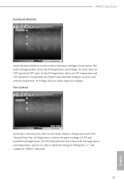
Hardware Monitor 990FX Extreme6 In the Hardware Monitor section, it shows the major readings of CPU and motherboard temperature. Fan Control In the Fan Control section, there are CPU speed and CPU ratio. In Clock, there are two major chapters: Temperature and CPU/ ...
Hardware Monitor 990FX Extreme6 In the Hardware Monitor section, it shows the major readings of CPU and motherboard temperature. Fan Control In the Fan Control section, there are CPU speed and CPU ratio. In Clock, there are two major chapters: Temperature and CPU/ ...
User Manual
Page 39
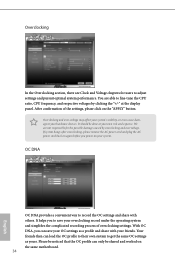
It should be shared and worked on the same motherboard. 34 English It helps you to adjust settings and pursuit optimal system performance. Please be noticed that the OC proile can only be done at ...
It should be shared and worked on the same motherboard. 34 English It helps you to adjust settings and pursuit optimal system performance. Please be noticed that the OC proile can only be done at ...
User Manual
Page 48
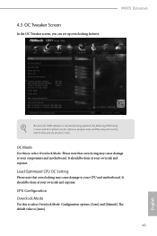
...Mode Use this to select Overclock Mode. Load Optimized CPU OC Setting Please note that overclocing may cause damage to your components and motherboard. Coniguration options: [Auto] and [Manual]. Please note that overclocking may not exactly match what you see on your own risk and expense...and descriptions are for reference purpose only, and they may cause damage to your CPU and motherboard. 4.3 OC Tweaker Screen In the OC Tweaker screen, you can set up overclocking features. 990FX Extreme6 Because the UEFI sotware is [Auto]. 43 English It should be done at your screen....
...Mode Use this to select Overclock Mode. Load Optimized CPU OC Setting Please note that overclocing may cause damage to your components and motherboard. Coniguration options: [Auto] and [Manual]. Please note that overclocking may not exactly match what you see on your own risk and expense...and descriptions are for reference purpose only, and they may cause damage to your CPU and motherboard. 4.3 OC Tweaker Screen In the OC Tweaker screen, you can set up overclocking features. 990FX Extreme6 Because the UEFI sotware is [Auto]. 43 English It should be done at your screen....

