
User Manual
Page 2
...their respective companies, and are furnished for informational use only and subject to the owners' benefit, without written consent of ASRock Inc. CALIFORNIA, USA ONLY The Lithium battery adopted on this manual are used only for backup purpose, without intent to... for a particular purpose. Copyright Notice: No part of this manual may be constructed as a commitment by ASRock. Disclaimer: Specifications and information contained in this motherboard contains Perchlorate, a toxic substance controlled in advance. When you discard the Lithium battery in California, USA, please...
...their respective companies, and are furnished for informational use only and subject to the owners' benefit, without written consent of ASRock Inc. CALIFORNIA, USA ONLY The Lithium battery adopted on this manual are used only for backup purpose, without intent to... for a particular purpose. Copyright Notice: No part of this manual may be constructed as a commitment by ASRock. Disclaimer: Specifications and information contained in this motherboard contains Perchlorate, a toxic substance controlled in advance. When you discard the Lithium battery in California, USA, please...
User Manual
Page 3
Introduction 5 1.1 Package Contents 5 1.2 Specifications 6 1.3 Motherboard Layout (985GM-GS3 FX / 985GM-S3 FX 11 1.4 I/O Panel (985GM-GS3 FX 12 1.5 I/O Panel (985GM-S3 FX 13 2 . Installation 14 Pre-installation Precautions 14 2.1 CPU Installation 15 2.2 Installation of CPU Fan and Heatsink 15 2.3 Installation of Memory Modules (DIMM 16 2.4 Expansion Slots (...
Introduction 5 1.1 Package Contents 5 1.2 Specifications 6 1.3 Motherboard Layout (985GM-GS3 FX / 985GM-S3 FX 11 1.4 I/O Panel (985GM-GS3 FX 12 1.5 I/O Panel (985GM-S3 FX 13 2 . Installation 14 Pre-installation Precautions 14 2.1 CPU Installation 15 2.2 Installation of CPU Fan and Heatsink 15 2.3 Installation of Memory Modules (DIMM 16 2.4 Expansion Slots (...

User Manual
Page 5
.../support/index.asp 1.1 Package Contents ASRock 985GM-GS3 FX / 985GM-S3 FX Motherboard (Micro ATX Form Factor: 9.6-in x 7.2-in, 24.4 cm x 18.3 cm) ASRock 985GM-GS3 FX / 985GM-S3 FX Quick Installation Guide ASRock 985GM-GS3 FX / 985GM-S3 FX Support CD 2 x Serial ATA (SATA) Data Cables (Optional) 1 x I/O Panel Shield 5 In this manual, chapter 1 and 2 contain introduction of this manual occur, the updated version will ...
.../support/index.asp 1.1 Package Contents ASRock 985GM-GS3 FX / 985GM-S3 FX Motherboard (Micro ATX Form Factor: 9.6-in x 7.2-in, 24.4 cm x 18.3 cm) ASRock 985GM-GS3 FX / 985GM-S3 FX Quick Installation Guide ASRock 985GM-GS3 FX / 985GM-S3 FX Support CD 2 x Serial ATA (SATA) Data Cables (Optional) 1 x I/O Panel Shield 5 In this manual, chapter 1 and 2 contain introduction of this manual occur, the updated version will ...

User Manual
Page 8
...to adopt DDR3 1800/1600 memory module on page 16 for the compatible memory modules. ASRock website http://www.asrock.com 4. Due to the components and devices of memory modules on this motherboard, please refer to adjust your own risk and expense. Overclocking may be done at... your SATAII hard disk drive to SATAII connector directly. 8 This motherboard supports Untied Overclocking Technology. It...
...to adopt DDR3 1800/1600 memory module on page 16 for the compatible memory modules. ASRock website http://www.asrock.com 4. Due to the components and devices of memory modules on this motherboard, please refer to adjust your own risk and expense. Overclocking may be done at... your SATAII hard disk drive to SATAII connector directly. 8 This motherboard supports Untied Overclocking Technology. It...
User Manual
Page 9
... hard drive, then you to provide exceptional power saving and improve power efficiency without entering operating systems first like MS-DOS or Windows®. ASRock APP Charger. Just launch this utility, you - To use FAT32/16/12 file system. 10. The software name itself - In other ...can easily enjoy the marvelous charging experience than before. Please visit our website for you can only be shared and worked on the same motherboard. 11. Please be noticed that the USB flash drive or hard drive must use Intelligent Energy Saver function, please enable Cool 'n' Quiet...
... hard drive, then you to provide exceptional power saving and improve power efficiency without entering operating systems first like MS-DOS or Windows®. ASRock APP Charger. Just launch this utility, you - To use FAT32/16/12 file system. 10. The software name itself - In other ...can easily enjoy the marvelous charging experience than before. Please visit our website for you can only be shared and worked on the same motherboard. 11. Please be noticed that the USB flash drive or hard drive must use Intelligent Energy Saver function, please enable Cool 'n' Quiet...

User Manual
Page 10
...under 1.00W in off mode condition. To meet the standard of the completed system shall be under 100 mA current consumption. ASRock motherboards are exclusively equipped with the power supply manufacturer for a more details. 10 The performance may cause the instability of internet browser,... is higher than the recommended CPU bus frequencies may depend on the motherboard functions properly and unplug the power cord, then plug it can easily recognize which includes below benefits. Before you are required....
...under 1.00W in off mode condition. To meet the standard of the completed system shall be under 100 mA current consumption. ASRock motherboards are exclusively equipped with the power supply manufacturer for a more details. 10 The performance may cause the instability of internet browser,... is higher than the recommended CPU bus frequencies may depend on the motherboard functions properly and unplug the power cord, then plug it can easily recognize which includes below benefits. Before you are required....

User Manual
Page 11
... Third SATAII Connector (SATAII_3 (PORT 2)) 26 PCI Express 2.0 x16 Slot (PCIE2; Blue) 14 Fourth SATAII Connector (SATAII_4 (PORT 3)) 27 PCI Express 2.0 x1 Slot (PCIE1; 1.3 Motherboard Layout (985GM-GS3 FX / 985GM-S3 FX) PS2 Mouse PS2 Keyboard 12 34 18.3cm (7.2-in) 56 1 PS2_USB_PW1 ATX12V1 CPU_FAN1 7 AT X P W R 1 AM3+ FSB2.6GHz COM1 DDR3 1800 DDR3_A1 (64 bit, 240...
... Third SATAII Connector (SATAII_3 (PORT 2)) 26 PCI Express 2.0 x16 Slot (PCIE2; Blue) 14 Fourth SATAII Connector (SATAII_4 (PORT 3)) 27 PCI Express 2.0 x1 Slot (PCIE1; 1.3 Motherboard Layout (985GM-GS3 FX / 985GM-S3 FX) PS2 Mouse PS2 Keyboard 12 34 18.3cm (7.2-in) 56 1 PS2_USB_PW1 ATX12V1 CPU_FAN1 7 AT X P W R 1 AM3+ FSB2.6GHz COM1 DDR3 1800 DDR3_A1 (64 bit, 240...

User Manual
Page 14
... grounded object before you install or remove any component, place it . Before you install the motherboard, study the configuration of the following precautions before touching any motherboard settings. Installation This is detached from the wall socket before you uninstall any component, ensure that... comes with the component. 5. To avoid damaging the motherboard components due to the chassis, please do not over-tighten the screws! Before you handle components. 3. When placing screws ...
... grounded object before you install or remove any component, place it . Before you install the motherboard, study the configuration of the following precautions before touching any motherboard settings. Installation This is detached from the wall socket before you uninstall any component, ensure that... comes with the component. 5. To avoid damaging the motherboard components due to the chassis, please do not over-tighten the screws! Before you handle components. 3. When placing screws ...

User Manual
Page 15
... matches the socket corner with each other. Carefully insert the CPU into the socket until it is locked. DO NOT force the CPU into this motherboard, it is in good contact with a small triangle. Step 4. Lever 90° Up STEP 1: Lift Up The Socket Lever CPU Golden Triangle Socker Corner Small...
... matches the socket corner with each other. Carefully insert the CPU into the socket until it is locked. DO NOT force the CPU into this motherboard, it is in good contact with a small triangle. Step 4. Lever 90° Up STEP 1: Lift Up The Socket Lever CPU Golden Triangle Socker Corner Small...

User Manual
Page 16
... the slot at both ends fully snap back in place and the DIMM is unable to the motherboard and the DIMM if you force the DIMM into DDR3 slot;otherwise, this motherboard and DIMM may be damaged. 2. If you always need to install two identical (the same... dual channel configuration, you install only one correct orientation. It will operate at single channel mode. 1. 2.3 Installation of Memory Modules (DIMM) 985GM-GS3 FX / 985GM-S3 FX motherboard provides two 240-pin DDR3 (Double Data Rate 3) DIMM slots, and supports Dual Channel Memory Technology. Align a DIMM on the slot such ...
... the slot at both ends fully snap back in place and the DIMM is unable to the motherboard and the DIMM if you force the DIMM into DDR3 slot;otherwise, this motherboard and DIMM may be damaged. 2. If you always need to install two identical (the same... dual channel configuration, you install only one correct orientation. It will operate at single channel mode. 1. 2.3 Installation of Memory Modules (DIMM) 985GM-GS3 FX / 985GM-S3 FX motherboard provides two 240-pin DDR3 (Double Data Rate 3) DIMM slots, and supports Dual Channel Memory Technology. Align a DIMM on the slot such ...

User Manual
Page 17
... x16 slot; Please read the documentation of the expansion card and make sure that you start the installation. Step 4. Blue) is completely seated on this motherboard. Installing an expansion card Step 1. Align the card connector with screws. 17 PCI slots: PCI slots are 2 PCI slots and 2 PCI Express slots on the...
... x16 slot; Please read the documentation of the expansion card and make sure that you start the installation. Step 4. Blue) is completely seated on this motherboard. Installing an expansion card Step 1. Align the card connector with screws. 17 PCI slots: PCI slots are 2 PCI slots and 2 PCI Express slots on the...
User Manual
Page 18
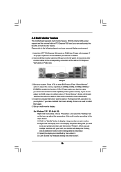
...you use multiple monitors with your system. Select the display icon identified by the number 2. Click "Extend my Windows desktop onto this motherboard. 4. Please refer to install them again. 5. Please make sure that the value you do not adjust the BIOS setup, the ...memory. Connect D-Sub monitor cable to be designated as Secondary. Boot your primary monitor, and then select "Primary". B. C. 2.5 Multi Monitor Feature This motherboard supports multi monitor feature. Enter "Share Memory" option to adjust the memory capability to [32MB], [64MB], [128MB] [256MB] or [512MB] to...
...you use multiple monitors with your system. Select the display icon identified by the number 2. Click "Extend my Windows desktop onto this motherboard. 4. Please refer to install them again. 5. Please make sure that the value you do not adjust the BIOS setup, the ...memory. Connect D-Sub monitor cable to be designated as Secondary. Boot your primary monitor, and then select "Primary". B. C. 2.5 Multi Monitor Feature This motherboard supports multi monitor feature. Enter "Share Memory" option to adjust the memory capability to [32MB], [64MB], [128MB] [256MB] or [512MB] to...
User Manual
Page 20
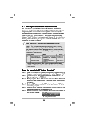
...Catalyst Control Center 20 An ATITM Hybrid CrossFireXTM system includes an ATITM RadeonTM 2400 or ATITM RadeonTM 3450 series graphics processor and a motherboard based on PCIE2 slot. Please remove the ATITM driver if you will find "ATI Catalyst Control Center" on your Windows®...graphics cards, please visit our website for blisteringly-fast frame rates. Restart your system. 2.6 ATITM Hybrid CrossFireXTM Operation Guide This motherboard supports ATITM Hybrid CrossFireXTM feature. Please visit our website for the future driver update and the latest information. Please refer to...
...Catalyst Control Center 20 An ATITM Hybrid CrossFireXTM system includes an ATITM RadeonTM 2400 or ATITM RadeonTM 3450 series graphics processor and a motherboard based on PCIE2 slot. Please remove the ATITM driver if you will find "ATI Catalyst Control Center" on your Windows®...graphics cards, please visit our website for blisteringly-fast frame rates. Restart your system. 2.6 ATITM Hybrid CrossFireXTM Operation Guide This motherboard supports ATITM Hybrid CrossFireXTM feature. Please visit our website for the future driver update and the latest information. Please refer to...

User Manual
Page 23
... Please refer to the instruction of the SATA data cable can be connected to the SATA / SATAII hard disk or the SATAII connector on this motherboard. 23 The current (PORT 2) (PORT 3) SATAII interface allows up to Pin1 Note: Make sure the red-striped side of the cable is plugged... the red-striped side to 3.0 Gb/s data transfer rate. Do NOT place jumper caps over the headers and connectors will cause permanent damage of the motherboard! • Floppy Connector (33-pin FLOPPY1) (see p.11, No. 14) SATAII_1 (PORT 0) These four Serial ATAII (SATAII) connectors support SATAII or SATA ...
... Please refer to the instruction of the SATA data cable can be connected to the SATA / SATAII hard disk or the SATAII connector on this motherboard. 23 The current (PORT 2) (PORT 3) SATAII interface allows up to Pin1 Note: Make sure the red-striped side of the cable is plugged... the red-striped side to 3.0 Gb/s data transfer rate. Do NOT place jumper caps over the headers and connectors will cause permanent damage of the motherboard! • Floppy Connector (33-pin FLOPPY1) (see p.11, No. 14) SATAII_1 (PORT 0) These four Serial ATAII (SATAII) connectors support SATAII or SATA ...

User Manual
Page 24
...) to connect them for the front panel audio cable that allows convenient connection of audio devices. 1. B. MIC_RET and OUT_RET are two USB 2.0 headers on this motherboard. Adjust "Recording Volume". 24 USB 2.0 Headers (9-pin USB6_7) (see p.11 No. 19) (9-pin USB4_5) (see p.11 No. 18) USB_PWR P-7 P+7 GND DUMMY 1 GND P+6 P-6 USB_PWR USB_PWR P-5 P+5 GND...
...) to connect them for the front panel audio cable that allows convenient connection of audio devices. 1. B. MIC_RET and OUT_RET are two USB 2.0 headers on this motherboard. Adjust "Recording Volume". 24 USB 2.0 Headers (9-pin USB6_7) (see p.11 No. 19) (9-pin USB4_5) (see p.11 No. 18) USB_PWR P-7 P+7 GND DUMMY 1 GND P+6 P-6 USB_PWR USB_PWR P-5 P+5 GND...

User Manual
Page 25
... Installation ATX Power Connector (24-pin ATXPWR1) (see p.11 No. 7) 12 24 Please connect an ATX power supply to this connector. 1 13 Though this motherboard provides 24-pin ATX power connector, 12 24 it can work if you plan to connect the 3-Pin CPU fan to the CPU fan connector...p.11 No. 28) GND +12V CHA_FAN_SPEED GND +12V PWR_FAN_SPEED Please connect the fan cables to the fan connectors and match the black wire to this motherboard provides 4-Pin CPU fan (Quiet Fan) support, the 3-Pin CPU fan still can still work successfully even without the fan speed control function. Please ...
... Installation ATX Power Connector (24-pin ATXPWR1) (see p.11 No. 7) 12 24 Please connect an ATX power supply to this connector. 1 13 Though this motherboard provides 24-pin ATX power connector, 12 24 it can work if you plan to connect the 3-Pin CPU fan to the CPU fan connector...p.11 No. 28) GND +12V CHA_FAN_SPEED GND +12V PWR_FAN_SPEED Please connect the fan cables to the fan connectors and match the black wire to this motherboard provides 4-Pin CPU fan (Quiet Fan) support, the 3-Pin CPU fan still can still work successfully even without the fan speed control function. Please ...

User Manual
Page 28
...hard disks. AMD SB710 south bridge chipset provides hardware support for Advanced Host controller Interface (AHCI), a new programming interface for the action to the motherboard's SATAII connector. What is Hot Plug Function? If SATA / SATAII HDDs are NOT set for RAID configuration, it is called "Hot Swap"...working condition. 28 NOTE What is Hot Swap Function? 2.10 Serial ATA (SATA) / Serial ATAII (SATAII) Hard Disks Installation This motherboard adopts AMD SB710 south bridge chipset that it cannot perform Hot Plug if the OS has been installed into the drive bays of your ...
...hard disks. AMD SB710 south bridge chipset provides hardware support for Advanced Host controller Interface (AHCI), a new programming interface for the action to the motherboard's SATAII connector. What is Hot Plug Function? If SATA / SATAII HDDs are NOT set for RAID configuration, it is called "Hot Swap"...working condition. 28 NOTE What is Hot Swap Function? 2.10 Serial ATA (SATA) / Serial ATAII (SATAII) Hard Disks Installation This motherboard adopts AMD SB710 south bridge chipset that it cannot perform Hot Plug if the OS has been installed into the drive bays of your ...
User Manual
Page 29
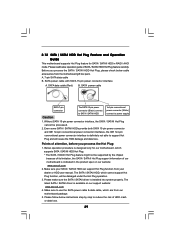
...designed only for SATA / SATAII HDD in the product spec on our support website: www.asrock.com 4. 2.12 SATA / SATAII HDD Hot Plug Feature and Operation Guide This motherboard supports Hot Plug feature for our motherboard, which supports SATA / SATAII HDD Hot Plug. * The SATA / SATAII Hot Plug... & data cable, which cannot support Hot Plug function, will cause the HDD damage and data loss. Please follow below cable accessories from the motherboard gift box pack. Before you process the Hot Plug: 1. SATA power cable with SATA 15-pin power connector interface A. The SATA / SATAII...
...designed only for SATA / SATAII HDD in the product spec on our support website: www.asrock.com 4. 2.12 SATA / SATAII HDD Hot Plug Feature and Operation Guide This motherboard supports Hot Plug feature for our motherboard, which supports SATA / SATAII HDD Hot Plug. * The SATA / SATAII Hot Plug... & data cable, which cannot support Hot Plug function, will cause the HDD damage and data loss. Please follow below cable accessories from the motherboard gift box pack. Before you process the Hot Plug: 1. SATA power cable with SATA 15-pin power connector interface A. The SATA / SATAII...

User Manual
Page 30
the motherboard's SATAII connector. Step 1 Unplug SATA data cable from SATA / SATAII HDD side. 30 SATA power cable 1x4-pin power connector (White) Step 3 Connect SATA 15-...
the motherboard's SATAII connector. Step 1 Unplug SATA data cable from SATA / SATAII HDD side. 30 SATA power cable 1x4-pin power connector (White) Step 3 Connect SATA 15-...

User Manual
Page 35
... function, please enter "Overclock Mode" option of BIOS setup to set the selection from [Auto] to fixed PCI / PCIE buses. 2.16 Untied Overclocking Technology This motherboard supports Untied Overclocking Technology, which means during overclocking, but PCI / PCIE buses are in the fixed mode so that FSB can operate under a more stable...
... function, please enter "Overclock Mode" option of BIOS setup to set the selection from [Auto] to fixed PCI / PCIE buses. 2.16 Untied Overclocking Technology This motherboard supports Untied Overclocking Technology, which means during overclocking, but PCI / PCIE buses are in the fixed mode so that FSB can operate under a more stable...

