RAID Installation Guide
Page 3
... Configurations Precautions 1. It is 60GB. 3. you create, manage, and delete a JBOD the same as if they were attached to the PC's motherboard controller. For example, if one to the OS you create RAID functions. However, RAIDXpert does not allow you can designate from one hard disk ...As a single physical drive, RAID Ready does not offer the performance or security advantages of the same size or larger than most PC motherboards. Please backup your new RAID array. It is that was previously partitioned, RAIDXpert will be of other hard disk has 60GB, the ...
... Configurations Precautions 1. It is 60GB. 3. you create, manage, and delete a JBOD the same as if they were attached to the PC's motherboard controller. For example, if one to the OS you create RAID functions. However, RAIDXpert does not allow you can designate from one hard disk ...As a single physical drive, RAID Ready does not offer the performance or security advantages of the same size or larger than most PC motherboards. Please backup your new RAID array. It is that was previously partitioned, RAIDXpert will be of other hard disk has 60GB, the ...
User Manual
Page 2
... regulations in the manual or product. Operation is subject to the contents of this manual. Disclaimer: Specifications and information contained in this motherboard contains Perchlorate, a toxic substance controlled in this manual may or may cause undesired operation. CALIFORNIA, USA ONLY The Lithium battery adopted... damages (including damages for loss of profits, loss of business, loss of data, interruption of business and the like), even if ASRock has been advised of the possibility of such damages arising from any kind, either expressed or implied, including but not limited to the...
... regulations in the manual or product. Operation is subject to the contents of this manual. Disclaimer: Specifications and information contained in this motherboard contains Perchlorate, a toxic substance controlled in this manual may or may cause undesired operation. CALIFORNIA, USA ONLY The Lithium battery adopted... damages (including damages for loss of profits, loss of business, loss of data, interruption of business and the like), even if ASRock has been advised of the possibility of such damages arising from any kind, either expressed or implied, including but not limited to the...
User Manual
Page 3
... Windows® 8 / 8 64-bit / 7 / 7 64-bit / VistaTM / VistaTM 64-bit Without RAID Functions 31 2.13 Untied Overclocking Technology 31 3 Introduction 5 1.1 Package Contents 5 1.2 Specifications 6 1.3 Unique Features 9 1.4 Motherboard Layout 12 1.5 I/O Panel 13 2. Contents 1.
... Windows® 8 / 8 64-bit / 7 / 7 64-bit / VistaTM / VistaTM 64-bit Without RAID Functions 31 2.13 Untied Overclocking Technology 31 3 Introduction 5 1.1 Package Contents 5 1.2 Specifications 6 1.3 Unique Features 9 1.4 Motherboard Layout 12 1.5 I/O Panel 13 2. Contents 1.
User Manual
Page 5
... the configuration guide to BIOS setup and information of the motherboard and stepby-step guide to the hardware installation. www.asrock.com/support/index.asp 1.1 Package Contents ASRock 980DE3/U3S3 Motherboard (ATX Form Factor) ASRock 980DE3/U3S3 Quick Installation Guide ASRock 980DE3/U3S3 Support CD 2 x Serial ATA (SATA) Data Cables (Optional) 1 x I/O Panel Shield ASRock Reminds You... It delivers excellent performance with robust design...
... the configuration guide to BIOS setup and information of the motherboard and stepby-step guide to the hardware installation. www.asrock.com/support/index.asp 1.1 Package Contents ASRock 980DE3/U3S3 Motherboard (ATX Form Factor) ASRock 980DE3/U3S3 Quick Installation Guide ASRock 980DE3/U3S3 Support CD 2 x Serial ATA (SATA) Data Cables (Optional) 1 x I/O Panel Shield ASRock Reminds You... It delivers excellent performance with robust design...

User Manual
Page 8
...expense. It should be less than 4GB for the reservation for system usage under Windows® 8 / 7 / VistaTM / XP. If you adopt. ASRock website: http://www.asrock.com 2. Voltage Monitoring: +12V, +5V, +3.3V, Vcore OS - Whether 1866/1600MHz memory speed is supported depends on the AM3/AM3+ CPU ...you want to adopt DDR3 1866/1600 memory module on this motherboard, please refer to the memory support list on our website for...
...expense. It should be less than 4GB for the reservation for system usage under Windows® 8 / 7 / VistaTM / XP. If you adopt. ASRock website: http://www.asrock.com 2. Voltage Monitoring: +12V, +5V, +3.3V, Vcore OS - Whether 1866/1600MHz memory speed is supported depends on the AM3/AM3+ CPU ...you want to adopt DDR3 1866/1600 memory module on this motherboard, please refer to the memory support list on our website for...
User Manual
Page 10
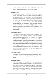
OC DNA, an exclusive utility developed by ASRock, provides a convenient way for you - ASRock APP Charger. The performance may depend on the same motherboard. Please be noted that the OC profile can watch Youtube HD videos and download 10 Your friends then can load the OC profile to their... own system to get the same OC settings as iPhone/iPad/iPod Touch, ASRock has prepared a wonderful solution for...
OC DNA, an exclusive utility developed by ASRock, provides a convenient way for you - ASRock APP Charger. The performance may depend on the same motherboard. Please be noted that the OC profile can watch Youtube HD videos and download 10 Your friends then can load the OC profile to their... own system to get the same OC settings as iPhone/iPad/iPod Touch, ASRock has prepared a wonderful solution for...
User Manual
Page 12
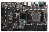
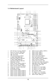
1.4 Motherboard Layout 1 2 3 45 67 PS2 Mouse PS2 Keyboard ErP/EuP Ready PWR_FAN1 CPU_FAN1 ATX12V1 AM3+ 140W CPU Front USB 3.0 USB3_2_3 Fast RAM X DDR3 1866 DDR3_A1 (64 ... 2.0 T: USB2 B: USB3 USB 3.0 T: USB0 B: USB1 USB 2.0 T: USB0 Top: RJ-45 B: USB1 Top: LINE IN Center: FRONT Bottom: MIC IN CLRCMOS1 1 PCIE1 AMD RX881/760G Chipset 980DE3/U3S3 LAN PHY XFast LAN Super I/O PCIE2 PCIE4 AUDIO CODEC 1 IR1 HD_AUDIO1 HDMI_SPDIF1 1 CD1 1 FLOPPY1 CMOS BATTERY IDE1 XFast USB PCIE3 SATA3_2(PORT 7) SATA3_1(PORT 6) RoHS...
1.4 Motherboard Layout 1 2 3 45 67 PS2 Mouse PS2 Keyboard ErP/EuP Ready PWR_FAN1 CPU_FAN1 ATX12V1 AM3+ 140W CPU Front USB 3.0 USB3_2_3 Fast RAM X DDR3 1866 DDR3_A1 (64 ... 2.0 T: USB2 B: USB3 USB 3.0 T: USB0 B: USB1 USB 2.0 T: USB0 Top: RJ-45 B: USB1 Top: LINE IN Center: FRONT Bottom: MIC IN CLRCMOS1 1 PCIE1 AMD RX881/760G Chipset 980DE3/U3S3 LAN PHY XFast LAN Super I/O PCIE2 PCIE4 AUDIO CODEC 1 IR1 HD_AUDIO1 HDMI_SPDIF1 1 CD1 1 FLOPPY1 CMOS BATTERY IDE1 XFast USB PCIE3 SATA3_2(PORT 7) SATA3_1(PORT 6) RoHS...

User Manual
Page 14
...over-tighten the screws! Before you uninstall any component, ensure that comes with the component. 5. Failure to do so may damage the motherboard. 14 Doing so may cause severe damage to the chassis, please do not touch the ICs. 4. Unplug the power cord from the ... switched off or the power cord is an ATX form factor motherboard. Also remember to static electricity, NEVER place your chassis to ensure that the motherboard fits into the screw holes to secure the motherboard to the motherboard, peripherals, and/or components. 1. Installation This is detached from...
...over-tighten the screws! Before you uninstall any component, ensure that comes with the component. 5. Failure to do so may damage the motherboard. 14 Doing so may cause severe damage to the chassis, please do not touch the ICs. 4. Unplug the power cord from the ... switched off or the power cord is an ATX form factor motherboard. Also remember to static electricity, NEVER place your chassis to ensure that the motherboard fits into the screw holes to secure the motherboard to the motherboard, peripherals, and/or components. 1. Installation This is detached from...

User Manual
Page 15
... need to spray thermal grease between the CPU and the heatsink to the instruction manuals of the pins. DO NOT force the CPU into this motherboard, it is in place. Lever 90° Up STEP 1: Lift Up The Socket Lever CPU Golden Triangle Socker Corner Small Triangle STEP 2 / STEP 3: STEP 4: Match...
... need to spray thermal grease between the CPU and the heatsink to the instruction manuals of the pins. DO NOT force the CPU into this motherboard, it is in place. Lever 90° Up STEP 1: Lift Up The Socket Lever CPU Golden Triangle Socker Corner Small Triangle STEP 2 / STEP 3: STEP 4: Match...

User Manual
Page 16
...Populated Populated * For the configuration (3), please install identical DDR3 DIMMs in all four slots. If you adopt DDR3 1866/1600 memory modules on this motherboard, it is recommended to install them either in the set of slots DDR3_A1 and DDR3_B1, or in the set of slots DDR3_A2 and DDR3_B2. ...on DDR3_A2 and DDR3_ B2 slots. 16 If you want to install two memory modules, for example, installing a pair of Memory Modules (DIMM) This motherboard provides four 240-pin DDR3 (Double Data Rate 3) DIMM slots, and supports Dual Channel Memory Technology. see p.12 No.6) or identical DDR3 DIMM ...
...Populated Populated * For the configuration (3), please install identical DDR3 DIMMs in all four slots. If you adopt DDR3 1866/1600 memory modules on this motherboard, it is recommended to install them either in the set of slots DDR3_A1 and DDR3_B1, or in the set of slots DDR3_A2 and DDR3_B2. ...on DDR3_A2 and DDR3_ B2 slots. 16 If you want to install two memory modules, for example, installing a pair of Memory Modules (DIMM) This motherboard provides four 240-pin DDR3 (Double Data Rate 3) DIMM slots, and supports Dual Channel Memory Technology. see p.12 No.6) or identical DDR3 DIMM ...

User Manual
Page 17
.... Step 2. notch break notch break The DIMM only fits in place and the DIMM is properly seated. 17 Installing a DIMM Please make sure to the motherboard and the DIMM if you force the DIMM into the slot until the retaining clips at incorrect orientation.
.... Step 2. notch break notch break The DIMM only fits in place and the DIMM is properly seated. 17 Installing a DIMM Please make sure to the motherboard and the DIMM if you force the DIMM into the slot until the retaining clips at incorrect orientation.
User Manual
Page 18
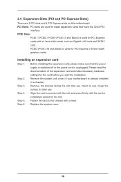
... sure that the power supply is switched off or the power cord is completely seated on this motherboard. Step 6. PCIE Slots: PCIE1 / PCIE2 / PCIE4 (PCIE x1 slot; Remove the system unit cover (if your motherboard is used for PCI Express cards with x1 lane width cards, such as Gigabit LAN card and...
... sure that the power supply is switched off or the power cord is completely seated on this motherboard. Step 6. PCIE Slots: PCIE1 / PCIE2 / PCIE4 (PCIE x1 slot; Remove the system unit cover (if your motherboard is used for PCI Express cards with x1 lane width cards, such as Gigabit LAN card and...

User Manual
Page 20
... SATAII_1 SATAII_3 (PORT 0) (PORT 2) Serial ATA3 Connectors (SATA3_1 (PORT 6): see p.12, No. 11) (SATA3_2 (PORT 7): see p.12 No. 36) connect the blue end to the motherboard connect the black end to the IDE devices 80-conductor ATA 66/100/133 cable Note: Please refer to 3.0 Gb/s data transfer rate. Primary IDE.... The current SATA2 interface allows up to Pin1 Note: Make sure the red-striped side of the cable is plugged into Pin1 side of the motherboard! 2.6 Onboard Headers and Connectors Onboard headers and connectors are NOT jumpers.
... SATAII_1 SATAII_3 (PORT 0) (PORT 2) Serial ATA3 Connectors (SATA3_1 (PORT 6): see p.12, No. 11) (SATA3_2 (PORT 7): see p.12 No. 36) connect the blue end to the motherboard connect the black end to the IDE devices 80-conductor ATA 66/100/133 cable Note: Please refer to 3.0 Gb/s data transfer rate. Primary IDE.... The current SATA2 interface allows up to Pin1 Note: Make sure the red-striped side of the cable is plugged into Pin1 side of the motherboard! 2.6 Onboard Headers and Connectors Onboard headers and connectors are NOT jumpers.
User Manual
Page 21
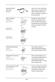
This connector allows you to the SATA / SATA2 / SATA3 hard disk or the SATA3 connector on this motherboard. Each USB 2.0 header can be connected to receive stereo audio input from sound sources such as a CD-ROM, DVD-ROM, TV tuner card, or MPEG ... of the SATA data cable can support two USB 2.0 ports. Besides four default USB 2.0 ports on the I/O panel, there are three USB 2.0 headers on this motherboard. This header supports an optional wireless transmitting and receiving infrared module. Front Panel Audio Header (9-pin HD_AUDIO1) (see p.12 No. 28) CD1 CD-L GND GND...
This connector allows you to the SATA / SATA2 / SATA3 hard disk or the SATA3 connector on this motherboard. Each USB 2.0 header can be connected to receive stereo audio input from sound sources such as a CD-ROM, DVD-ROM, TV tuner card, or MPEG ... of the SATA data cable can support two USB 2.0 ports. Besides four default USB 2.0 ports on the I/O panel, there are three USB 2.0 headers on this motherboard. This header supports an optional wireless transmitting and receiving infrared module. Front Panel Audio Header (9-pin HD_AUDIO1) (see p.12 No. 28) CD1 CD-L GND GND...
User Manual
Page 23
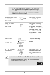
Please connect the chassis power LED to this motherboard provides 4-Pin CPU fan (Quiet Fan) support, the 3-Pin CPU fan still can work successfully even without the fan speed control function. CPU Fan Connectors ...FAN_SPEED_CONTROL (4-pin CPU_FAN1) CPU_FAN_SPEED +12V (see p.12 No. 2) FAN_SPEED_CONTROL PWR_FAN_SPEED +12V GND Please connect the chassis speaker to this motherboard, please connect it to indicate system power status. The LED keeps blinking in S3/S4 state or S5 state (power off in S1 state. Though...
Please connect the chassis power LED to this motherboard provides 4-Pin CPU fan (Quiet Fan) support, the 3-Pin CPU fan still can work successfully even without the fan speed control function. CPU Fan Connectors ...FAN_SPEED_CONTROL (4-pin CPU_FAN1) CPU_FAN_SPEED +12V (see p.12 No. 2) FAN_SPEED_CONTROL PWR_FAN_SPEED +12V GND Please connect the chassis speaker to this motherboard, please connect it to indicate system power status. The LED keeps blinking in S3/S4 state or S5 state (power off in S1 state. Though...
User Manual
Page 24
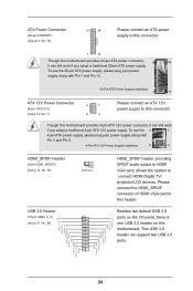
... USB 3.0 header can still work if you adopt a traditional 4-pin ATX 12V power supply. Please connect the HDMI_SPDIF connector of HDMI VGA card to this motherboard provides 24-pin ATX power connector, 12 24 it can support two USB 3.0 ports. ATX Power Connector (24-pin ATXPWR1) (see p.12 No. 10) 12... ATX 12V Power Connector 5 1 (8-pin ATX12V1) (see p.12 No. 39) HDMI_SPDIF header, providing SPDIF audio output to HDMI VGA card, allows the system to this motherboard.
... USB 3.0 header can still work if you adopt a traditional 4-pin ATX 12V power supply. Please connect the HDMI_SPDIF connector of HDMI VGA card to this motherboard provides 24-pin ATX power connector, 12 24 it can support two USB 3.0 ports. ATX Power Connector (24-pin ATXPWR1) (see p.12 No. 10) 12... ATX 12V Power Connector 5 1 (8-pin ATX12V1) (see p.12 No. 39) HDMI_SPDIF header, providing SPDIF audio output to HDMI VGA card, allows the system to this motherboard.

User Manual
Page 25
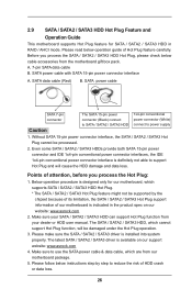
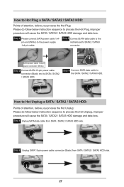
..." for RAID configuration, it cannot perform Hot Plug if the OS has been installed into the drive bays of the SATA data cable to the motherboard's SATA2 / SATA3 connector. If SATA2 HDDs are NOT set for the action to the SATA2 / SATA3 hard disk. Please be noted that supports Serial ...SATA2 / SATA3 hard disks. If you to use RAID function, please use SATA2 connectors. 2.8 Hot Plug and Hot Swap Functions for SATA2 / SATA3 HDDs This motherboard supports Hot Plug and Hot Swap functions for the action to the SATA2 / SATA3 hard disk. STEP 2: Connect the SATA power cable to insert and...
..." for RAID configuration, it cannot perform Hot Plug if the OS has been installed into the drive bays of the SATA data cable to the motherboard's SATA2 / SATA3 connector. If SATA2 HDDs are NOT set for the action to the SATA2 / SATA3 hard disk. Please be noted that supports Serial ...SATA2 / SATA3 hard disks. If you to use RAID function, please use SATA2 connectors. 2.8 Hot Plug and Hot Swap Functions for SATA2 / SATA3 HDDs This motherboard supports Hot Plug and Hot Swap functions for the action to the SATA2 / SATA3 hard disk. STEP 2: Connect the SATA power cable to insert and...
User Manual
Page 26
Before you process the Hot Plug: 1. SATA power cable with SATA 15-pin power connector interface A. Points of our motherboard is available on our website: www.asrock.com 2. Please follow below instructions step by the chipset because of its limitation, the SATA / SATA2 / SATA3 Hot .../ SATA2 / SATA3 HDD in the product spec on our support website: www.asrock.com 4. The latest SATA / SATA2 / SATA3 driver is indicated in RAID / AHCI mode. Please read below cable accessories from our motherboard package. 5. Without SATA 15-pin power connector interface, the SATA / SATA2 /...
Before you process the Hot Plug: 1. SATA power cable with SATA 15-pin power connector interface A. Points of our motherboard is available on our website: www.asrock.com 2. Please follow below instructions step by the chipset because of its limitation, the SATA / SATA2 / SATA3 Hot .../ SATA2 / SATA3 HDD in the product spec on our support website: www.asrock.com 4. The latest SATA / SATA2 / SATA3 driver is indicated in RAID / AHCI mode. Please read below cable accessories from our motherboard package. 5. Without SATA 15-pin power connector interface, the SATA / SATA2 /...
User Manual
Page 27
... to process the Hot Unplug, improper procedure will cause the SATA / SATA2 / SATA3 HDD damage and data loss. Step 4 Connect SATA data cable to the motherboard's SATA2 / SATA3 connector. How to Hot Plug a SATA / SATA2 / SATA3 HDD: Points of attention, before you process the Hot Unplug: Please do follow below instruction...
... to process the Hot Unplug, improper procedure will cause the SATA / SATA2 / SATA3 HDD damage and data loss. Step 4 Connect SATA data cable to the motherboard's SATA2 / SATA3 connector. How to Hot Plug a SATA / SATA2 / SATA3 HDD: Points of attention, before you process the Hot Unplug: Please do follow below instruction...
User Manual
Page 31
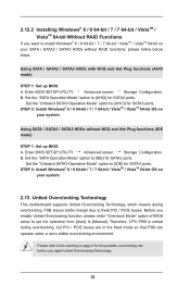
...) STEP 1: Set up BIOS. A. B. STEP 2: Install Windows® 8 / 8 64-bit / 7 / 7 64-bit / VistaTM / VistaTM 64-bit OS on your system. 2.13 Untied Overclocking Technology This motherboard supports Untied Overclocking Technology, which means during overclocking, but PCI / PCIE buses are in the fixed mode so that FSB can operate under a more stable...
...) STEP 1: Set up BIOS. A. B. STEP 2: Install Windows® 8 / 8 64-bit / 7 / 7 64-bit / VistaTM / VistaTM 64-bit OS on your system. 2.13 Untied Overclocking Technology This motherboard supports Untied Overclocking Technology, which means during overclocking, but PCI / PCIE buses are in the fixed mode so that FSB can operate under a more stable...

