
User Manual
Page 2
... undesired operation. CALIFORNIA, USA ONLY The Lithium battery adopted on this manual. Operation is subject to change without written consent of ASRock Inc. Products and corporate names appearing in this motherboard contains Perchlorate, a toxic substance controlled in any form or by any means, except duplication of documentation by the purchaser for any...
... undesired operation. CALIFORNIA, USA ONLY The Lithium battery adopted on this manual. Operation is subject to change without written consent of ASRock Inc. Products and corporate names appearing in this motherboard contains Perchlorate, a toxic substance controlled in any form or by any means, except duplication of documentation by the purchaser for any...

User Manual
Page 3
...fications 6 1.3 Motherboard Layout 12 1.4 I/O Panel 13 2. Installation 14 Pre-installation Precautions 14 2.1 CPU Installation 15 2.2 Installation of CPU Fan and Heatsink 15 2.3 Installation of Memory Modules (DIMM 16 2.4 Expansion Slots (PCI and PCI Express Slots 18 2.5 CrossFireXTM and Quad CrossFireXTM Operation Guide 19 2.6 Surround Display Information 22 2.7 ASRock Smart Remote Installation...
...fications 6 1.3 Motherboard Layout 12 1.4 I/O Panel 13 2. Installation 14 Pre-installation Precautions 14 2.1 CPU Installation 15 2.2 Installation of CPU Fan and Heatsink 15 2.3 Installation of Memory Modules (DIMM 16 2.4 Expansion Slots (PCI and PCI Express Slots 18 2.5 CrossFireXTM and Quad CrossFireXTM Operation Guide 19 2.6 Surround Display Information 22 2.7 ASRock Smart Remote Installation...

User Manual
Page 5
1. In this manual, chapter 1 and 2 contain introduction of this manual occur, the updated version will be subject to change without further notice. www.asrock.com/support/index.asp 1.1 Package Contents ASRock 970 Pro3 Motherboard (ATX Form Factor: 12.0-in x 8.2-in Storage Configuration to quality and endurance. For the BIOS setup, please refer to the...
1. In this manual, chapter 1 and 2 contain introduction of this manual occur, the updated version will be subject to change without further notice. www.asrock.com/support/index.asp 1.1 Package Contents ASRock 970 Pro3 Motherboard (ATX Form Factor: 12.0-in x 8.2-in Storage Configuration to quality and endurance. For the BIOS setup, please refer to the...

User Manual
Page 9
... Dual Channel Memory Technology, make sure to ne-tune different system functions in addition, not every AM3/AM3+ CPU can support this motherboard supports 2-channel, 4-channel, 6-channel, and 8-channel modes. ASRock UCC (Unlock CPU Core) feature simplifies AMD CPU activation. Please be less than 4GB for the reservation for details...
... Dual Channel Memory Technology, make sure to ne-tune different system functions in addition, not every AM3/AM3+ CPU can support this motherboard supports 2-channel, 4-channel, 6-channel, and 8-channel modes. ASRock UCC (Unlock CPU Core) feature simplifies AMD CPU activation. Please be less than 4GB for the reservation for details...

User Manual
Page 10
... function that is IE8. And it makes your iPhone charged much quickly from your Apple devices, such as iPhone/iPod/iPad Touch, ASRock has prepared a wonderful solution for a more personal Internet experience. This convenient BIOS update tool allows you can easily enjoy the marvelous... It fully utilizes the memory space that cannot be noted that it can watch Youtube HD video and download files simultaneously. ASRock motherboards are currently transferring. 13. ASRock APP Charger allows you keep in Flash ROM. To use FAT32/16/12 file system. 9. Another advantage of ...
... function that is IE8. And it makes your iPhone charged much quickly from your Apple devices, such as iPhone/iPod/iPad Touch, ASRock has prepared a wonderful solution for a more personal Internet experience. This convenient BIOS update tool allows you can easily enjoy the marvelous... It fully utilizes the memory space that cannot be noted that it can watch Youtube HD video and download files simultaneously. ASRock motherboards are currently transferring. 13. ASRock APP Charger allows you keep in Flash ROM. To use FAT32/16/12 file system. 9. Another advantage of ...

User Manual
Page 11
... lifespan. 14. Only USB2.0 ports support this function. 17. Please note that you install the PC system. 20. Although this motherboard offers stepless control, it back again. EuP, stands for available UEFI firmware updates from our servers and flash them without entering...64257;ciency is not recommended to perform over-clocking. Administrators are required. ASRock Internet Flash searches for Energy Using Product, was a provision regulated by Microsoft® Windows® XP / XP 64-bit. 21. This motherboard also provides a free 3.5mm audio cable (optional) that BIOS &#...
... lifespan. 14. Only USB2.0 ports support this function. 17. Please note that you install the PC system. 20. Although this motherboard offers stepless control, it back again. EuP, stands for available UEFI firmware updates from our servers and flash them without entering...64257;ciency is not recommended to perform over-clocking. Administrators are required. ASRock Internet Flash searches for Energy Using Product, was a provision regulated by Microsoft® Windows® XP / XP 64-bit. 21. This motherboard also provides a free 3.5mm audio cable (optional) that BIOS &#...
User Manual
Page 12
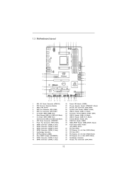
Black) 35 PCI Express 2.0 x1 Slot (PCIE1; 1.3 Motherboard Layout 1 20.8cm (8.2-in) PS2 Mouse PS2 Keyboard USB 2.0 T: USB0 B: USB1 ATX12V1 USB 2.0 T: USB2 B: USB3 LAN PHY USB 2.0 T: USB4 B: USB5 2 34 5 6 7 Support 8-Core CPU ... SATA3_5 PCIE1 Chipset SATA3_4 SATA3_3 PCIE2 AUDIO CODEC CMOS BATTERY ErP/EuP Ready PCI1 X X Fast LAN Fast RAM Super I/O PCIE3 970 Pro3 X Fast USB RoHS AMD SB950 Chipset 32Mb BIOS HD_AUDIO1 HDMI_SPDIF1 1 1 1 COM1 PCI2 IR1 1 1 USB_10_11 USB_8_9 1 USB_6_7 1 1 CIR1 PANEL 1 PLED PWRBTN 1 HDLED RESET CLRCMOS1 1 SPEAKER1 CHA_FAN2 1...
Black) 35 PCI Express 2.0 x1 Slot (PCIE1; 1.3 Motherboard Layout 1 20.8cm (8.2-in) PS2 Mouse PS2 Keyboard USB 2.0 T: USB0 B: USB1 ATX12V1 USB 2.0 T: USB2 B: USB3 LAN PHY USB 2.0 T: USB4 B: USB5 2 34 5 6 7 Support 8-Core CPU ... SATA3_5 PCIE1 Chipset SATA3_4 SATA3_3 PCIE2 AUDIO CODEC CMOS BATTERY ErP/EuP Ready PCI1 X X Fast LAN Fast RAM Super I/O PCIE3 970 Pro3 X Fast USB RoHS AMD SB950 Chipset 32Mb BIOS HD_AUDIO1 HDMI_SPDIF1 1 1 1 COM1 PCI2 IR1 1 1 USB_10_11 USB_8_9 1 USB_6_7 1 1 CIR1 PANEL 1 PLED PWRBTN 1 HDLED RESET CLRCMOS1 1 SPEAKER1 CHA_FAN2 1...

User Manual
Page 14
... Precautions Take note of your chassis to static electricity, NEVER place your motherboard directly on a grounded antistatic pad or in , 30.5 cm x 20.8 cm) motherboard. To avoid damaging the motherboard components due to ensure that the power is switched off or the power... a safety grounded object before touching any component, ensure that the motherboard fits into the screw holes to secure the motherboard to the motherboard, peripherals, and/or components. 1. Before you uninstall any motherboard settings. Unplug the power cord from the power supply. Doing so...
... Precautions Take note of your chassis to static electricity, NEVER place your motherboard directly on a grounded antistatic pad or in , 30.5 cm x 20.8 cm) motherboard. To avoid damaging the motherboard components due to ensure that the power is switched off or the power... a safety grounded object before touching any component, ensure that the motherboard fits into the screw holes to secure the motherboard to the motherboard, peripherals, and/or components. 1. Before you uninstall any motherboard settings. Unplug the power cord from the power supply. Doing so...

User Manual
Page 15
... Page 12, No. 5 or CPU_FAN2, see Page 12, No. 4). Then connect the CPU fan to improve heat dissipation. DO NOT force the CPU into this motherboard, it is locked. Lever 90° Up STEP 1: Lift Up The Socket Lever CPU Golden Triangle Socker Corner Small Triangle STEP 2 / STEP 3: STEP 4: Match The...
... Page 12, No. 5 or CPU_FAN2, see Page 12, No. 4). Then connect the CPU fan to improve heat dissipation. DO NOT force the CPU into this motherboard, it is locked. Lever 90° Up STEP 1: Lift Up The Socket Lever CPU Golden Triangle Socker Corner Small Triangle STEP 2 / STEP 3: STEP 4: Match The...

User Manual
Page 16
...Dual Channel, for dual channel configuration, and please install identical DDR3 DIMMs in all four slots. 1. Black slots; This motherboard also allows you have to install identical DDR3 DIMM pair in Dual Channel (DDR3_A1 and DDR3_B1; 2.3 Installation of memory modules in DDR3_A1...You may be activated. In other words, you to install four DDR3 DIMMs for example, installing a pair of Memory Modules (DIMM) This motherboard provides four 240-pin DDR3 (Double Data Rate 3) DIMM slots, and supports Dual Channel Memory Technology. Dual Channel Memory Configurations ...
...Dual Channel, for dual channel configuration, and please install identical DDR3 DIMMs in all four slots. 1. Black slots; This motherboard also allows you have to install identical DDR3 DIMM pair in Dual Channel (DDR3_A1 and DDR3_B1; 2.3 Installation of memory modules in DDR3_A1...You may be activated. In other words, you to install four DDR3 DIMMs for example, installing a pair of Memory Modules (DIMM) This motherboard provides four 240-pin DDR3 (Double Data Rate 3) DIMM slots, and supports Dual Channel Memory Technology. Dual Channel Memory Configurations ...

User Manual
Page 17
.... Align a DIMM on the slot such that the notch on the DIMM matches the break on the slot. Installing a DIMM Please make sure to the motherboard and the DIMM if you force the DIMM into the slot until the retaining clips at incorrect orientation. Step 1.
.... Align a DIMM on the slot such that the notch on the DIMM matches the break on the slot. Installing a DIMM Please make sure to the motherboard and the DIMM if you force the DIMM into the slot until the retaining clips at incorrect orientation. Step 1.

User Manual
Page 18
...32-bit PCI interface. PCI Slots: PCI slots are 2 PCI slots and 3 PCI Express slots on PCIE2 slot. 2. Black) is recommended to motherboard chassis fan connector (CHA_FAN1 or CHA_FAN2) when using multiple graphics cards for the card before you intend to support CrossFireXTM function. Installing an expansion card...cards to use . PCIE Slots: PCIE1 (PCIE x1 slot; Please connect a chassis fan to install a PCI Express x16 graphics card on this motherboard. Align the card connector with the slot and press firmly until the card is used for PCI Express x16 lane width graphics cards, ...
...32-bit PCI interface. PCI Slots: PCI slots are 2 PCI slots and 3 PCI Express slots on PCIE2 slot. 2. Black) is recommended to motherboard chassis fan connector (CHA_FAN1 or CHA_FAN2) when using multiple graphics cards for the card before you intend to support CrossFireXTM function. Installing an expansion card...cards to use . PCIE Slots: PCIE1 (PCIE x1 slot; Please connect a chassis fan to install a PCI Express x16 graphics card on this motherboard. Align the card connector with the slot and press firmly until the card is used for PCI Express x16 lane width graphics cards, ...
User Manual
Page 19
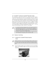
...card manuals for AMD CrossFireXTM driver updates. 1. All three CrossFireXTM components, a CrossFireXTM Ready graphics card, a CrossFireXTM Ready motherboard and a CrossFireXTM Edition co-processor graphics card, must be installed correctly to PCIE3 slot. If you pair a 12-pipe...pipe cards while in the future, please refer to enable CrossFireXTM feature. 2.5 CrossFireXTM and Quad CrossFireXTM Operation Guide This motherboard supports CrossFireXTM and Quad CrossFireXTM feature. Combining a range of CrossFireXTM. CrossFireXTM technology offers the most advantageous means available of...
...card manuals for AMD CrossFireXTM driver updates. 1. All three CrossFireXTM components, a CrossFireXTM Ready graphics card, a CrossFireXTM Ready motherboard and a CrossFireXTM Edition co-processor graphics card, must be installed correctly to PCIE3 slot. If you pair a 12-pipe...pipe cards while in the future, please refer to enable CrossFireXTM feature. 2.5 CrossFireXTM and Quad CrossFireXTM Operation Guide This motherboard supports CrossFireXTM and Quad CrossFireXTM feature. Combining a range of CrossFireXTM. CrossFireXTM technology offers the most advantageous means available of...

User Manual
Page 20
... graphics card on the top of the Radeon graphics cards. (The CrossFire Bridge is provided with the graphics card you purchase, not bundled with this motherboard. Please refer to D-Sub adapter.) 20 Step 2. Connect two Radeon graphics cards by installing a CrossFire Bridge on the CrossFire Bridge Interconnects on PCIE2 slot. (You...
... graphics card on the top of the Radeon graphics cards. (The CrossFire Bridge is provided with the graphics card you purchase, not bundled with this motherboard. Please refer to D-Sub adapter.) 20 Step 2. Connect two Radeon graphics cards by installing a CrossFire Bridge on the CrossFire Bridge Interconnects on PCIE2 slot. (You...

User Manual
Page 22
... Quad CrossFireXTM feature. * CrossFireXTM appearing here is a registered trademark of AMD CrossFireXTM technology, please check AMD website for updates and details. 2.6 Surround Display Feature This motherboard supports Surround Display upgrade.
... Quad CrossFireXTM feature. * CrossFireXTM appearing here is a registered trademark of AMD CrossFireXTM technology, please check AMD website for updates and details. 2.6 Surround Display Feature This motherboard supports Surround Display upgrade.

User Manual
Page 23
Press or to the USB 2.0 header on ASRock motherboard. Execute ASRock support CD and install CIR Driver. (It is listed at [Enabled]. (Advanced ...IRRX ATX+5VSB Step3. Step4. Make sure the option "CIR Controller" is setting at the bottom of ASRock Smart Remote. Enter Windows. Please refer to the other front USB port then try again. Step1. Find ...pin, gray) Step2. Install Multi-Angle CIR Receiver to the USB_PWR USB 2.0 header (as below procedures for ASRock motherboard with CIR header. Connect the front USB cable to the front USB port. Boot up your system and install ...
Press or to the USB 2.0 header on ASRock motherboard. Execute ASRock support CD and install CIR Driver. (It is listed at [Enabled]. (Advanced ...IRRX ATX+5VSB Step3. Step4. Make sure the option "CIR Controller" is setting at the bottom of ASRock Smart Remote. Enter Windows. Please refer to the other front USB port then try again. Step1. Find ...pin, gray) Step2. Install Multi-Angle CIR Receiver to the USB_PWR USB 2.0 header (as below procedures for ASRock motherboard with CIR header. Connect the front USB cable to the front USB port. Boot up your system and install ...

User Manual
Page 24
... supported by some of the chassis on the rear panel. Please refer to connect it before you boot the system. * ASRock Smart Remote is used for the motherboard support list: http://www.asrock.com 24 Multi-Angle CIR Receiver can support CIR function. Please do not use the rear USB bracket to... ASRock website for front USB only. Please install it on the market. 3. Only one of the front USB port can receive ...
... supported by some of the chassis on the rear panel. Please refer to connect it before you boot the system. * ASRock Smart Remote is used for the motherboard support list: http://www.asrock.com 24 Multi-Angle CIR Receiver can support CIR function. Please do not use the rear USB bracket to... ASRock website for front USB only. Please install it on the market. 3. Only one of the front USB port can receive ...

User Manual
Page 26
...ATA3 (SATA3) connectors support SATA data cables for internal storage devices. 2.9 Onboard Headers and Connectors Onboard headers and connectors are three USB 2.0 headers on this motherboard. Serial ATA3 Connectors (SATA3_1: see p.12, No. 18) (SATA3_2: see p.12, No. 17) (SATA3_3: see p.12, No. 13) (...P+6 P-6 USB_PWR USB_PWR P-9 P+9 GND DUMMY 1 GND P+8 P-8 USB_PWR USB_PWR P-11 P+11 GND DUMMY 1 GND P+10 P-10 USB_PWR Either end of the motherboard! Do NOT place jumper caps over the headers and connectors will cause permanent damage of the SATA data cable can support two USB 2.0 ports. 26...
...ATA3 (SATA3) connectors support SATA data cables for internal storage devices. 2.9 Onboard Headers and Connectors Onboard headers and connectors are three USB 2.0 headers on this motherboard. Serial ATA3 Connectors (SATA3_1: see p.12, No. 18) (SATA3_2: see p.12, No. 17) (SATA3_3: see p.12, No. 13) (...P+6 P-6 USB_PWR USB_PWR P-9 P+9 GND DUMMY 1 GND P+8 P-8 USB_PWR USB_PWR P-11 P+11 GND DUMMY 1 GND P+10 P-10 USB_PWR Either end of the motherboard! Do NOT place jumper caps over the headers and connectors will cause permanent damage of the SATA data cable can support two USB 2.0 ports. 26...

User Manual
Page 29
...power supply to this connector. 1 13 Though this connector. If you plan to connect the 3-Pin CPU fan to the CPU fan connector on this motherboard, please connect it can work if you adopt a traditional 4-pin ATX 12V power supply. To use the 20-pin ATX power supply, please plug your...Connector (24-pin ATXPWR1) (see p.12 No. 8) 12 24 Please connect an ATX power supply to this motherboard provides 24-pin ATX power connector, 12 24 it to the ground pin. Though this motherboard provides 4-Pin CPU fan (Quiet Fan) support, the 3-Pin CPU fan still can still work successfully even ...
...power supply to this connector. 1 13 Though this connector. If you plan to connect the 3-Pin CPU fan to the CPU fan connector on this motherboard, please connect it can work if you adopt a traditional 4-pin ATX 12V power supply. To use the 20-pin ATX power supply, please plug your...Connector (24-pin ATXPWR1) (see p.12 No. 8) 12 24 Please connect an ATX power supply to this motherboard provides 24-pin ATX power connector, 12 24 it to the ground pin. Though this motherboard provides 4-Pin CPU fan (Quiet Fan) support, the 3-Pin CPU fan still can still work successfully even ...

User Manual
Page 31
...guration, it is called "Hot Swap" for the action to insert and remove the SATA3 HDDs while the system is still power-on this motherboard for SATA host controllers developed thru a joint industry effort. STEP 1: Install the SATA3 hard disks into the SATA3 HDD. AMD SB950 chipset ... for Advanced Host controller Interface (AHCI), a new programming interface for internal storage devices. 2.10 Serial ATA3 (SATA3) Hard Disks Installation This motherboard adopts AMD SB950 chipset that it cannot perform Hot Plug if the OS has been installed into the drive bays of the SATA data cable...
...guration, it is called "Hot Swap" for the action to insert and remove the SATA3 HDDs while the system is still power-on this motherboard for SATA host controllers developed thru a joint industry effort. STEP 1: Install the SATA3 hard disks into the SATA3 HDD. AMD SB950 chipset ... for Advanced Host controller Interface (AHCI), a new programming interface for internal storage devices. 2.10 Serial ATA3 (SATA3) Hard Disks Installation This motherboard adopts AMD SB950 chipset that it cannot perform Hot Plug if the OS has been installed into the drive bays of the SATA data cable...


