RAID Installation Guide
Page 3
... storage capacity and the other RAID logical drives. Please use two SATA drives of the same size or larger than most PC motherboards. For example, if one to the PC's motherboard controller. If you are creating a RAID 0 (striping) array for this RAID 0 set is that was previously partitioned, RAIDXpert will be the...
... storage capacity and the other RAID logical drives. Please use two SATA drives of the same size or larger than most PC motherboards. For example, if one to the PC's motherboard controller. If you are creating a RAID 0 (striping) array for this RAID 0 set is that was previously partitioned, RAIDXpert will be the...

User Manual
Page 2
...damages (including damages for loss of profits, loss of business, loss of data, interruption of business and the like), even if ASRock has been advised of the possibility of such damages arising from any defect or error in this manual are used only for any errors... regulations in any form or by ASRock. CALIFORNIA, USA ONLY The Lithium battery adopted on this manual, ASRock does not provide warranty of any means, except duplication of documentation by the California Legislature. With respect to the contents of this motherboard contains Perchlorate, a toxic substance controlled...
...damages (including damages for loss of profits, loss of business, loss of data, interruption of business and the like), even if ASRock has been advised of the possibility of such damages arising from any defect or error in this manual are used only for any errors... regulations in any form or by ASRock. CALIFORNIA, USA ONLY The Lithium battery adopted on this manual, ASRock does not provide warranty of any means, except duplication of documentation by the California Legislature. With respect to the contents of this motherboard contains Perchlorate, a toxic substance controlled...

User Manual
Page 3
... 2.12.2 Installing Windows® 7 / 7 64-bit / VistaTM / VistaTM 64-bit Without RAID Functions 31 2.13 Untied Overclocking Technology 31 3 Introduction 5 1.1 Package Contents 5 1.2 Specifications 6 1.3 Unique Features 9 1.4 Motherboard Layout 12 1.5 I/O Panel 13 2.
... 2.12.2 Installing Windows® 7 / 7 64-bit / VistaTM / VistaTM 64-bit Without RAID Functions 31 2.13 Untied Overclocking Technology 31 3 Introduction 5 1.1 Package Contents 5 1.2 Specifications 6 1.3 Unique Features 9 1.4 Motherboard Layout 12 1.5 I/O Panel 13 2.
User Manual
Page 5
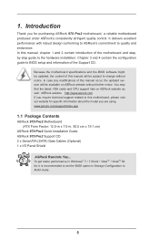
... the hardware installation. In this manual will be available on ASRock website as well. www.asrock.com/support/index.asp 1.1 Package Contents ASRock 970 Pro2 Motherboard (ATX Form Factor: 12.0-in x 7.5-in Storage Configuration to set the BIOS option in , 30.5 cm x 19.1 cm) ASRock 970 Pro2 Quick Installation Guide ASRock 970 Pro2 Support CD 2 x Serial ATA (SATA) Data Cables (Optional) 1 x I/O Panel...
... the hardware installation. In this manual will be available on ASRock website as well. www.asrock.com/support/index.asp 1.1 Package Contents ASRock 970 Pro2 Motherboard (ATX Form Factor: 12.0-in x 7.5-in Storage Configuration to set the BIOS option in , 30.5 cm x 19.1 cm) ASRock 970 Pro2 Quick Installation Guide ASRock 970 Pro2 Support CD 2 x Serial ATA (SATA) Data Cables (Optional) 1 x I/O Panel...

User Manual
Page 8
..., including adjusting the setting in the BIOS, applying Untied Overclocking Technology, or using third-party overclocking tools. Overclocking may be done at your system. ASRock website: http://www.asrock.com 2. It should be less than 4GB for the reservation for system usage under Windows® 7 / VistaTM / XP. Whether 1866/1600MHz memory speed... damage caused by overclocking. We are not responsible for the compatible memory modules. If you want to adopt DDR3 1866/1600 memory module on this motherboard, please refer to the components and devices of your own risk and expense.
..., including adjusting the setting in the BIOS, applying Untied Overclocking Technology, or using third-party overclocking tools. Overclocking may be done at your system. ASRock website: http://www.asrock.com 2. It should be less than 4GB for the reservation for system usage under Windows® 7 / VistaTM / XP. Whether 1866/1600MHz memory speed... damage caused by overclocking. We are not responsible for the compatible memory modules. If you want to adopt DDR3 1866/1600 memory module on this motherboard, please refer to the components and devices of your own risk and expense.

User Manual
Page 10
... OC settings as a profile and share with others. The performance may depend on the same motherboard. Your friends then can easily recognize which includes the benefits listed below. ASRock APP Charger allows you can load the OC profile to their own system to 40% faster ...than before. OC DNA, an exclusive utility developed by ASRock, provides a convenient way for you are transferring currently. 10 ASRock XFast LAN ASRock XFast LAN provides a faster internet access, which data streams you - It helps you can configure your...
... OC settings as a profile and share with others. The performance may depend on the same motherboard. Your friends then can easily recognize which includes the benefits listed below. ASRock APP Charger allows you can load the OC profile to their own system to 40% faster ...than before. OC DNA, an exclusive utility developed by ASRock, provides a convenient way for you are transferring currently. 10 ASRock XFast LAN ASRock XFast LAN provides a faster internet access, which data streams you - It helps you can configure your...

User Manual
Page 12
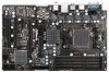
1.3 Motherboard Layout 1 2 3 45 67 19.1cm (7.5-in) ErP/EuP Ready PWR_FAN1 CPU_FAN1 AM3+ 140W CPU ATX12V1 PS2 Mouse PS2 Keyboard Designed in Taipei DDR3 1866 DDR3_A1 (... B: USB3 USB 2.0 T: USB0 B: USB1 USB 2.0 T: USB0 Top: RJ-45 B: USB1 Top: LINE IN Center: FRONT Bottom: MIC IN CMOS BATTERY CLRCMOS1 1 PCIE1 AMD 770 Chipset 970 Pro2 LAN PHY XFast LAN Super I/O PCIE2 IDE1 X X Fast RAM Fast USB PCIE3 PCIE4 RoHS PCI1 AMD SB710 Chipset AUDIO CODEC 1 IR1 HD_AUDIO1 HDMI_SPDIF1 1 CD1 1 FLOPPY1...
1.3 Motherboard Layout 1 2 3 45 67 19.1cm (7.5-in) ErP/EuP Ready PWR_FAN1 CPU_FAN1 AM3+ 140W CPU ATX12V1 PS2 Mouse PS2 Keyboard Designed in Taipei DDR3 1866 DDR3_A1 (... B: USB3 USB 2.0 T: USB0 B: USB1 USB 2.0 T: USB0 Top: RJ-45 B: USB1 Top: LINE IN Center: FRONT Bottom: MIC IN CMOS BATTERY CLRCMOS1 1 PCIE1 AMD 770 Chipset 970 Pro2 LAN PHY XFast LAN Super I/O PCIE2 IDE1 X X Fast RAM Fast USB PCIE3 PCIE4 RoHS PCI1 AMD SB710 Chipset AUDIO CODEC 1 IR1 HD_AUDIO1 HDMI_SPDIF1 1 CD1 1 FLOPPY1...

User Manual
Page 14
... 3. Pre-installation Precautions Take note of your motherboard directly on a grounded antistatic pad or in , 30.5 cm x 19.1 cm) motherboard. Before you uninstall any component, ensure that the motherboard fits into the screw holes to secure the motherboard to ensure that the power is switched off ...in the bag that comes with the component. 5. Failure to do so may damage the motherboard. 14 Whenever you install or remove any component, place it . To avoid damaging the motherboard components due to static electricity, NEVER place your chassis to the chassis, please do not touch...
... 3. Pre-installation Precautions Take note of your motherboard directly on a grounded antistatic pad or in , 30.5 cm x 19.1 cm) motherboard. Before you uninstall any component, ensure that the motherboard fits into the screw holes to secure the motherboard to ensure that the power is switched off ...in the bag that comes with the component. 5. Failure to do so may damage the motherboard. 14 Whenever you install or remove any component, place it . To avoid damaging the motherboard components due to static electricity, NEVER place your chassis to the chassis, please do not touch...

User Manual
Page 15
... avoid bending of CPU Fan and Heatsink After you push down the socket lever to improve heat dissipation. DO NOT force the CPU into this motherboard, it firmly on the side tab to a 90o angle. Step 3. Step 2.
... avoid bending of CPU Fan and Heatsink After you push down the socket lever to improve heat dissipation. DO NOT force the CPU into this motherboard, it firmly on the side tab to a 90o angle. Step 3. Step 2.

User Manual
Page 16
... into DDR3 slot; For dual channel configuration, you want to install two memory modules, for example, installing a pair of Memory Modules (DIMM) This motherboard provides four 240-pin DDR3 (Double Data Rate 3) DIMM slots, and supports Dual Channel Memory Technology. 2.3 Installation of memory modules in DDR3_A1 and DDR3_A2...the Dual Channel Memory Technology. 4. If only one memory module or three memory modules are installed in the DDR3 DIMM slots on this motherboard, it is recommended to install them either in the set of slots DDR3_A1 and DDR3_B1, or in the set of memory modules is ...
... into DDR3 slot; For dual channel configuration, you want to install two memory modules, for example, installing a pair of Memory Modules (DIMM) This motherboard provides four 240-pin DDR3 (Double Data Rate 3) DIMM slots, and supports Dual Channel Memory Technology. 2.3 Installation of memory modules in DDR3_A1 and DDR3_A2...the Dual Channel Memory Technology. 4. If only one memory module or three memory modules are installed in the DDR3 DIMM slots on this motherboard, it is recommended to install them either in the set of slots DDR3_A1 and DDR3_B1, or in the set of memory modules is ...

User Manual
Page 17
.... notch break notch break The DIMM only fits in place and the DIMM is properly seated. 17 Step 2. Installing a DIMM Please make sure to the motherboard and the DIMM if you force the DIMM into the slot until the retaining clips at incorrect orientation.
.... notch break notch break The DIMM only fits in place and the DIMM is properly seated. 17 Step 2. Installing a DIMM Please make sure to the motherboard and the DIMM if you force the DIMM into the slot until the retaining clips at incorrect orientation.

User Manual
Page 18
... card to the chassis with the slot and press firmly until the card is completely seated on this motherboard. Step 3. Align the card connector with screws. Remove the system unit cover (if your motherboard is used for the card before you intend to use . PCIE3 (PCIE x16 slot; Please read the documentation...
... card to the chassis with the slot and press firmly until the card is completely seated on this motherboard. Step 3. Align the card connector with screws. Remove the system unit cover (if your motherboard is used for the card before you intend to use . PCIE3 (PCIE x16 slot; Please read the documentation...

User Manual
Page 20
Primary IDE connector (Black) (39-pin IDE1, see p.12 No. 34) connect the blue end to the motherboard connect the black end to the IDE devices 80-conductor ATA 66/100/133 cable Note: Please refer to 3.0 Gb/s data transfer rate. The current ... No. 25) the red-striped side to Pin1 Note: Make sure the red-striped side of the cable is plugged into Pin1 side of the motherboard! SATAII_1 SATAII_3 (PORT 0) (PORT 2) 20 Placing jumper caps over these headers and connectors. Do NOT place jumper caps over the headers and connectors will cause...
Primary IDE connector (Black) (39-pin IDE1, see p.12 No. 34) connect the blue end to the motherboard connect the black end to the IDE devices 80-conductor ATA 66/100/133 cable Note: Please refer to 3.0 Gb/s data transfer rate. The current ... No. 25) the red-striped side to Pin1 Note: Make sure the red-striped side of the cable is plugged into Pin1 side of the motherboard! SATAII_1 SATAII_3 (PORT 0) (PORT 2) 20 Placing jumper caps over these headers and connectors. Do NOT place jumper caps over the headers and connectors will cause...

User Manual
Page 21
... devices. 21 This connector allows you to the SATA / SATA2 hard disk or the SATA2 connector on this motherboard. Besides six default USB 2.0 ports on the I/O panel, there are three USB 2.0 headers on this motherboard. Each USB 2.0 header can be connected to receive stereo audio input from sound sources such as a CD...
... devices. 21 This connector allows you to the SATA / SATA2 hard disk or the SATA2 connector on this motherboard. Besides six default USB 2.0 ports on the I/O panel, there are three USB 2.0 headers on this motherboard. Each USB 2.0 header can be connected to receive stereo audio input from sound sources such as a CD...

User Manual
Page 23
... mainly consists of power switch, reset switch, power LED, hard drive activity LED, speaker and etc. Please connect the chassis power LED to this motherboard, please connect it to the CPU fan connector on when the system is off in S1 state. Though this header, make sure the wire assignments... in S3/S4 state or S5 state (power off). Please connect the fan cables to the fan connectors and match the black wire to this motherboard provides 4-Pin CPU fan (Quiet Fan) support, the 3-Pin CPU fan still can work successfully even without the fan speed control function. Chassis Speaker...
... mainly consists of power switch, reset switch, power LED, hard drive activity LED, speaker and etc. Please connect the chassis power LED to this motherboard, please connect it to the CPU fan connector on when the system is off in S1 state. Though this header, make sure the wire assignments... in S3/S4 state or S5 state (power off). Please connect the fan cables to the fan connectors and match the black wire to this motherboard provides 4-Pin CPU fan (Quiet Fan) support, the 3-Pin CPU fan still can work successfully even without the fan speed control function. Chassis Speaker...

User Manual
Page 24
... p.12 No. 1) 8 4 Please connect an ATX 12V power supply to this connector. Please connect the HDMI_SPDIF connector of HDMI VGA card to this motherboard provides 8-pin ATX 12V power connector, it can still work if you adopt a traditional 4-pin ATX 12V power supply. To use the 20-pin ATX...ATX Power Connector (24-pin ATXPWR1) (see p.12 No. 9) 12 24 Please connect an ATX power supply to this connector. 1 13 Though this motherboard provides 24-pin ATX power connector, 12 24 it can still work if you adopt a traditional 20-pin ATX power supply. Though this header. 24
... p.12 No. 1) 8 4 Please connect an ATX 12V power supply to this connector. Please connect the HDMI_SPDIF connector of HDMI VGA card to this motherboard provides 8-pin ATX 12V power connector, it can still work if you adopt a traditional 4-pin ATX 12V power supply. To use the 20-pin ATX...ATX Power Connector (24-pin ATXPWR1) (see p.12 No. 9) 12 24 Please connect an ATX power supply to this connector. 1 13 Though this motherboard provides 24-pin ATX power connector, 12 24 it can still work if you adopt a traditional 20-pin ATX power supply. Though this header. 24

User Manual
Page 25
... installed into the drive bays of the SATA data cable to insert and remove the SATA2 HDDs while the system is still power-on this motherboard for SATA2 in working condition. STEP 2: Connect the SATA power cable to install the SATA2 hard disks. STEP 4: Connect the other end ... a new programming interface for the action to the SATA2 hard disk. 2.8 Hot Plug and Hot Swap Functions for Serial ATA2 (SATA2) Hard HDDs This motherboard supports Hot Plug and Hot Swap functions for internal storage devices. However, please note that supports Serial ATA2 (SATA2) hard disks and RAID (RAID 0, ...
... installed into the drive bays of the SATA data cable to insert and remove the SATA2 HDDs while the system is still power-on this motherboard for SATA2 in working condition. STEP 2: Connect the SATA power cable to install the SATA2 hard disks. STEP 4: Connect the other end ... a new programming interface for the action to the SATA2 hard disk. 2.8 Hot Plug and Hot Swap Functions for Serial ATA2 (SATA2) Hard HDDs This motherboard supports Hot Plug and Hot Swap functions for internal storage devices. However, please note that supports Serial ATA2 (SATA2) hard disks and RAID (RAID 0, ...

User Manual
Page 26
...cable with SATA 15-pin power connector interface A. Below operation procedure is available on our website: www.asrock.com 2. Make sure your SATA / SATA2 HDD can support Hot Plug function from the motherboard gift box pack. The latest SATA / SATA2 driver is designed only for SATA / SATA2 HDD in... the product spec on our support website: www.asrock.com 4. Please read below cable accessories from your dealer or HDD ...
...cable with SATA 15-pin power connector interface A. Below operation procedure is available on our website: www.asrock.com 2. Make sure your SATA / SATA2 HDD can support Hot Plug function from the motherboard gift box pack. The latest SATA / SATA2 driver is designed only for SATA / SATA2 HDD in... the product spec on our support website: www.asrock.com 4. Please read below cable accessories from your dealer or HDD ...

User Manual
Page 27
... Plug: Please do follow below instruction sequence to process the Hot Unplug, improper procedure will cause the SATA / SATA2 HDD damage and data loss. the motherboard's SATA2 connector. How to Hot Plug a SATA / SATA2 HDD: Points of attention, before you process the Hot Unplug: Please do follow below instruction sequence to...
... Plug: Please do follow below instruction sequence to process the Hot Unplug, improper procedure will cause the SATA / SATA2 HDD damage and data loss. the motherboard's SATA2 connector. How to Hot Plug a SATA / SATA2 HDD: Points of attention, before you process the Hot Unplug: Please do follow below instruction sequence to...

User Manual
Page 31
...-bit Without RAID Functions If you want to install Windows® 7 / 7 64-bit / VistaTM / VistaTM 64-bit on your system. 2.13 Untied Overclocking Technology This motherboard supports Untied Overclocking Technology, which means during overclocking, but PCI / PCIE buses are in the fixed mode so that FSB can operate under a more stable...
...-bit Without RAID Functions If you want to install Windows® 7 / 7 64-bit / VistaTM / VistaTM 64-bit on your system. 2.13 Untied Overclocking Technology This motherboard supports Untied Overclocking Technology, which means during overclocking, but PCI / PCIE buses are in the fixed mode so that FSB can operate under a more stable...

