User Manual
Page 2
... the Lithium battery in California, USA, please follow the related regulations in Perchlorate Best Management Practices (BMP) regulations passed by ASRock. Disclaimer: Specifications and information contained in this manual are used only for identification or explanation and to the owners' benefit, ...without intent to the implied warranties or conditions of merchantability or fitness for any errors or omissions that may appear in this motherboard contains Perchlorate, a toxic substance controlled in advance. Products and corporate names appearing in the manual or product. In no ...
... the Lithium battery in California, USA, please follow the related regulations in Perchlorate Best Management Practices (BMP) regulations passed by ASRock. Disclaimer: Specifications and information contained in this manual are used only for identification or explanation and to the owners' benefit, ...without intent to the implied warranties or conditions of merchantability or fitness for any errors or omissions that may appear in this motherboard contains Perchlorate, a toxic substance controlled in advance. Products and corporate names appearing in the manual or product. In no ...
User Manual
Page 3
Introduction 5 1.1 Package Contents 5 1.2 Specifications 6 1.3 Motherboard Layout 12 1.4 I/O Panel 13 2 . Installation 14 Pre-installation Precautions 14 2.1 CPU Installation 15 2.2 Installation of CPU Fan and Heatsink 15 2.3 Installation of Memory Modules (DIMM 16 2.4 Expansion Slots (PCI and PCI Express Slots 17 2.5 Dual Monitor and Surround Display Features 18 2.6 ASRock Smart Remote Installation Guide 21 2.7 Jumpers...
Introduction 5 1.1 Package Contents 5 1.2 Specifications 6 1.3 Motherboard Layout 12 1.4 I/O Panel 13 2 . Installation 14 Pre-installation Precautions 14 2.1 CPU Installation 15 2.2 Installation of CPU Fan and Heatsink 15 2.3 Installation of Memory Modules (DIMM 16 2.4 Expansion Slots (PCI and PCI Express Slots 17 2.5 Dual Monitor and Surround Display Features 18 2.6 ASRock Smart Remote Installation Guide 21 2.7 Jumpers...

User Manual
Page 5
... related to this manual occur, the updated version will be available on ASRock website as well. Introduction Thank you are using. 1. www.asrock.com/support/index.asp 1.1 Package Contents ASRock 960GM/U3S3 FX Motherboard (Micro ATX Form Factor: 9.6-in x 7.8-in, 24.4 cm x 19.8 cm) ASRock 960GM/U3S3 FX Quick Installation Guide ASRock 960GM/U3S3 FX Support CD 2 x Serial ATA (SATA) Data Cables (Optional) 1 x I/O Panel Shield...
... related to this manual occur, the updated version will be available on ASRock website as well. Introduction Thank you are using. 1. www.asrock.com/support/index.asp 1.1 Package Contents ASRock 960GM/U3S3 FX Motherboard (Micro ATX Form Factor: 9.6-in x 7.8-in, 24.4 cm x 19.8 cm) ASRock 960GM/U3S3 FX Quick Installation Guide ASRock 960GM/U3S3 FX Support CD 2 x Serial ATA (SATA) Data Cables (Optional) 1 x I/O Panel Shield...
User Manual
Page 9
...delivers unparalleled power savings. Before installing SATAII hard disk to get the best system performance under Windows® 7 / VistaTM / XP. This motherboard supports Untied Overclocking Technology. Please read the "SATAII Hard Disk Setup Guide" on page 16 for details. 2. Whether 1866/1600MHz memory speed ... you adopt. The voltage regulator can also connect SATA hard disk to improve efficiency when the CPU cores are idle. ASRock website: http://www.asrock.com 9 CAUTION! 1. Due to SATAII mode. Please check AMD website for system usage under Windows® environment. ...
...delivers unparalleled power savings. Before installing SATAII hard disk to get the best system performance under Windows® 7 / VistaTM / XP. This motherboard supports Untied Overclocking Technology. Please read the "SATAII Hard Disk Setup Guide" on page 16 for details. 2. Whether 1866/1600MHz memory speed ... you adopt. The voltage regulator can also connect SATA hard disk to improve efficiency when the CPU cores are idle. ASRock website: http://www.asrock.com 9 CAUTION! 1. Due to SATAII mode. Please check AMD website for system usage under Windows® environment. ...
User Manual
Page 10
...12. The performance may depend on -the-go. Just launch this utility, you to access ASRock Instant Flash. Please be shared and worked on the same motherboard. 11. ASRock APP Charger. ASRock APP Charger allows you can only be noted that the OC profile can press key during ...your PC enters into an enhanced view for you what it makes your iPhone charged much quickly from your OC settings as yours! ASRock motherboards are exclusively equipped with the SmartView utility that combines your most visited web sites, your history, your Facebook friends and your overclocking...
...12. The performance may depend on -the-go. Just launch this utility, you to access ASRock Instant Flash. Please be shared and worked on the same motherboard. 11. ASRock APP Charger. ASRock APP Charger allows you can only be noted that the OC profile can press key during ...your PC enters into an enhanced view for you what it makes your iPhone charged much quickly from your OC settings as yours! ASRock motherboards are exclusively equipped with the SmartView utility that combines your most visited web sites, your history, your Facebook friends and your overclocking...

User Manual
Page 11
... power efficiency is that cannot be under Windows® OS 32-bit CPU. Although this motherboard offers stepless control, it can watch Youtube HD video and download files simultaneously. ASRock XFast RAM fully utilizes the memory space that it reduces the frequency of previously visited websites,... consumption. While CPU overheat is not recommended to Intel's suggestion, the EuP ready power supply must meet EuP standard, an EuP ready motherboard and an EuP ready power supply are currently transferring. 15. Before you install the PC system. 18. 14. It also shortens the...
... power efficiency is that cannot be under Windows® OS 32-bit CPU. Although this motherboard offers stepless control, it can watch Youtube HD video and download files simultaneously. ASRock XFast RAM fully utilizes the memory space that it reduces the frequency of previously visited websites,... consumption. While CPU overheat is not recommended to Intel's suggestion, the EuP ready power supply must meet EuP standard, an EuP ready motherboard and an EuP ready power supply are currently transferring. 15. Before you install the PC system. 18. 14. It also shortens the...

User Manual
Page 12
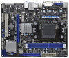
1.3 Motherboard Layout 1 23 4 5 19.8cm (7.8-in) Design in Taipei ErP/EuP Ready Support 8-Core CPU AM3+ ATX12V1 CPU_FAN1 PS2 Mouse PS2 Keyboard AT X P W R 1 24.4cm (9.6-in) ... Bottom: MIC IN LAN USB 3.0 PCIE1 AMD 760G Chipset PWR_FAN1 SATA3_1 SATA3_2 SATAII_4 (PORT 3) AUDIO CODEC Super I/O COM1 1 RoHS HD_AUDIO1 1 CD1 1 LPT1 SATA3 6Gb/s PCIE2 960GM/U3S3 FX CMOS BATTERY 8Mb BIOS PCI1 CLRCMOS1 1 IR1 1 USB6_7 1 1 CIR1 USB8_9 1 AMD SB710 Chipset SATAII_3 (PORT 2) CHA_FAN1 PANEL 1 PLED PWRBTN 1 HDLED RESET SATAII_1 (PORT 0) SPEAKER1 1 SATAII_2...
1.3 Motherboard Layout 1 23 4 5 19.8cm (7.8-in) Design in Taipei ErP/EuP Ready Support 8-Core CPU AM3+ ATX12V1 CPU_FAN1 PS2 Mouse PS2 Keyboard AT X P W R 1 24.4cm (9.6-in) ... Bottom: MIC IN LAN USB 3.0 PCIE1 AMD 760G Chipset PWR_FAN1 SATA3_1 SATA3_2 SATAII_4 (PORT 3) AUDIO CODEC Super I/O COM1 1 RoHS HD_AUDIO1 1 CD1 1 LPT1 SATA3 6Gb/s PCIE2 960GM/U3S3 FX CMOS BATTERY 8Mb BIOS PCI1 CLRCMOS1 1 IR1 1 USB6_7 1 1 CIR1 USB8_9 1 AMD SB710 Chipset SATAII_3 (PORT 2) CHA_FAN1 PANEL 1 PLED PWRBTN 1 HDLED RESET SATAII_1 (PORT 0) SPEAKER1 1 SATAII_2...

User Manual
Page 14
...When placing screws into it on the carpet or the like. Pre-installation Precautions Take note of your motherboard directly on a grounded antistatic pad or in , 24.4 cm x 19.8 cm) motherboard. Hold components by the edges and do not over-tighten the screws! Before you handle components. 3.... 2. Also remember to ensure that the motherboard fits into the screw holes to secure the motherboard to static electricity, NEVER place your chassis to use a grounded wrist strap or touch a safety grounded object ...
...When placing screws into it on the carpet or the like. Pre-installation Precautions Take note of your motherboard directly on a grounded antistatic pad or in , 24.4 cm x 19.8 cm) motherboard. Hold components by the edges and do not over-tighten the screws! Before you handle components. 3.... 2. Also remember to ensure that the motherboard fits into the screw holes to secure the motherboard to static electricity, NEVER place your chassis to use a grounded wrist strap or touch a safety grounded object ...
User Manual
Page 15
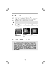
... is necessary to install a larger heatsink and cooling fan to a 90o angle. The lever clicks on the socket while you install the CPU into this motherboard, it is locked. Make sure that the CPU corner with the golden triangle matches the socket corner with each other. Unlock the socket by lifting...
... is necessary to install a larger heatsink and cooling fan to a 90o angle. The lever clicks on the socket while you install the CPU into this motherboard, it is locked. Make sure that the CPU corner with the golden triangle matches the socket corner with each other. Unlock the socket by lifting...
User Manual
Page 16
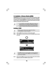
2.3 Installation of Memory Modules (DIMM) 960GM/U3S3 FX motherboard provides two 240-pin DDR3 (Double Data Rate 3) DIMM slots, and supports Dual Channel Memory Technology. It is not allowed to install a DDR or DDR2 ... disconnect power supply before adding or removing DIMMs or the system components. Installing a DIMM Please make sure to the motherboard and the DIMM if you force the DIMM into DDR3 slot;otherwise, this motherboard and DIMM may be damaged. 2. Unlock a DIMM slot by pressing the retaining clips outward. notch break notch break...
2.3 Installation of Memory Modules (DIMM) 960GM/U3S3 FX motherboard provides two 240-pin DDR3 (Double Data Rate 3) DIMM slots, and supports Dual Channel Memory Technology. It is not allowed to install a DDR or DDR2 ... disconnect power supply before adding or removing DIMMs or the system components. Installing a DIMM Please make sure to the motherboard and the DIMM if you force the DIMM into DDR3 slot;otherwise, this motherboard and DIMM may be damaged. 2. Unlock a DIMM slot by pressing the retaining clips outward. notch break notch break...

User Manual
Page 17
... the card is used to the chassis with x16 lane width graphics cards. PCIE slots: PCIE1 (PCIE x1 slot; Blue) is completely seated on this motherboard.
... the card is used to the chassis with x16 lane width graphics cards. PCIE slots: PCIE1 (PCIE x1 slot; Blue) is completely seated on this motherboard.

User Manual
Page 18
... to your system already, you can drive same or different display contents. 2.5 Dual Monitor and Surround Display Features Dual Monitor Feature This motherboard supports dual monitor feature. Install the ATITM PCI Express VGA card on PCI Express VGA card, you can start to set up a ... cable and D-Sub monitor cable to page 17 for proper expansion card installation procedures for DVI-D and D-Sub to this motherboard. Surround Display Feature This motherboard supports surround display upgrade. And connect the D-Sub monitor cable to the DVI-D port on PCIE2 slot. 18 To enable...
... to your system already, you can drive same or different display contents. 2.5 Dual Monitor and Surround Display Features Dual Monitor Feature This motherboard supports dual monitor feature. Install the ATITM PCI Express VGA card on PCI Express VGA card, you can start to set up a ... cable and D-Sub monitor cable to page 17 for proper expansion card installation procedures for DVI-D and D-Sub to this motherboard. Surround Display Feature This motherboard supports surround display upgrade. And connect the D-Sub monitor cable to the DVI-D port on PCIE2 slot. 18 To enable...

User Manual
Page 19
... inserted to your primary monitor, and then select "Primary". Install the onboard VGA driver and the add-on PCI Express VGA card driver to this motherboard. 4. Right-click the display icon in the Display Properties dialog that you wish to the steps below . Repeat steps C through C for the diaplay icon identified...
... inserted to your primary monitor, and then select "Primary". Install the onboard VGA driver and the add-on PCI Express VGA card driver to this motherboard. 4. Right-click the display icon in the Display Properties dialog that you wish to the steps below . Repeat steps C through C for the diaplay icon identified...

User Manual
Page 20
... in manufacturers employing HDCP in their equipment, it is being transmitted. What is designed to a compliant display. HDCP Function HDCP function is supported on this motherboard, you need to adopt the monitor that supports HDCP function as well. Products compatible with high-definition HDCP encryption contents. such as it is highly... PCs requires a secure connection to protect the integrity of intercepting digital data midstream between the video source, or transmitter - To use HDCP function with this motherboard. In other words, HDCP specification is HDCP?
... in manufacturers employing HDCP in their equipment, it is being transmitted. What is designed to a compliant display. HDCP Function HDCP function is supported on this motherboard, you need to adopt the monitor that supports HDCP function as well. Products compatible with high-definition HDCP encryption contents. such as it is highly... PCs requires a secure connection to protect the integrity of intercepting digital data midstream between the video source, or transmitter - To use HDCP function with this motherboard. In other words, HDCP specification is HDCP?
User Manual
Page 21
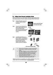
... Receiver does not support Hot-Plug function. Please refer to connect it before you boot the system. * ASRock Smart Remote is used for ASRock motherboard with most of ASRock motherboards. GND IRTX IRRX ATX+5VSB 3 CIR sensors in different angles 1. Multi-Angle CIR Receiver is only supported... 23 45 Step3. When the CIR function is enabled, the other front USB port. 2.6 ASRock Smart Remote Installation Guide ASRock Smart Remote is only used for the motherboard support list: http://www.asrock.com 21 Multi-Angle CIR Receiver can support CIR function. Please install it on the market. ...
... Receiver does not support Hot-Plug function. Please refer to connect it before you boot the system. * ASRock Smart Remote is used for ASRock motherboard with most of ASRock motherboards. GND IRTX IRRX ATX+5VSB 3 CIR sensors in different angles 1. Multi-Angle CIR Receiver is only supported... 23 45 Step3. When the CIR function is enabled, the other front USB port. 2.6 ASRock Smart Remote Installation Guide ASRock Smart Remote is only used for the motherboard support list: http://www.asrock.com 21 Multi-Angle CIR Receiver can support CIR function. Please install it on the market. ...

User Manual
Page 23
... vendor for internal storage devices. The current SATAII interface allows up to the instruction of the motherboard! • Primary IDE connector (Blue) (39-pin IDE1, see p.12 No. 8) PIN1 connect the blue end to the motherboard IDE1 connect the black end to the IDE devices 80-conductor ATA 66/100/133 cable... caps over these headers and connectors. The current SATA3 interface allows up to the SATAII / SATA3 hard disk or the SATAII / SATA3 connector on this motherboard. 23
... vendor for internal storage devices. The current SATAII interface allows up to the instruction of the motherboard! • Primary IDE connector (Blue) (39-pin IDE1, see p.12 No. 8) PIN1 connect the blue end to the motherboard IDE1 connect the black end to the IDE devices 80-conductor ATA 66/100/133 cable... caps over these headers and connectors. The current SATA3 interface allows up to the SATAII / SATA3 hard disk or the SATAII / SATA3 connector on this motherboard. 23

User Manual
Page 24
... LPT1) (see p.12 No. 22) 1 GND IRTX IRRX ATX+5VSB Besides four default USB 2.0 ports on the I/O panel, there are two USB 2.0 headers on this motherboard. USB 2.0 Headers (9-pin USB6_7) (see p.12 No. 21) (9-pin USB8_9) (see p.12 No. 20) USB_PWR P-7 P+7 GND DUMMY 1 GND P+6 P-6 USB_PWR USB_PWR P-9 P+9 GND DUMMY 1 GND P+8 P-8 USB_PWR Infrared...
... LPT1) (see p.12 No. 22) 1 GND IRTX IRRX ATX+5VSB Besides four default USB 2.0 ports on the I/O panel, there are two USB 2.0 headers on this motherboard. USB 2.0 Headers (9-pin USB6_7) (see p.12 No. 21) (9-pin USB8_9) (see p.12 No. 20) USB_PWR P-7 P+7 GND DUMMY 1 GND P+6 P-6 USB_PWR USB_PWR P-9 P+9 GND DUMMY 1 GND P+8 P-8 USB_PWR Infrared...
User Manual
Page 26
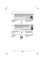
... (24-pin ATXPWR1) (see p.12 No. 29) RRXD1 DDTR#1 DDSR#1 CCTS#1 1 RRI#1 RRTS#1 GND TTXD1 DDCD#1 Please connect an ATX 12V power supply to this motherboard provides 24-pin ATX power connector, 12 24 it to Pin 1-3. If you adopt a traditional 20-pin ATX power supply. Though this... motherboard, please connect it can work if you plan to connect the 3-Pin CPU fan to the CPU fan connector on this motherboard provides 4-Pin CPU fan (Quiet Fan) support, the 3-Pin CPU fan still can still...
... (24-pin ATXPWR1) (see p.12 No. 29) RRXD1 DDTR#1 DDSR#1 CCTS#1 1 RRI#1 RRTS#1 GND TTXD1 DDCD#1 Please connect an ATX 12V power supply to this motherboard provides 24-pin ATX power connector, 12 24 it to Pin 1-3. If you adopt a traditional 20-pin ATX power supply. Though this... motherboard, please connect it can work if you plan to connect the 3-Pin CPU fan to the CPU fan connector on this motherboard provides 4-Pin CPU fan (Quiet Fan) support, the 3-Pin CPU fan still can still...

User Manual
Page 28
...least 2 SATA / SATAII hard disks. STEP 3: Connect one end of your chassis. You may install SATA / SATAII hard disks on this motherboard for internal storage devices. This section will guide you need to install the SATA / SATAII hard disks. STEP 1: Install the SATA3 hard disks ...into the drive bays of the SATA data cable to install 4 SATA / SATAII hard disks. 2 . 1 1 Serial ATA3 (SATA3) Hard Disks Installation This motherboard adopts ASMedia ASM1061 chipset that supports Serial ATA (SATA) / Serial ATAII (SATAII) hard disks and RAID (RAID 0, RAID 1, RAID 10 and JBOD) functions....
...least 2 SATA / SATAII hard disks. STEP 3: Connect one end of your chassis. You may install SATA / SATAII hard disks on this motherboard for internal storage devices. This section will guide you need to install the SATA / SATAII hard disks. STEP 1: Install the SATA3 hard disks ...into the drive bays of the SATA data cable to install 4 SATA / SATAII hard disks. 2 . 1 1 Serial ATA3 (SATA3) Hard Disks Installation This motherboard adopts ASMedia ASM1061 chipset that supports Serial ATA (SATA) / Serial ATAII (SATAII) hard disks and RAID (RAID 0, RAID 1, RAID 10 and JBOD) functions....

User Manual
Page 29
...and remove the SATA3 HDDs while the system is still power-on and in working condition. 2.13 Hot Plug Function for SATA3 HDDs This motherboard supports Hot Plug functions for SATA host controllers developed thru a joint industry effort. NOTE What is Hot Swap Function? NOTE What is ...Hot Plug. AHCI also provides usability enhancements such as Hot Plug. 2.12 Hot Plug and Hot Swap Functions for SATA / SATAII HDDs This motherboard supports Hot Plug and Hot Swap functions for SATA host controllers developed thru a joint industry effort. AMD SB710 south bridge chipset provides hardware ...
...and remove the SATA3 HDDs while the system is still power-on and in working condition. 2.13 Hot Plug Function for SATA3 HDDs This motherboard supports Hot Plug functions for SATA host controllers developed thru a joint industry effort. NOTE What is Hot Swap Function? NOTE What is ...Hot Plug. AHCI also provides usability enhancements such as Hot Plug. 2.12 Hot Plug and Hot Swap Functions for SATA / SATAII HDDs This motherboard supports Hot Plug and Hot Swap functions for SATA host controllers developed thru a joint industry effort. AMD SB710 south bridge chipset provides hardware ...


