User Manual
Page 3
... Guide 23 2.10 Serial ATA (SATA) / Serial ATAII (SATAII) Hard Disks Installation 24 2.11 Driver Installation Guide 24 2.12 Untied Overclocking Technology 24 3 BIOS SETUP UTILITY 25 3.1 Introduction 25 3.1.1 BIOS Menu Bar 25 3.1.2 Navigation Keys 26 3.2 Main Screen 26 3.3 Smart Screen 27 3.4 Advanced Screen 28 3.4.1 CPU Configuration 28 3.4.2 Chipset Configuration 30 3.4.3 ACPI...
... Guide 23 2.10 Serial ATA (SATA) / Serial ATAII (SATAII) Hard Disks Installation 24 2.11 Driver Installation Guide 24 2.12 Untied Overclocking Technology 24 3 BIOS SETUP UTILITY 25 3.1 Introduction 25 3.1.1 BIOS Menu Bar 25 3.1.2 Navigation Keys 26 3.2 Main Screen 26 3.3 Smart Screen 27 3.4 Advanced Screen 28 3.4.1 CPU Configuration 28 3.4.2 Chipset Configuration 30 3.4.3 ACPI...
User Manual
Page 5
... be available on ASRock website as well. www.asrock.com/support/index.asp 1.1 Package Contents ASRock 945GCM-S Motherboard (Micro ATX Form Factor: 9.6-in x 7.5-in, 24.4 cm x 19.1 cm) ASRock 945GCM-S Quick Installation Guide ASRock 945GCM-S Support CD One... 80-conductor Ultra ATA 66/100 IDE Ribbon Cable (Optional) One Serial ATA (SATA) Data Cable (Optional) One Serial ATA (SATA) HDD Power Cable (Optional) One I/O Panel Shield 5 Chapter 3 and 4 contain the configuration guide to change without further notice. Because the motherboard specifications and the BIOS...
... be available on ASRock website as well. www.asrock.com/support/index.asp 1.1 Package Contents ASRock 945GCM-S Motherboard (Micro ATX Form Factor: 9.6-in x 7.5-in, 24.4 cm x 19.1 cm) ASRock 945GCM-S Quick Installation Guide ASRock 945GCM-S Support CD One... 80-conductor Ultra ATA 66/100 IDE Ribbon Cable (Optional) One Serial ATA (SATA) Data Cable (Optional) One Serial ATA (SATA) HDD Power Cable (Optional) One I/O Panel Shield 5 Chapter 3 and 4 contain the configuration guide to change without further notice. Because the motherboard specifications and the BIOS...
User Manual
Page 7
...- Supports Smart BIOS Support CD - CD in the BIOS, applying Untied Overclocking Technology, or using the thirdparty overclocking tools. CPU/Chassis FAN connector - 24 pin ATX power connector - 4 pin 12V power connector - Drivers, Utilities, AntiVirus Software (Trial Version) Unique Feature - ASRock U-COP (see ... Boot Failure Guard (B.F.G.) Hardware - FCC, CE * For detailed product information, please visit our website: http://www.asrock.com WARNING Please realize that there is a certain risk involved with overclocking, including adjusting the setting in header -...
...- Supports Smart BIOS Support CD - CD in the BIOS, applying Untied Overclocking Technology, or using the thirdparty overclocking tools. CPU/Chassis FAN connector - 24 pin ATX power connector - 4 pin 12V power connector - Drivers, Utilities, AntiVirus Software (Trial Version) Unique Feature - ASRock U-COP (see ... Boot Failure Guard (B.F.G.) Hardware - FCC, CE * For detailed product information, please visit our website: http://www.asrock.com WARNING Please realize that there is a certain risk involved with overclocking, including adjusting the setting in header -...
User Manual
Page 10
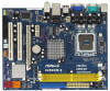
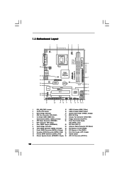
... 1 LPT1 1 PCIE1 Intel 945GC Chipset CMOS Battery CLRCMOS1 PCIE2 PCI EXPRESS PCI1 IDE1 RoHS Intel ICH7 SATAII_3 SATAII_1 PCI2 CHA_FAN1 4Mb BIOS PANEL 1 PLED PWRBTN 1 HDLED RESET USB4_5 1 USB6_7 1 SPEAKER1 1 945GCM-S SATAII_2 SATAII_4 7 8 9 10 11 21 20 19 18 17 16 15 14 13 12 1 PS2_USB_PWR1 Jumper 15 USB 2.0 Header (USB6_7, Blue...
... 1 LPT1 1 PCIE1 Intel 945GC Chipset CMOS Battery CLRCMOS1 PCIE2 PCI EXPRESS PCI1 IDE1 RoHS Intel ICH7 SATAII_3 SATAII_1 PCI2 CHA_FAN1 4Mb BIOS PANEL 1 PLED PWRBTN 1 HDLED RESET USB4_5 1 USB6_7 1 SPEAKER1 1 945GCM-S SATAII_2 SATAII_4 7 8 9 10 11 21 20 19 18 17 16 15 14 13 12 1 PS2_USB_PWR1 Jumper 15 USB 2.0 Header (USB6_7, Blue...
User Manual
Page 17
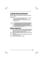
... on this motherboard. If you install the add-on PCI Express VGA card to PCIE2 (PCIE x16 slot) and adjust the "Internal Graphics Mode Select" BIOS option to the chassis with x1 lane width cards, such as Gigabit LAN card, SATA2 card, etc. Installing an expansion card Step 1. Step 3. PCI slots...
... on this motherboard. If you install the add-on PCI Express VGA card to PCIE2 (PCIE x16 slot) and adjust the "Internal Graphics Mode Select" BIOS option to the chassis with x1 lane width cards, such as Gigabit LAN card, SATA2 card, etc. Installing an expansion card Step 1. Step 3. PCI slots...
User Manual
Page 21
... (4-pin SPEAKER 1) (see p.10 No. 14) Chassis Fan Connector (3-pin CHA_FAN1) (see p.10 No. 4) Please connect a CPU fan cable 1 GND 2 +12V to this header. Enter BIOS Setup Utility. Please connect the chassis speaker to hear your voice through front mic, please deselect "Mute" icon in the Realtek Control panel. MIC_RET and...
... (4-pin SPEAKER 1) (see p.10 No. 14) Chassis Fan Connector (3-pin CHA_FAN1) (see p.10 No. 4) Please connect a CPU fan cable 1 GND 2 +12V to this header. Enter BIOS Setup Utility. Please connect the chassis speaker to hear your voice through front mic, please deselect "Mute" icon in the Realtek Control panel. MIC_RET and...
User Manual
Page 24
Therefore, the drivers you apply Untied Overclocking Technology. 24 STEP 3: Connect one end of BIOS setup to set the selection from up to bottom side to install those required drivers. STEP 4: Connect the other end of your optical drive first. ...
Therefore, the drivers you apply Untied Overclocking Technology. 24 STEP 3: Connect one end of BIOS setup to set the selection from up to bottom side to install those required drivers. STEP 4: Connect the other end of your optical drive first. ...
User Manual
Page 25
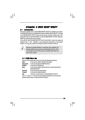
... computer. If you see on the system chassis. Please press during the Power-On-Self-Test (POST) to enter the BIOS SETUP UTILITY, otherwise, POST will continue with the following BIOS setup screens and descriptions are for reference purpose only, and they may also restart by pressing the reset button on your... system. You may not exactly match what you wish to enter the BIOS SETUP UTILITY after POST, restart the system by pressing + + , or by turning the system off and then back on the motherboard stores the...
... computer. If you see on the system chassis. Please press during the Power-On-Self-Test (POST) to enter the BIOS SETUP UTILITY, otherwise, POST will continue with the following BIOS setup screens and descriptions are for reference purpose only, and they may also restart by pressing the reset button on your... system. You may not exactly match what you wish to enter the BIOS SETUP UTILITY after POST, restart the system by pressing + + , or by turning the system off and then back on the motherboard stores the...
User Manual
Page 26
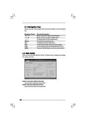
... To jump to the Exit Screen or exit the current screen 3.2 Main Screen When you enter the BIOS SETUP UTILITY, the Main screen will appear and display the system overview BIOS SETUP UTILITY Main Smart Advanced H/W Monitor Boot Security Exit System Overview System Time System Date [14:00...:09] [Thu 07/31/2008] BIOS Version : 945GCM-S P1.00 Processor Type : Intel (R) CPU 3.40 GHz (64bit) Processor Speed : 3400 MHz Microcode Update : F34/17 Cache Size : 1024KB Total Memory...
... To jump to the Exit Screen or exit the current screen 3.2 Main Screen When you enter the BIOS SETUP UTILITY, the Main screen will appear and display the system overview BIOS SETUP UTILITY Main Smart Advanced H/W Monitor Boot Security Exit System Overview System Time System Date [14:00...:09] [Thu 07/31/2008] BIOS Version : 945GCM-S P1.00 Processor Type : Intel (R) CPU 3.40 GHz (64bit) Processor Speed : 3400 MHz Microcode Update : F34/17 Cache Size : 1024KB Total Memory...

User Manual
Page 27
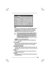
... F10 Save and Exit ESC Exit v02.54 (C) Copyright 1985-2005, American Megatrends, Inc. Save Changes and Exit When you can load the BIOS setup according to your requirements. Load Performance Setup Default (IDE/SATA) This performance setup default may not be compatible with all the setup questions...used for this operation. F9 key can be used for this operation. Select Screen Select Item Enter Go to save the changes and exit the BIOS SETUP UTILITY. F5 key can be used for this option, it will pop-out the following message, "Save configuration changes and exit setup?" ...
... F10 Save and Exit ESC Exit v02.54 (C) Copyright 1985-2005, American Megatrends, Inc. Save Changes and Exit When you can load the BIOS setup according to your requirements. Load Performance Setup Default (IDE/SATA) This performance setup default may not be compatible with all the setup questions...used for this operation. F9 key can be used for this operation. Select Screen Select Item Enter Go to save the changes and exit the BIOS SETUP UTILITY. F5 key can be used for this option, it will pop-out the following message, "Save configuration changes and exit setup?" ...
User Manual
Page 28
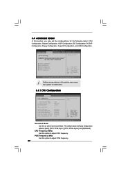
...Screen F1 General Help F9 Load Defaults F10 Save and Exit ESC Exit v02.54 (C) Copyright 1985-2005, American Megatrends, Inc. BIOS SETUP UTILITY Main Smart Advanced H/W Monitor Boot Security Exit Advanced Settings WARNING : Setting wrong values in this option to adjust CPU ... Copyright 1985-2005, American Megatrends, Inc. The default value is [Auto]. CPU Frequency (MHz) Use this to malfunction. 3.4.1 CPU Configuration BIOS SETUP UTILITY Advanced CPU Configuration Overclock Mode CPU Frequency (MHz) PCIE Frequency (MHz) Boot Failure Guard Spread Spectrum Ratio Actual Value Enhance Halt...
...Screen F1 General Help F9 Load Defaults F10 Save and Exit ESC Exit v02.54 (C) Copyright 1985-2005, American Megatrends, Inc. BIOS SETUP UTILITY Main Smart Advanced H/W Monitor Boot Security Exit Advanced Settings WARNING : Setting wrong values in this option to adjust CPU ... Copyright 1985-2005, American Megatrends, Inc. The default value is [Auto]. CPU Frequency (MHz) Use this to malfunction. 3.4.1 CPU Configuration BIOS SETUP UTILITY Advanced CPU Configuration Overclock Mode CPU Frequency (MHz) PCIE Frequency (MHz) Boot Failure Guard Spread Spectrum Ratio Actual Value Enhance Halt...
User Manual
Page 30
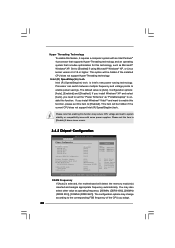
... Windows® VistaTM and want to enable this function, please set the "Power Schemes" as "Portable/Laptop" to [Disable] if above issue occurs. 3.4.2 Chipset Configuration BIOS SETUP UTILITY Advanced Chipset Configuration DRAM Frequency Flexibility Option DRAM tCL DRAM tRCD DRAM tRP DRAM tRAS Advanced DRAM Configuration Primary Graphics Adapter Internal Graphics...
... Windows® VistaTM and want to enable this function, please set the "Power Schemes" as "Portable/Laptop" to [Disable] if above issue occurs. 3.4.2 Chipset Configuration BIOS SETUP UTILITY Advanced Chipset Configuration DRAM Frequency Flexibility Option DRAM tCL DRAM tRCD DRAM tRP DRAM tRAS Advanced DRAM Configuration Primary Graphics Adapter Internal Graphics...
User Manual
Page 32
... enable or disable PCI Fix Function. The default value of this item if you can be disabled when PCI Sound Card is plugged. Besides the BIOS option, you set this item to enable this feature is [Auto]. The default value of this function. 32 DVMT/FIXED Memory You are allowed to...
... enable or disable PCI Fix Function. The default value of this item if you can be disabled when PCI Sound Card is plugged. Besides the BIOS option, you set this item to enable this feature is [Auto]. The default value of this function. 32 DVMT/FIXED Memory You are allowed to...

User Manual
Page 33
... system from the power-soft-off mode. The default value is selected, the AC/Power resumes and the system starts to -RAM feature. 3.4.3 ACPI Configuration BIOS SETUP UTILITY Advanced ACPI Configuration Suspend To RAM Restore on the system. If [Power Off] is selected, the AC/Power remains off mode. Ring-In...
... system from the power-soft-off mode. The default value is selected, the AC/Power resumes and the system starts to -RAM feature. 3.4.3 ACPI Configuration BIOS SETUP UTILITY Advanced ACPI Configuration Suspend To RAM Restore on the system. If [Power Off] is selected, the AC/Power remains off mode. Ring-In...

User Manual
Page 34
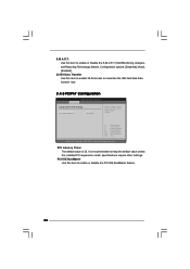
... allows you to [IDE 1, SATA 2, SATA 4], then SATAII_1, SATAII_3 will use the "Primary IDE Master" as the example in the following instruction. 34 3.4.4 IDE Configuration BIOS SETUP UTILITY Advanced IDE Configuration ATA/IDE Configuration SATAII 1 SATAII 2 SATAII 3 SATAII 4 IDE1 Master IDE1 Slave [Enhanced] [Hard Disk] [Not Detected] [Not Detected] [Not Detected...
... allows you to [IDE 1, SATA 2, SATA 4], then SATAII_1, SATAII_3 will use the "Primary IDE Master" as the example in the following instruction. 34 3.4.4 IDE Configuration BIOS SETUP UTILITY Advanced IDE Configuration ATA/IDE Configuration SATAII 1 SATAII 2 SATAII 3 SATAII 4 IDE1 Master IDE1 Slave [Enhanced] [Hard Disk] [Not Detected] [Not Detected] [Not Detected...
User Manual
Page 35
TYPE Use this item is necessary so that you can write or read data from the hard disk. After selecting the hard disk information into BIOS, use of device connected to the system. +F1 F9 F10 ESC Select Screen Select Item Change Option General Help Load Defaults Save and Exit... disk performance by reading or writing more data during each transfer. If this item to configure the type of the IDE device that you specify. BIOS SETUP UTILITY Advanced Primary IDE Master Device Vendor Size LBA Mode Block Mode PIO Mode Async DMA Ultra DMA S.M.A.R.T. Block (Multi-Sector Transfer) The...
TYPE Use this item is necessary so that you can write or read data from the hard disk. After selecting the hard disk information into BIOS, use of device connected to the system. +F1 F9 F10 ESC Select Screen Select Item Change Option General Help Load Defaults Save and Exit... disk performance by reading or writing more data during each transfer. If this item to configure the type of the IDE device that you specify. BIOS SETUP UTILITY Advanced Primary IDE Master Device Vendor Size LBA Mode Block Mode PIO Mode Async DMA Ultra DMA S.M.A.R.T. Block (Multi-Sector Transfer) The...
User Manual
Page 36
Configuration options: [Disabled], [Auto], [Enabled]. 32-Bit Data Transfer Use this item to maximize the IDE hard disk data transfer rate. 3.4.5 PCIPnP Configuration BIOS SETUP UTILITY Advanced Advanced PCI / PnP Settings PCI Latency Timer PCI IDE BusMaster [32] [Enabled] Value in units of PCI clocks for PCI device latency ...
Configuration options: [Disabled], [Auto], [Enabled]. 32-Bit Data Transfer Use this item to maximize the IDE hard disk data transfer rate. 3.4.5 PCIPnP Configuration BIOS SETUP UTILITY Advanced Advanced PCI / PnP Settings PCI Latency Timer PCI IDE BusMaster [32] [Enabled] Value in units of PCI clocks for PCI device latency ...
User Manual
Page 37
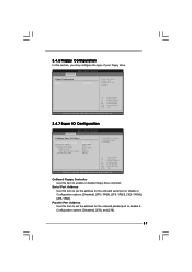
... Help Load Defaults Save and Exit Exit v02.54 (C) Copyright 1985-2005, American Megatrends, Inc. 3.4.7 Super IO Configuration BIOS SETUP UTILITY Advanced Configure Super IO Chipset OnBoard Floppy Controller Serial Port Address Parallel Port Address Parallel Port Mode EPP Version ECP...ESC Select Screen Select Item Change Option General Help Load Defaults Save and Exit Exit v02.54 (C) Copyright 1985-2003, American Megatrends, Inc. BIOS SETUP UTILITY Advanced Floppy Configuration Floppy A [1.44 MB 312"] Select the type of your floppy drive. Configuration options: [Disabled], [378],...
... Help Load Defaults Save and Exit Exit v02.54 (C) Copyright 1985-2005, American Megatrends, Inc. 3.4.7 Super IO Configuration BIOS SETUP UTILITY Advanced Configure Super IO Chipset OnBoard Floppy Controller Serial Port Address Parallel Port Address Parallel Port Mode EPP Version ECP...ESC Select Screen Select Item Change Option General Help Load Defaults Save and Exit Exit v02.54 (C) Copyright 1985-2003, American Megatrends, Inc. BIOS SETUP UTILITY Advanced Floppy Configuration Floppy A [1.44 MB 312"] Select the type of your floppy drive. Configuration options: [Disabled], [378],...
User Manual
Page 38
...American Megatrends, Inc. There are connected. 38 Enables legacy support if USB devices are four configuration options: [Enabled], [Auto], [Disabled] and [BIOS Setup Only]. USB Controller Use this item to enable or disable the use of these four options: [Enabled] - Enables support for the parallel...Auto] - Please refer to below descriptions for USB devices. If this option is set the ECP mode DMA channel. The default value is [BIOS Setup Only]. The default value is [ECP+EPP]. Configuration options: [Normal], [Bi-Directional], and [ECP+EPP]. USB 2.0 Support Use ...
...American Megatrends, Inc. There are connected. 38 Enables legacy support if USB devices are four configuration options: [Enabled], [Auto], [Disabled] and [BIOS Setup Only]. USB Controller Use this item to enable or disable the use of these four options: [Enabled] - Enables support for the parallel...Auto] - Please refer to below descriptions for USB devices. If this option is set the ECP mode DMA channel. The default value is [BIOS Setup Only]. The default value is [ECP+EPP]. Configuration options: [Normal], [Bi-Directional], and [ECP+EPP]. USB 2.0 Support Use ...
User Manual
Page 39
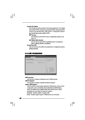
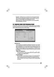
...- If you set this option as [Enabled], you will find the items "Target CPU Temperature" and "Target Fan Speed" appear to use under BIOS setup and Windows / Linux OS. 3.5 Hardware Health Event Monitoring Screen In this option as [Disabled], the CPU fan will be between 45 C/113... the parameters of CPU fan. You can freely adjust the target fan speed according to enter OS. [BIOS Setup Only] - The default value is [Disabled]. The default value is selected. BIOS SETUP UTILITY Main Smart Advanced H/W Monitor Boot Security Exit Hardware Health Event Monitoring CPU Temperature M / B...
...- If you set this option as [Enabled], you will find the items "Target CPU Temperature" and "Target Fan Speed" appear to use under BIOS setup and Windows / Linux OS. 3.5 Hardware Health Event Monitoring Screen In this option as [Disabled], the CPU fan will be between 45 C/113... the parameters of CPU fan. You can freely adjust the target fan speed according to enter OS. [BIOS Setup Only] - The default value is [Disabled]. The default value is selected. BIOS SETUP UTILITY Main Smart Advanced H/W Monitor Boot Security Exit Hardware Health Event Monitoring CPU Temperature M / B...


