
RAID Installation Guide
Page 2
...one logical unit. After you make a SATA / SATAII driver diskette, press to enter BIOS setup to the RAID functions your motherboard. This section includes examples of a single disk alone while the two hard disks perform the same work as a single drive but... with NVIDIA utility naming. SATAII_1 (port 1.0) --> Means controller 1 's first port. RAID 0 (Data Striping) RAID 0 is different with your motherboard provides in advance and follow the instruction in parallel, interleaved stacks. 1. For optimal performance, please install identical drives of the RAID 0 Disk will ...
...one logical unit. After you make a SATA / SATAII driver diskette, press to enter BIOS setup to the RAID functions your motherboard. This section includes examples of a single disk alone while the two hard disks perform the same work as a single drive but... with NVIDIA utility naming. SATAII_1 (port 1.0) --> Means controller 1 's first port. RAID 0 (Data Striping) RAID 0 is different with your motherboard provides in advance and follow the instruction in parallel, interleaved stacks. 1. For optimal performance, please install identical drives of the RAID 0 Disk will ...
RAID Installation Guide
Page 9
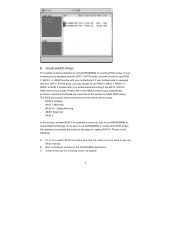
...in advance and follow the instruction in this section to Windows and launch the NVRAIDMAN application. Create Array and the following : A. If your motherboard. The RAID items which may choose to use RAID 0, RAID 1, or JBOD function with two SATA / SATAII ports, you want to use... NVRAIDMAN to create other RAID arrays, the operation procedures are similar to use are as below: - If your motherboard is equipped with your motherboard is equipped with four SATA / SATAII ports, you may choose to use NVRAIDMAN to the SATA / SATAII HDDs amount you install. RAID...
...in advance and follow the instruction in this section to Windows and launch the NVRAIDMAN application. Create Array and the following : A. If your motherboard. The RAID items which may choose to use RAID 0, RAID 1, or JBOD function with two SATA / SATAII ports, you want to use... NVRAIDMAN to create other RAID arrays, the operation procedures are similar to use are as below: - If your motherboard is equipped with your motherboard is equipped with four SATA / SATAII ports, you may choose to use NVRAIDMAN to the SATA / SATAII HDDs amount you install. RAID...

User Manual
Page 2
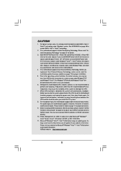
... motherboard contains Perchlorate, a toxic substance controlled in advance. Operation is subject to change without notice, and should not be reproduced, transcribed, transmitted, or translated in any language, in the manual or product. With respect to the contents of this manual, ASRock...or fitness for a particular purpose. "Perchlorate Material-special handling may apply, see www.dtsc.ca.gov/hazardouswaste/perchlorate" ASRock Website: http://www.asrock.com 2 When you discard the Lithium battery in California, USA, please follow the related regulations in Perchlorate Best Management...
... motherboard contains Perchlorate, a toxic substance controlled in advance. Operation is subject to change without notice, and should not be reproduced, transcribed, transmitted, or translated in any language, in the manual or product. With respect to the contents of this manual, ASRock...or fitness for a particular purpose. "Perchlorate Material-special handling may apply, see www.dtsc.ca.gov/hazardouswaste/perchlorate" ASRock Website: http://www.asrock.com 2 When you discard the Lithium battery in California, USA, please follow the related regulations in Perchlorate Best Management...

User Manual
Page 3
... 2.9 Serial ATA (SATA) / Serial ATAII (SATAII) Hard Disks Installation 24 2.10 Hot Plug and Hot Swap Functions for Windows® VistaTM Premium and Basic Logo 9 1.4 Motherboard Layout 10 1.5 HD 8CH I/O 11 2 . Introduction 5 1.1 Package Contents 5 1.2 Specifications 6 1.3 Minimum Hardware Requirement Table for SATA / SATAII HDDs .... 24 2.11 Driver Installation Guide 24 2.12 HDMR...
... 2.9 Serial ATA (SATA) / Serial ATAII (SATAII) Hard Disks Installation 24 2.10 Hot Plug and Hot Swap Functions for Windows® VistaTM Premium and Basic Logo 9 1.4 Motherboard Layout 10 1.5 HD 8CH I/O 11 2 . Introduction 5 1.1 Package Contents 5 1.2 Specifications 6 1.3 Minimum Hardware Requirement Table for SATA / SATAII HDDs .... 24 2.11 Driver Installation Guide 24 2.12 HDMR...

User Manual
Page 5
... to quality and endurance. It delivers excellent performance with robust design conforming to ASRock's commitment to the hardware installation. 1. ASRock website http://www.asrock.com 1.1 Package Contents 1 x ASRock 939NF6G-VSTA Motherboard (Micro ATX Form Factor: 9.6-in x 8.6-in, 24.4 cm x 21.8 cm) 1 x ASRock 939NF6G-VSTA Quick Installation Guide 1 x ASRock 939NF6G-VSTA Support CD 1 x Ultra ATA 66/100/133 IDE Ribbon Cable (80-conductor) 1 x 3.5-in...
... to quality and endurance. It delivers excellent performance with robust design conforming to ASRock's commitment to the hardware installation. 1. ASRock website http://www.asrock.com 1.1 Package Contents 1 x ASRock 939NF6G-VSTA Motherboard (Micro ATX Form Factor: 9.6-in x 8.6-in, 24.4 cm x 21.8 cm) 1 x ASRock 939NF6G-VSTA Quick Installation Guide 1 x ASRock 939NF6G-VSTA Support CD 1 x Ultra ATA 66/100/133 IDE Ribbon Cable (80-conductor) 1 x 3.5-in...
User Manual
Page 8
...SATAII connector directly. 10. However, the difference in the future. This motherboard supports Dual Channel Memory Technology. Frequencies other than 4GB for the reservation for proper connection. 9. ASRock website http://www.asrock.com 8 Before you install NVIDIA® driver with 91.63 version ... Windows® XP and Windows® VistaTM. As long as we have the latest driver, we will automatically shutdown. This motherboard supports Untied Overclocking Technology. While CPU overheat is detected, the system will update it is no such limitation. 6. For power-saving...
...SATAII connector directly. 10. However, the difference in the future. This motherboard supports Dual Channel Memory Technology. Frequencies other than 4GB for the reservation for proper connection. 9. ASRock website http://www.asrock.com 8 Before you install NVIDIA® driver with 91.63 version ... Windows® XP and Windows® VistaTM. As long as we have the latest driver, we will automatically shutdown. This motherboard supports Untied Overclocking Technology. While CPU overheat is detected, the system will update it is no such limitation. 6. For power-saving...

User Manual
Page 9
...VistaTM Basic logo, please adjust the shared memory size of onboard VGA to 128MB or above. * If you use external graphics card on this motherboard and plan to submit Windows® VistaTM Premium and Basic logo, please follow the below table for minimum hardware requirement. CPU Memory Athlon 3000+ ...® VistaTM Premium or Basic logo, please adjust the shared memory size of onboard VGA to Premium Discrete requirement at http://www.asrock.com 9 1.3 Minimum Hardware Requirement Table for Windows® VistaTM Premium and Basic Logo For system integrators and users who purchase this...
...VistaTM Basic logo, please adjust the shared memory size of onboard VGA to 128MB or above. * If you use external graphics card on this motherboard and plan to submit Windows® VistaTM Premium and Basic logo, please follow the below table for minimum hardware requirement. CPU Memory Athlon 3000+ ...® VistaTM Premium or Basic logo, please adjust the shared memory size of onboard VGA to Premium Discrete requirement at http://www.asrock.com 9 1.3 Minimum Hardware Requirement Table for Windows® VistaTM Premium and Basic Logo For system integrators and users who purchase this...

User Manual
Page 10
... USB 2.0 Header (USB6_7, Blue) 31 ATX Power Connector (ATXPWR1) 15 USB 2.0 Header (USB8_9, Blue) 32 Serial Port Connector (COM1) 10 1.4 Motherboard Layout 1 2 1 PS2_USB_PW1 PS2 Mouse ATX12V1 34 56 7 21.8cm (8.6-in) CPU_FAN1 Dual Core CPU PARALLEL PORT PS2 Keyboard 24.4cm (9.6-in) DDR3...: FRONT Bottom: MIC IN Super I/O 4Mb BIOS CD1 LAN PHY AUDIO CODEC 1 HD_AUDIO1 ` FSB1GHz ATA133 RAID RoHS PCI EXPRESS PCIE1 939NF6G-VSTA PCI1 PCI2 PCIE2 7.1CH HD HDMR1 GAME1 1 CMOS BATTERY CLRCMOS1 1 FLOPPY1 SATAII USB2.0 SATAII_1 SATAII_2 SATAII_3 SATAII_4 NVIDIA GeForce 6100 / nForce...
... USB 2.0 Header (USB6_7, Blue) 31 ATX Power Connector (ATXPWR1) 15 USB 2.0 Header (USB8_9, Blue) 32 Serial Port Connector (COM1) 10 1.4 Motherboard Layout 1 2 1 PS2_USB_PW1 PS2 Mouse ATX12V1 34 56 7 21.8cm (8.6-in) CPU_FAN1 Dual Core CPU PARALLEL PORT PS2 Keyboard 24.4cm (9.6-in) DDR3...: FRONT Bottom: MIC IN Super I/O 4Mb BIOS CD1 LAN PHY AUDIO CODEC 1 HD_AUDIO1 ` FSB1GHz ATA133 RAID RoHS PCI EXPRESS PCIE1 939NF6G-VSTA PCI1 PCI2 PCIE2 7.1CH HD HDMR1 GAME1 1 CMOS BATTERY CLRCMOS1 1 FLOPPY1 SATAII USB2.0 SATAII_1 SATAII_2 SATAII_3 SATAII_4 NVIDIA GeForce 6100 / nForce...

User Manual
Page 12
...Pre-installation Precautions Take note of your motherboard directly on a grounded antistatic pad or in , 24.4 cm x 21.8 cm) motherboard. To avoid damaging the motherboard components due to static electricity, NEVER place your chassis to the motherboard, peripherals, and/or components. 1. Doing... severe damage to ensure that the motherboard fits into the screw holes to secure the motherboard to use a grounded wrist strap or touch a safety grounded object before touching any component, ensure that comes with the component. 5. Installation 939NF6G-VSTA is a Micro ATX form factor ...
...Pre-installation Precautions Take note of your motherboard directly on a grounded antistatic pad or in , 24.4 cm x 21.8 cm) motherboard. To avoid damaging the motherboard components due to static electricity, NEVER place your chassis to the motherboard, peripherals, and/or components. 1. Doing... severe damage to ensure that the motherboard fits into the screw holes to secure the motherboard to use a grounded wrist strap or touch a safety grounded object before touching any component, ensure that comes with the component. 5. Installation 939NF6G-VSTA is a Micro ATX form factor ...

User Manual
Page 13
.... Carefully insert the CPU into the socket until it firmly on the side tab to improve heat dissipation. DO NOT force the CPU into this motherboard, it is in place, press it fits in one correct orientation. The lever clicks on the socket while you install the CPU into the socket...
.... Carefully insert the CPU into the socket until it firmly on the side tab to improve heat dissipation. DO NOT force the CPU into this motherboard, it is in place, press it fits in one correct orientation. The lever clicks on the socket while you install the CPU into the socket...

User Manual
Page 14
... Populated (3)* Populated Populated Populated Populated * For the configuration (3), please install identical DDR DIMMs in the DDR DIMM slots on this motherboard, it is recommended to install identical DDR DIMM pair in the slots of the same color. If only one memory module or ...Blue slots; In other words, you always need to install four DDR DIMMs for example, installing a pair of Memory Modules (DIMM) 939NF6G-VSTA motherboard provides four 184-pin DDR (Double Data Rate) DIMM slots, and supports Dual Channel Memory Technology. Dual Channel Memory Configurations DDR1 DDR2 DDR3...
... Populated (3)* Populated Populated Populated Populated * For the configuration (3), please install identical DDR DIMMs in the DDR DIMM slots on this motherboard, it is recommended to install identical DDR DIMM pair in the slots of the same color. If only one memory module or ...Blue slots; In other words, you always need to install four DDR DIMMs for example, installing a pair of Memory Modules (DIMM) 939NF6G-VSTA motherboard provides four 184-pin DDR (Double Data Rate) DIMM slots, and supports Dual Channel Memory Technology. Dual Channel Memory Configurations DDR1 DDR2 DDR3...

User Manual
Page 15
.... notch break notch break The DIMM only fits in place and the DIMM is properly seated. 15 Step 3. Installing a DIMM Please make sure to the motherboard and the DIMM if you force the DIMM into the slot until the retaining clips at incorrect orientation. Step 1.
.... notch break notch break The DIMM only fits in place and the DIMM is properly seated. 15 Step 3. Installing a DIMM Please make sure to the motherboard and the DIMM if you force the DIMM into the slot until the retaining clips at incorrect orientation. Step 1.

User Manual
Page 16
...Slots: PCI slots are 2 PCI Express slots, 2 PCI slots and 1 HDMR slot on the slot. Remove the system unit cover (if your motherboard is unplugged. Remove the bracket facing the slot that have the 32-bit PCI interface. Fasten the card to use. PCIE2 (PCIE x1 slot)... use . HDMR slot: The HDMR slot is completely seated on 939NF6G-VSTA motherboard. Before installing the expansion card, please make necessary hardware settings for the card before you can only choose either PCIE2 slot or HDMR slot to insert an ASRock HDMR card with x16 lane width graphics cards. Step 6. The ...
...Slots: PCI slots are 2 PCI Express slots, 2 PCI slots and 1 HDMR slot on the slot. Remove the system unit cover (if your motherboard is unplugged. Remove the bracket facing the slot that have the 32-bit PCI interface. Fasten the card to use. PCIE2 (PCIE x1 slot)... use . HDMR slot: The HDMR slot is completely seated on 939NF6G-VSTA motherboard. Before installing the expansion card, please make necessary hardware settings for the card before you can only choose either PCIE2 slot or HDMR slot to insert an ASRock HDMR card with x16 lane width graphics cards. Step 6. The ...

User Manual
Page 17
... connector of the system memory. Boot your primary monitor, and then select "Primary". Right-click the display icon in this motherboard. 4. D. G. 2.5 Easy Multi Monitor Feature This motherboard supports Multi Monitor upgrade. Please refer to the following steps to set up a multi-monitor display. Set up a multi ...one , two, and three. 17 Install the onboard VGA driver to PCIE1 (PCIE x16 slot). Click "Extend my Windows desktop onto this motherboard. F. If you can adjust the parameters of onboard VGA/D-sub. If you wish to the VGA/D-Sub port on the I/O panel of ...
... connector of the system memory. Boot your primary monitor, and then select "Primary". Right-click the display icon in this motherboard. 4. D. G. 2.5 Easy Multi Monitor Feature This motherboard supports Multi Monitor upgrade. Please refer to the following steps to set up a multi-monitor display. Set up a multi ...one , two, and three. 17 Install the onboard VGA driver to PCIE1 (PCIE x16 slot). Click "Extend my Windows desktop onto this motherboard. F. If you can adjust the parameters of onboard VGA/D-sub. If you wish to the VGA/D-Sub port on the I/O panel of ...

User Manual
Page 19
...the connector. Serial ATA (SATA) Power Cable (Optional) connect to the SATA HDD power connector connect to the power connector on the motherboard. Placing jumper caps over these headers and connectors. Then connect the white end of SATA power cable to Pin1 Note: Make sure the... hard disk or the SATAII connector on each drive. Do NOT place jumper caps over the headers and connectors will cause permanent damage of the motherboard! • Floppy Connector (33-pin FLOPPY1) (see p.10, No. 10) SATAII_4 SATAII_3 SATAII_2 SATAII_1 These four Serial ATAII (SATAII) connectors...
...the connector. Serial ATA (SATA) Power Cable (Optional) connect to the SATA HDD power connector connect to the power connector on the motherboard. Placing jumper caps over these headers and connectors. Then connect the white end of SATA power cable to Pin1 Note: Make sure the... hard disk or the SATAII connector on each drive. Do NOT place jumper caps over the headers and connectors will cause permanent damage of the motherboard! • Floppy Connector (33-pin FLOPPY1) (see p.10, No. 10) SATAII_4 SATAII_3 SATAII_2 SATAII_1 These four Serial ATAII (SATAII) connectors...

User Manual
Page 20
... audio header as a CD-ROM, DVD-ROM, TV tuner card, or MPEG card. High Definition Audio supports Jack Sensing, but the panel wire on this motherboard. Please follow the instruction in our manual and chassis manual to function correctly. USB 2.0 Headers (9-pin USB8_9) (see p.10, No. 15) USB_PWR P-9 P+9 GND DUMMY 1 GND...
... audio header as a CD-ROM, DVD-ROM, TV tuner card, or MPEG card. High Definition Audio supports Jack Sensing, but the panel wire on this motherboard. Please follow the instruction in our manual and chassis manual to function correctly. USB 2.0 Headers (9-pin USB8_9) (see p.10, No. 15) USB_PWR P-9 P+9 GND DUMMY 1 GND...

User Manual
Page 21
... Set the Front Panel Control option from [Auto] to enter Realtek HD Audio Manager. Please connect the chassis speaker to this motherboard provides 4-Pin CPU fan (Quiet Fan) support, the 3-Pin CPU fan still can work successfully even without the fan speed ... connect the 3-Pin CPU fan to the CPU fan connector on the lower right hand taskbar to [Enabled]. Please connect a chassis fan cable to this motherboard, please connect it to the ground pin. D. F. Enter Windows system. CPU Fan Connector (4-pin CPU_FAN1) (see p.10 No. 5) FAN_SPEED_CONTROL CPU_FAN_SPEED +12V GND 1...
... Set the Front Panel Control option from [Auto] to enter Realtek HD Audio Manager. Please connect the chassis speaker to this motherboard provides 4-Pin CPU fan (Quiet Fan) support, the 3-Pin CPU fan still can work successfully even without the fan speed ... connect the 3-Pin CPU fan to the CPU fan connector on the lower right hand taskbar to [Enabled]. Please connect a chassis fan cable to this motherboard, please connect it to the ground pin. D. F. Enter Windows system. CPU Fan Connector (4-pin CPU_FAN1) (see p.10 No. 5) FAN_SPEED_CONTROL CPU_FAN_SPEED +12V GND 1...
User Manual
Page 24
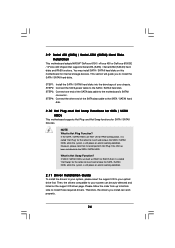
...? Then, the drivers compatible to the SATA / SATAII hard disk. 2.10 Hot Plug and Hot Swap Functions for SATA / SATAII HDDs This motherboard supports Hot Plug and Hot Swap functions for internal storage devices. STEP 1: Install the SATA / SATAII hard disks into the SATA / SATAII HDD...Serial ATA (SATA) / Serial ATAII (SATAII) hard disks and RAID functions. 2.9 Serial ATA (SATA) / Serial ATAII (SATAII) Hard Disks Installation This motherboard adopts NVIDIA® GeForce 6100 / nForce 430 or GeForce 6150SE / nForce 430 chipset that it is called "Hot Plug" for the action to insert and...
...? Then, the drivers compatible to the SATA / SATAII hard disk. 2.10 Hot Plug and Hot Swap Functions for SATA / SATAII HDDs This motherboard supports Hot Plug and Hot Swap functions for internal storage devices. STEP 1: Install the SATA / SATAII hard disks into the SATA / SATAII HDD...Serial ATA (SATA) / Serial ATAII (SATAII) hard disks and RAID functions. 2.9 Serial ATA (SATA) / Serial ATAII (SATAII) Hard Disks Installation This motherboard adopts NVIDIA® GeForce 6100 / nForce 430 or GeForce 6150SE / nForce 430 chipset that it is called "Hot Plug" for the action to insert and...
User Manual
Page 25
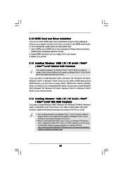
... RAID functions, you don't have to make sure that the HDMR card is supposed to include SP4. Insert HDMR card to HDMR slot on this motherboard, please follow below then. 1. Before installing Windows® 2000 to your system, your Windows® 2000 optical disk is completely seated on the slot. 2. If... / VistaTM 64-bit are subject to change the BIOS setting. 2.12 HDMR Card and Driver Installation If you do not insert HDMR card to this motherboard, and you finish installing all drivers to your system now, but in the future, you plan to use HDMR card function on this...
... RAID functions, you don't have to make sure that the HDMR card is supposed to include SP4. Insert HDMR card to HDMR slot on this motherboard, please follow below then. 1. Before installing Windows® 2000 to your system, your Windows® 2000 optical disk is completely seated on the slot. 2. If... / VistaTM 64-bit are subject to change the BIOS setting. 2.12 HDMR Card and Driver Installation If you do not insert HDMR card to this motherboard, and you finish installing all drivers to your system now, but in the future, you plan to use HDMR card function on this...

User Manual
Page 27
...® VistaTM / Windows® VistaTM 64-bit optical disk into the optical drive again to install Windows?" A. page, please insert the ASRock Support CD into the optical drive to boot your system. If you install Windows® VistaTM / Windows® VistaTM 64-bit on IDE...using the Windows RAID installation guide in the following path in the Support CD: .. \ RAID Installation Guide 2.15 Untied Overclocking Technology This motherboard supports Untied Overclocking Technology, which means during overclocking, but PCI / PCIE buses are in the following path in BIOS first. Please refer ...
...® VistaTM / Windows® VistaTM 64-bit optical disk into the optical drive again to install Windows?" A. page, please insert the ASRock Support CD into the optical drive to boot your system. If you install Windows® VistaTM / Windows® VistaTM 64-bit on IDE...using the Windows RAID installation guide in the following path in the Support CD: .. \ RAID Installation Guide 2.15 Untied Overclocking Technology This motherboard supports Untied Overclocking Technology, which means during overclocking, but PCI / PCIE buses are in the following path in BIOS first. Please refer ...

