User Manual
Page 3
Installation 10 Pre-installation Precautions 10 2.1 CPU Installation 11 2.2 Installation of CPU Fan and Heatsink 11 2.3 Installation of Memory Modules (DIMM 12 2.4 Expansion Slots (PCI and AGP Slots 14 2.5 Jumpers Setup... For SATA Operation in "RAID" Mode 20 2.9 SATA Operating in "non-RAID" Mode 20 3 . Introduction 5 1.1 Package Contents 5 1.2 Specifications 6 1.3 Motherboard Layout 8 1.4 ASRock 8CH I/O 9 2 . BIOS SETUP UTILITY 21 3.1 Introduction 21 3.1.1 BIOS Menu Bar 21 3.1.2 Navigation Keys 22 3.2 Main Screen 22 3.3 Advanced Screen 23 3.3.1 CPU Configuration 23 ...
Installation 10 Pre-installation Precautions 10 2.1 CPU Installation 11 2.2 Installation of CPU Fan and Heatsink 11 2.3 Installation of Memory Modules (DIMM 12 2.4 Expansion Slots (PCI and AGP Slots 14 2.5 Jumpers Setup... For SATA Operation in "RAID" Mode 20 2.9 SATA Operating in "non-RAID" Mode 20 3 . Introduction 5 1.1 Package Contents 5 1.2 Specifications 6 1.3 Motherboard Layout 8 1.4 ASRock 8CH I/O 9 2 . BIOS SETUP UTILITY 21 3.1 Introduction 21 3.1.1 BIOS Menu Bar 21 3.1.2 Navigation Keys 22 3.2 Main Screen 22 3.3 Advanced Screen 23 3.3.1 CPU Configuration 23 ...
User Manual
Page 6
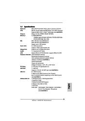
... (10/100 Ethernet), supports Wake-On-LAN Hardware Monitor: CPU temperature sensing Motherboard temperature sensing CPU overheat shutdown to protect CPU life (ASRock U-COP)(see CAUTION 2) CPU fan tachometer Chassis fan tachometer Voltage monitoring: +12V, +5V, +3.3V, Vcore PCI Slots: 3 x PCI slots, PCI specification 2.3 AGP Slot: 1 x AGP slot Supports 1.5V, 8X / 4X AGP...
... (10/100 Ethernet), supports Wake-On-LAN Hardware Monitor: CPU temperature sensing Motherboard temperature sensing CPU overheat shutdown to protect CPU life (ASRock U-COP)(see CAUTION 2) CPU fan tachometer Chassis fan tachometer Voltage monitoring: +12V, +5V, +3.3V, Vcore PCI Slots: 3 x PCI slots, PCI specification 2.3 AGP Slot: 1 x AGP slot Supports 1.5V, 8X / 4X AGP...
User Manual
Page 7
.... 6. See APPENDIX on page 37 to spray thermal grease between the CPU and the heatsink when you resume the system, please check if the CPU fan on page 9 for advanced users' reference, see CAUTION 6) Microsoft® Windows® 98SE / ME / 2000 / XP compliant CAUTION! 1. For audio output, this motherboard supports mono...
.... 6. See APPENDIX on page 37 to spray thermal grease between the CPU and the heatsink when you resume the system, please check if the CPU fan on page 9 for advanced users' reference, see CAUTION 6) Microsoft® Windows® 98SE / ME / 2000 / XP compliant CAUTION! 1. For audio output, this motherboard supports mono...
User Manual
Page 11
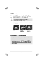
... the golden triangle matches the socket corner with each other. When the CPU is in good contact with a small triangle. Then connect the CPU fan to avoid bending of the pins. You also need to spray thermal grease between the CPU and the heatsink to the instruction manuals of CPU... Corner STEP 2 / STEP 3: STEP 4: Match The CPU Golden Triangle Push Down And Lock To The Socket Corner The Socket Lever 2.2 Installation of the CPU fan and the heatsink. 11 Carefully insert the CPU into this motherboard, it firmly on the side tab to secure the CPU. Make sure that it...
... the golden triangle matches the socket corner with each other. When the CPU is in good contact with a small triangle. Then connect the CPU fan to avoid bending of the pins. You also need to spray thermal grease between the CPU and the heatsink to the instruction manuals of CPU... Corner STEP 2 / STEP 3: STEP 4: Match The CPU Golden Triangle Push Down And Lock To The Socket Corner The Socket Lever 2.2 Installation of the CPU fan and the heatsink. 11 Carefully insert the CPU into this motherboard, it firmly on the side tab to secure the CPU. Make sure that it...

User Manual
Page 18
...Panel Connector (9-pin PANEL1) (see p.8 item 12) Chassis Speaker Connector pin SPEAKER 1) (see p.8 item 11) GND +12V CHA_FAN_SPEED Please connect a chassis fan cable to this connector. ATX 12V Connector (4-pin ATX12V1) (see p.8 item 28) Game Connector (15-pin GAME1) (see p.8 item 25) Please connect... that it can provides sufficient power. Please connect the chassis ( 4 speaker to this connector and match the black wire to power up. Chassis Fan Connector (3-pin CHA_FAN1) (see p.8 item 13) PLED+ PLEDPWRBTN# GND 1 DUMMY RESET# GND HDLEDHDLED+ 1 SPEAKER DUMMY DUMMY +5V This connector...
...Panel Connector (9-pin PANEL1) (see p.8 item 12) Chassis Speaker Connector pin SPEAKER 1) (see p.8 item 11) GND +12V CHA_FAN_SPEED Please connect a chassis fan cable to this connector. ATX 12V Connector (4-pin ATX12V1) (see p.8 item 28) Game Connector (15-pin GAME1) (see p.8 item 25) Please connect... that it can provides sufficient power. Please connect the chassis ( 4 speaker to this connector and match the black wire to power up. Chassis Fan Connector (3-pin CHA_FAN1) (see p.8 item 13) PLED+ PLEDPWRBTN# GND 1 DUMMY RESET# GND HDLEDHDLED+ 1 SPEAKER DUMMY DUMMY +5V This connector...
User Manual
Page 33
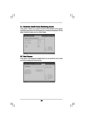
... Floppy Device] Configure Settings during System Boot. BIOS SETUP UTILITY Main Advanced H/W Monitor Boot Security Exit Hardware Health Event Monitoring CPU Temperature M / B Temperature CPU Fan Speed Chassis Fan Speed Vcore + 3.30V + 5.00V + 12.00V : 37 C / 98 F : 31 C / 87 F : 2833 RPM : N/A : 1.532 V : 3.129 V : 4.877 V : 11.741 V F1 F9 F10 ESC Select Screen ...this section, it allows you to monitor the status of the hardware on your system, including the parameters of the CPU temperature, motherboard temperature, CPU fan speed, chassis fan speed, and the critical voltage.
... Floppy Device] Configure Settings during System Boot. BIOS SETUP UTILITY Main Advanced H/W Monitor Boot Security Exit Hardware Health Event Monitoring CPU Temperature M / B Temperature CPU Fan Speed Chassis Fan Speed Vcore + 3.30V + 5.00V + 12.00V : 37 C / 98 F : 31 C / 87 F : 2833 RPM : N/A : 1.532 V : 3.129 V : 4.877 V : 11.741 V F1 F9 F10 ESC Select Screen ...this section, it allows you to monitor the status of the hardware on your system, including the parameters of the CPU temperature, motherboard temperature, CPU fan speed, chassis fan speed, and the critical voltage.
Quick Installation Guide
Page 2
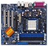
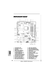
...) 8 Secondary IDE Connector (IDE2, Black) 9 Primary IDE Connector (IDE1, Blue) 10 Clear CMOS Jumper (CLRTC1) 11 Chassis Fan Connector (CHA_FAN1) 12 System Panel Header (PANEL1) 13 Chassis Speaker Header (SPEAKER 1) 14 USB 2.0 Header (USB67, Blue) 15...ATXPWR1) 26 CPU Heatsink Retention Module 27 939-Pin CPU Socket 28 ATX 12V Connector (ATX12V1) 2 ASRock 939A8X-M Motherboard Motherboard Layout English 1 PS2_USB_PWR1 Jumper 2 Infrared Module Header (IR1) 3 Flash Memory 4 Floppy Connector (FLOPPY1) 5 CPU Fan Connector (CPU_FAN1) 6 2 x 184-pin DDR DIMM Slots (Dual Channel A: DDR1, DDR2; Blue...
...) 8 Secondary IDE Connector (IDE2, Black) 9 Primary IDE Connector (IDE1, Blue) 10 Clear CMOS Jumper (CLRTC1) 11 Chassis Fan Connector (CHA_FAN1) 12 System Panel Header (PANEL1) 13 Chassis Speaker Header (SPEAKER 1) 14 USB 2.0 Header (USB67, Blue) 15...ATXPWR1) 26 CPU Heatsink Retention Module 27 939-Pin CPU Socket 28 ATX 12V Connector (ATX12V1) 2 ASRock 939A8X-M Motherboard Motherboard Layout English 1 PS2_USB_PWR1 Jumper 2 Infrared Module Header (IR1) 3 Flash Memory 4 Floppy Connector (FLOPPY1) 5 CPU Fan Connector (CPU_FAN1) 6 2 x 184-pin DDR DIMM Slots (Dual Channel A: DDR1, DDR2; Blue...
Quick Installation Guide
Page 5
...supports Wake-On-LAN Hardware Monitor: CPU temperature sensing Motherboard temperature sensing CPU overheat shutdown to protect CPU life (ASRock U-COP)(see CAUTION 2) CPU fan tachometer Chassis fan tachometer Voltage monitoring: +12V, +5V, +3.3V, Vcore PCI Slots: 3 x PCI slots, PCI specification ...ASRock 8CH I/O: 1 PS/2 Mouse Port, 1 PS/2 Keyboard Port 1 Serial Port: COM1 1 Parallel Port (ECP/EPP Support) 4 Ready-to-Use USB 2.0 Ports 1 RJ-45 Port Audio Jack: Side Speaker / Rear Speaker / Central/Bass / Line In / Front Speaker / Microphone (see CAUTION 5) English 5 ASRock 939A8X...
...supports Wake-On-LAN Hardware Monitor: CPU temperature sensing Motherboard temperature sensing CPU overheat shutdown to protect CPU life (ASRock U-COP)(see CAUTION 2) CPU fan tachometer Chassis fan tachometer Voltage monitoring: +12V, +5V, +3.3V, Vcore PCI Slots: 3 x PCI slots, PCI specification ...ASRock 8CH I/O: 1 PS/2 Mouse Port, 1 PS/2 Keyboard Port 1 Serial Port: COM1 1 Parallel Port (ECP/EPP Support) 4 Ready-to-Use USB 2.0 Ports 1 RJ-45 Port Audio Jack: Side Speaker / Rear Speaker / Central/Bass / Line In / Front Speaker / Microphone (see CAUTION 5) English 5 ASRock 939A8X...
Quick Installation Guide
Page 6
...ME. 5. It may cause permanent damage! 4. Before you install the PC system. 3. For audio output, this motherboard supports mono modes. English 6 ASRock 939A8X-M Motherboard Please check the table on the AGP slot of the system or damage the CPU. Power Management for advanced users' reference, see CAUTION 6)... is strongly recommended to spray thermal grease between the CPU and the heatsink when you resume the system, please check if the CPU fan on page 37 of "User Manual" in the Support CD to perform over-clocking. For microphone input, this motherboard supports 2-channel,...
...ME. 5. It may cause permanent damage! 4. Before you install the PC system. 3. For audio output, this motherboard supports mono modes. English 6 ASRock 939A8X-M Motherboard Please check the table on the AGP slot of the system or damage the CPU. Power Management for advanced users' reference, see CAUTION 6)... is strongly recommended to spray thermal grease between the CPU and the heatsink when you resume the system, please check if the CPU fan on page 37 of "User Manual" in the Support CD to perform over-clocking. For microphone input, this motherboard supports 2-channel,...
Quick Installation Guide
Page 7
... comes with the component. 5. Step 5. The lever clicks on the side tab to static electricity, NEVER place your CPU fan and heatsink vendors. English 7 ASRock 939A8X-M Motherboard 2. When placing screws into the socket until it fits in place, press it firmly on the socket while you ... that its marked corner matches the base of the following precautions before you install motherboard components or change any component. Install CPU fan and heatsink. Doing so may cause severe damage to secure the CPU. When the CPU is locked. Installation Pre-installation Precautions ...
... comes with the component. 5. Step 5. The lever clicks on the side tab to static electricity, NEVER place your CPU fan and heatsink vendors. English 7 ASRock 939A8X-M Motherboard 2. When placing screws into the socket until it fits in place, press it firmly on the socket while you ... that its marked corner matches the base of the following precautions before you install motherboard components or change any component. Install CPU fan and heatsink. Doing so may cause severe damage to secure the CPU. When the CPU is locked. Installation Pre-installation Precautions ...

Quick Installation Guide
Page 14
... pin. Failing to do so will cause the failure to this connector. Please connect a CPU fan cable to this connector and match the black wire to the ground pin. Please note that it is installed. English 14 ASRock 939A8X-M Motherboard Please connect an ATX power supply to this connector. Connect a Game cable to...
... pin. Failing to do so will cause the failure to this connector. Please connect a CPU fan cable to this connector and match the black wire to the ground pin. Please note that it is installed. English 14 ASRock 939A8X-M Motherboard Please connect an ATX power supply to this connector. Connect a Game cable to...


