User Manual
Page 2
... this device must accept any interference received, including interference that may apply, see www.dtsc.ca.gov/hazardouswaste/perchlorate" ASRock Website: http://www.asrock.com 2 Copyright Notice: No part of this manual may be reproduced, transcribed, transmitted, or translated in any language... or fitness for a particular purpose. This device complies with Part 15 of ASRock Inc. Operation is subject to infringe. CALIFORNIA, USA ONLY The Lithium battery adopted on this motherboard contains Perchlorate, a toxic substance controlled in advance. When you discard the Lithium...
... this device must accept any interference received, including interference that may apply, see www.dtsc.ca.gov/hazardouswaste/perchlorate" ASRock Website: http://www.asrock.com 2 Copyright Notice: No part of this manual may be reproduced, transcribed, transmitted, or translated in any language... or fitness for a particular purpose. This device complies with Part 15 of ASRock Inc. Operation is subject to infringe. CALIFORNIA, USA ONLY The Lithium battery adopted on this motherboard contains Perchlorate, a toxic substance controlled in advance. When you discard the Lithium...
User Manual
Page 3
... Functions 34 2.15.2 Installing Windows® 7 / 7 64-bit / VistaTM / VistaTM 64-bit Without RAID Functions 35 2.16 Untied Overclocking Technology 36 3 Introduction 5 1.1 Package Contents 5 1.2 Specifications 6 1.3 Motherboard Layout 11 1.4 I/O Panel 12 2 . Contents 1 .
... Functions 34 2.15.2 Installing Windows® 7 / 7 64-bit / VistaTM / VistaTM 64-bit Without RAID Functions 35 2.16 Untied Overclocking Technology 36 3 Introduction 5 1.1 Package Contents 5 1.2 Specifications 6 1.3 Motherboard Layout 11 1.4 I/O Panel 12 2 . Contents 1 .
User Manual
Page 5
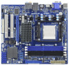
... the configuration guide to BIOS setup and information of the motherboard and step-by-step guide to change without further notice. www.asrock.com/support/index.asp 1.1 Package Contents ASRock 939A790GMH Motherboard (Micro ATX Form Factor: 9.6-in x 8.6-in, 24.4 cm x 21.8 cm) ASRock 939A790GMH Quick Installation Guide ASRock 939A790GMH Support CD 1 x Ultra ATA 66/100/133 IDE Ribbon Cable...
... the configuration guide to BIOS setup and information of the motherboard and step-by-step guide to change without further notice. www.asrock.com/support/index.asp 1.1 Package Contents ASRock 939A790GMH Motherboard (Micro ATX Form Factor: 9.6-in x 8.6-in, 24.4 cm x 21.8 cm) ASRock 939A790GMH Quick Installation Guide ASRock 939A790GMH Support CD 1 x Ultra ATA 66/100/133 IDE Ribbon Cable...

User Manual
Page 8
... connect SATA hard disk to SATAII connector, please read the installation guide of ASRock OC Tuner. Voltage Monitoring: +12V, +5V, +3.3V, Vcore OS - This motherboard supports Dual Channel Memory Technology. This motherboard supports Untied Overclocking Technology. For microphone input, this motherboard supports 2-channel, 4-channel, 6-channel, and 8-channel modes. Chassis Temperature Sensing - FCC, CE, WHQL...
... connect SATA hard disk to SATAII connector, please read the installation guide of ASRock OC Tuner. Voltage Monitoring: +12V, +5V, +3.3V, Vcore OS - This motherboard supports Dual Channel Memory Technology. This motherboard supports Untied Overclocking Technology. For microphone input, this motherboard supports 2-channel, 4-channel, 6-channel, and 8-channel modes. Chassis Temperature Sensing - FCC, CE, WHQL...
User Manual
Page 9
... website regularly, we will continuously provide you can reduce the number of PC gaming operation. ASRock Instant Flash is just to install the ASRock AIWI utility either from ASRock official website or ASRock software support CD to your motherboard, and also download the free AIWI Lite from App store to provide exceptional power saving and...
... website regularly, we will continuously provide you can reduce the number of PC gaming operation. ASRock Instant Flash is just to install the ASRock AIWI utility either from ASRock official website or ASRock software support CD to your motherboard, and also download the free AIWI Lite from App store to provide exceptional power saving and...

User Manual
Page 10
... prepared a wonderful solution for you checking with the power supply manufacturer for more details. 10 ASRock APP Charger allows you resume the system, please check if the CPU fan on the motherboard functions properly and unplug the power cord, then plug it makes your iPhone charged much quickly... from your PC enters into Standby mode (S1), Suspend to RAM (S3), hibernation mode (S4) or power off mode condition. ASRock website: http://www.asrock.com/Feature/AppCharger/...
... prepared a wonderful solution for you checking with the power supply manufacturer for more details. 10 ASRock APP Charger allows you resume the system, please check if the CPU fan on the motherboard functions properly and unplug the power cord, then plug it makes your iPhone charged much quickly... from your PC enters into Standby mode (S1), Suspend to RAM (S3), hibernation mode (S4) or power off mode condition. ASRock website: http://www.asrock.com/Feature/AppCharger/...

User Manual
Page 13
... on the carpet or the like. Doing so may cause severe damage to the chassis, please do not touch the ICs. 4. Installation 939A790GMH is detached from the wall socket before touching any component, ensure that the power is switched off or the power cord is a Micro ...ATX form factor (9.6-in x 8.6-in the bag that the motherboard fits into the screw holes to secure the motherboard to the motherboard, peripherals, and/or components. 1. Failure to do so may damage the motherboard. 13 Also remember to ensure that comes with the component. 5. Pre-installation ...
... on the carpet or the like. Doing so may cause severe damage to the chassis, please do not touch the ICs. 4. Installation 939A790GMH is detached from the wall socket before touching any component, ensure that the power is switched off or the power cord is a Micro ...ATX form factor (9.6-in x 8.6-in the bag that the motherboard fits into the screw holes to secure the motherboard to the motherboard, peripherals, and/or components. 1. Failure to do so may damage the motherboard. 13 Also remember to ensure that comes with the component. 5. Pre-installation ...
User Manual
Page 14
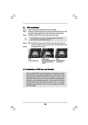
... place. The lever clicks on the socket while you install the CPU into the socket to dissipate heat. DO NOT force the CPU into this motherboard, it firmly on the side tab to secure the CPU. Lever 90° Up CPU Golden Triangle STEP 1: Lift Up The Socket Lever Socket Corner...
... place. The lever clicks on the socket while you install the CPU into the socket to dissipate heat. DO NOT force the CPU into this motherboard, it firmly on the side tab to secure the CPU. Lever 90° Up CPU Golden Triangle STEP 1: Lift Up The Socket Lever Socket Corner...

User Manual
Page 15
... words, install them in all four slots. 1. see p.11 No.6) or identical DDR DIMM pair in the DDR DIMM slots on this motherboard, it is unable to the Dual Channel Memory Configuration Table below. In other words, you want to install two memory modules, for optimal ...compatibility and reliability, it is recommended to install identical DDR DIMM pair in the set of Memory Modules (DIMM) 939A790GMH motherboard provides four 184-pin DDR (Double Data Rate) DIMM slots, and supports Dual Channel Memory Technology. see p.11 No.7), so that Dual ...
... words, install them in all four slots. 1. see p.11 No.6) or identical DDR DIMM pair in the DDR DIMM slots on this motherboard, it is unable to the Dual Channel Memory Configuration Table below. In other words, you want to install two memory modules, for optimal ...compatibility and reliability, it is recommended to install identical DDR DIMM pair in the set of Memory Modules (DIMM) 939A790GMH motherboard provides four 184-pin DDR (Double Data Rate) DIMM slots, and supports Dual Channel Memory Technology. see p.11 No.7), so that Dual ...

User Manual
Page 16
... outward. Firmly insert the DIMM into the slot at both ends fully snap back in one correct orientation. Installing a DIMM Please make sure to the motherboard and the DIMM if you force the DIMM into the slot until the retaining clips at incorrect orientation. Step 3. Step 2. notch break notch break The...
... outward. Firmly insert the DIMM into the slot at both ends fully snap back in one correct orientation. Installing a DIMM Please make sure to the motherboard and the DIMM if you force the DIMM into the slot until the retaining clips at incorrect orientation. Step 3. Step 2. notch break notch break The...

User Manual
Page 17
Blue) is completely seated on this motherboard. Remove the bracket facing the slot that you start the installation. Align the card connector with the slot and press firmly until the card is ...
Blue) is completely seated on this motherboard. Remove the bracket facing the slot that you start the installation. Align the card connector with the slot and press firmly until the card is ...
User Manual
Page 18
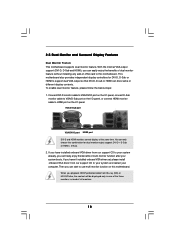
...the benefits of all monitors. 18 2.5 Dual Monitor and Surround Display Features Dual Monitor Feature This motherboard supports dual monitor feature. To enable dual monitor feature, please follow the below steps: 1. This motherboard also provides independent display controllers for dual monitor output support: DVI-D + D-Sub or HDMI +...one of the three monitors instead of dual monitor feature without installing any add-on VGA card to HDMI port on this motherboard. If you playback HDCP-protected video from our support CD to support dual VGA output so that DVI-D, D-sub or HDMI...
...the benefits of all monitors. 18 2.5 Dual Monitor and Surround Display Features Dual Monitor Feature This motherboard supports dual monitor feature. To enable dual monitor feature, please follow the below steps: 1. This motherboard also provides independent display controllers for dual monitor output support: DVI-D + D-Sub or HDMI +...one of the three monitors instead of dual monitor feature without installing any add-on VGA card to HDMI port on this motherboard. If you playback HDCP-protected video from our support CD to support dual VGA output so that DVI-D, D-sub or HDMI...
User Manual
Page 19
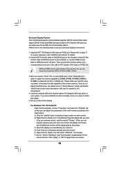
.... 2. Set up a surround display environment: 1. B. Select the display icon identified by the number 2. Click "Extend my Windows desktop onto this motherboard. 4. Connect DVI-D monitor cable to VGA/DVI-D port on the I/O panel, connect D-Sub monitor cable to VGA/D-Sub port on the I/O panel...you select is inserted to this monitor". Right-click the display icon and select "Attached", if necessary. Surround Display Feature This motherboard supports surround display upgrade. Install the ATITM PCI Express VGA cards on PCI Express VGA card, you have installed the drivers already,...
.... 2. Set up a surround display environment: 1. B. Select the display icon identified by the number 2. Click "Extend my Windows desktop onto this motherboard. 4. Connect DVI-D monitor cable to VGA/DVI-D port on the I/O panel, connect D-Sub monitor cable to VGA/D-Sub port on the I/O panel...you select is inserted to this monitor". Right-click the display icon and select "Attached", if necessary. Surround Display Feature This motherboard supports surround display upgrade. Install the ATITM PCI Express VGA cards on PCI Express VGA card, you have installed the drivers already,...

User Manual
Page 20
..., HDCP specification is designed to protect the integrity of content as it is highly recommended that you purchase is supported on this motherboard, you can enjoy the superior display quality with the HDCP scheme such as few entertainment PCs requires a secure connection to positions... representing the physical setup of your change. Due to use HDCP function with this motherboard. For Windows® 7 / 7 64-bit / VistaTM / VistaTM 64-bit OS: Right click the desktop, choose "Personalize", and select the...
..., HDCP specification is designed to protect the integrity of content as it is highly recommended that you purchase is supported on this motherboard, you can enjoy the superior display quality with the HDCP scheme such as few entertainment PCs requires a secure connection to positions... representing the physical setup of your change. Due to use HDCP function with this motherboard. For Windows® 7 / 7 64-bit / VistaTM / VistaTM 64-bit OS: Right click the desktop, choose "Personalize", and select the...
User Manual
Page 21
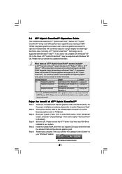
...to your computer. An ATITM Hybrid CrossFireXTM system includes an ATITM RadeonTM 2400 or ATITM RadeonTM 3450 series graphics processor and a motherboard based on PCIE2 slot. Please visit our website for updated information. Install the onboard VGA driver from our support CD to...and the discrete graphics card. Step 2. Boot your system. ATI Catalyst Control Center 21 2.6 ATITM Hybrid CrossFireXTM Operation Guide This motherboard supports ATITM Hybrid CrossFireXTM feature. In the future, ATITM Hybrid CrossFireXTM may be supported with combined output to [Enabled]. Please refer ...
...to your computer. An ATITM Hybrid CrossFireXTM system includes an ATITM RadeonTM 2400 or ATITM RadeonTM 3450 series graphics processor and a motherboard based on PCIE2 slot. Please visit our website for updated information. Install the onboard VGA driver from our support CD to...and the discrete graphics card. Step 2. Boot your system. ATI Catalyst Control Center 21 2.6 ATITM Hybrid CrossFireXTM Operation Guide This motherboard supports ATITM Hybrid CrossFireXTM feature. In the future, ATITM Hybrid CrossFireXTM may be supported with combined output to [Enabled]. Please refer ...

User Manual
Page 24
... these headers and connectors. Primary IDE connector (Blue) (39-pin IDE1, see p.11 No. 9) PIN1 IDE1 connect the blue end to the motherboard connect the black end to the IDE devices 80-conductor ATA 66/100/133 cable Note: Please refer to the SATA / SATAII hard disk or... The current SATAII interface allows up to Pin1 Note: Make sure the red-striped side of the cable is plugged into Pin1 side of the motherboard! • Floppy Connector (33-pin FLOPPY1) (see p.11, No. 17) SATAII_1 (PORT 0) SATAII_2 (PORT 1) SATAII_3 (PORT 2) SATAII_4 (PORT 3) SATAII_5 (PORT 4) These five Serial...
... these headers and connectors. Primary IDE connector (Blue) (39-pin IDE1, see p.11 No. 9) PIN1 IDE1 connect the blue end to the motherboard connect the black end to the IDE devices 80-conductor ATA 66/100/133 cable Note: Please refer to the SATA / SATAII hard disk or... The current SATAII interface allows up to Pin1 Note: Make sure the red-striped side of the cable is plugged into Pin1 side of the motherboard! • Floppy Connector (33-pin FLOPPY1) (see p.11, No. 17) SATAII_1 (PORT 0) SATAII_2 (PORT 1) SATAII_3 (PORT 2) SATAII_4 (PORT 3) SATAII_5 (PORT 4) These five Serial...

User Manual
Page 25
.... 29) GND PRESENCE# MIC_RET OUT_RET 1 OUT2_L J_SENSE OUT2_R MIC2_R MIC2_L Besides four default USB 2.0 ports on the I/O panel, there are three USB 2.0 headers on this motherboard. This header supports an optional wireless transmitting and receiving infrared module. This is an interface for the front panel audio cable that allows convenient connection...
.... 29) GND PRESENCE# MIC_RET OUT_RET 1 OUT2_L J_SENSE OUT2_R MIC2_R MIC2_L Besides four default USB 2.0 ports on the I/O panel, there are three USB 2.0 headers on this motherboard. This header supports an optional wireless transmitting and receiving infrared module. This is an interface for the front panel audio cable that allows convenient connection...
User Manual
Page 27
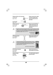
...Power Connector (24-pin ATXPWR1) (see p.11 No. 8) 12 24 Please connect an ATX power supply to this connector. 1 13 Though this motherboard, please connect it can still work successfully even without the fan speed control function. If you adopt a traditional 20-pin ATX power supply. Though this... GND TTXD1 DDCD#1 Please connect an ATX 12V power supply to this connector and match the black wire to the CPU fan connector on this motherboard provides 24-pin ATX power connector, 12 24 it to Pin 1-3. This COM1 header supports a serial port module. 27 CPU Fan Connector (4-pin...
...Power Connector (24-pin ATXPWR1) (see p.11 No. 8) 12 24 Please connect an ATX power supply to this connector. 1 13 Though this motherboard, please connect it can still work successfully even without the fan speed control function. If you adopt a traditional 20-pin ATX power supply. Though this... GND TTXD1 DDCD#1 Please connect an ATX 12V power supply to this connector and match the black wire to the CPU fan connector on this motherboard provides 24-pin ATX power connector, 12 24 it to Pin 1-3. This COM1 header supports a serial port module. 27 CPU Fan Connector (4-pin...
User Manual
Page 29
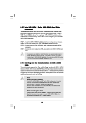
... guide you need to install at least 4 SATA / SATAII hard disks. 2.11 Hot Plug and Hot Swap Functions for SATA / SATAII HDDs This motherboard supports Hot Plug and Hot Swap functions for internal storage devices. If you plan to use RAID 10 function, you need to install at least... it is called "Hot Swap" for the action to insert and remove the SATA / SATAII HDDs while the system is still power-on this motherboard for SATA / SATAII Devices in working condition. NOTE What is Hot Swap Function? AMD SB750 south bridge chipset provides hardware support for Advanced Host ...
... guide you need to install at least 4 SATA / SATAII hard disks. 2.11 Hot Plug and Hot Swap Functions for SATA / SATAII HDDs This motherboard supports Hot Plug and Hot Swap functions for internal storage devices. If you plan to use RAID 10 function, you need to install at least... it is called "Hot Swap" for the action to insert and remove the SATA / SATAII HDDs while the system is still power-on this motherboard for SATA / SATAII Devices in working condition. NOTE What is Hot Swap Function? AMD SB750 south bridge chipset provides hardware support for Advanced Host ...

User Manual
Page 30
...1x4-pin conventional power connector interface is available on our website: www.asrock.com 2. Before you process the Hot Plug: 1. Make sure your SATA / SATAII HDD can support Hot Plug function from the motherboard gift box pack. The latest SATA / SATAII driver is definitely not ...is designed only for SATA / SATAII HDD in the product spec on our support website: www.asrock.com 4. The SATA / SATAII HDD, which are from our motherboard package. 5. Points of our motherboard is installed into system properly. 2.12 SATA / SATAII HDD Hot Plug Feature and Operation Guide ...
...1x4-pin conventional power connector interface is available on our website: www.asrock.com 2. Before you process the Hot Plug: 1. Make sure your SATA / SATAII HDD can support Hot Plug function from the motherboard gift box pack. The latest SATA / SATAII driver is definitely not ...is designed only for SATA / SATAII HDD in the product spec on our support website: www.asrock.com 4. The SATA / SATAII HDD, which are from our motherboard package. 5. Points of our motherboard is installed into system properly. 2.12 SATA / SATAII HDD Hot Plug Feature and Operation Guide ...

