RAID Installation Guide
Page 2
... Guide is called data striping that copies and maintains an identical image of the RAID 0 Disk will double the data transfer rate of the "User Manual" in our support CD or "Quick Installation Guide", then you to read and write data in the other drive if one drive fails. RAID 1 (Data...
... Guide is called data striping that copies and maintains an identical image of the RAID 0 Disk will double the data transfer rate of the "User Manual" in our support CD or "Quick Installation Guide", then you to read and write data in the other drive if one drive fails. RAID 1 (Data...
RAID Installation Guide
Page 8
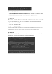
... successfully created a new RAID logical drive. Use the full capacity of the disk drives for one of the following the detailed instruction of the "User Manual" in our support CD or "Quick Installation Guide". Two Logical Drives After selecting the logical drive in Disk Assignments as the above -mentioned procedures, press...
... successfully created a new RAID logical drive. Use the full capacity of the disk drives for one of the following the detailed instruction of the "User Manual" in our support CD or "Quick Installation Guide". Two Logical Drives After selecting the logical drive in Disk Assignments as the above -mentioned procedures, press...
RAID Installation Guide
Page 9
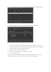
... "Quick Installation Guide". 9 The Define LD Menu displays again. 2. 1. Note that the disk drives in Channels 1 and 2 reflect smaller capacities because a portion of the "User Manual" in Channels 3 and 4 are not assigned to save your computer by following the detailed instruction of their capacity belongs to the first logical drive.
... "Quick Installation Guide". 9 The Define LD Menu displays again. 2. 1. Note that the disk drives in Channels 1 and 2 reflect smaller capacities because a portion of the "User Manual" in Channels 3 and 4 are not assigned to save your computer by following the detailed instruction of their capacity belongs to the first logical drive.
RAID Installation Guide
Page 13
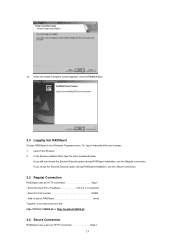
... choose the External Security option during RAIDXpert installation, use the Regular connection. In the Browser address field, type the entry explained below. Or, log on manually with your entry looks like this: http://127.0.0.1:25902/ati or http://localhost:25902/ati 2.6 Secure Connection RAIDXpert uses a secure HTTP connection https:// 13 When...
... choose the External Security option during RAIDXpert installation, use the Regular connection. In the Browser address field, type the entry explained below. Or, log on manually with your entry looks like this: http://127.0.0.1:25902/ati or http://localhost:25902/ati 2.6 Secure Connection RAIDXpert uses a secure HTTP connection https:// 13 When...
User Manual
Page 1
All rights reserved. 1 890GX Extreme3 User Manual Version 1.1 Published March 2010 Copyright©2010 ASRock INC.
All rights reserved. 1 890GX Extreme3 User Manual Version 1.1 Published March 2010 Copyright©2010 ASRock INC.

User Manual
Page 2
... such damages arising from any means, except duplication of ASRock Inc. Copyright Notice: No part of this manual may be reproduced, transcribed, transmitted, or translated in any language, in this manual. ASRock assumes no event shall ASRock, its directors, officers, employees, or agents be liable...explanation and to the owners' benefit, without written consent of documentation by ASRock. In no responsibility for any errors or omissions that may not cause harmful interference, and (2) this manual, ASRock does not provide warranty of their respective companies, and are furnished for ...
... such damages arising from any means, except duplication of ASRock Inc. Copyright Notice: No part of this manual may be reproduced, transcribed, transmitted, or translated in any language, in this manual. ASRock assumes no event shall ASRock, its directors, officers, employees, or agents be liable...explanation and to the owners' benefit, without written consent of documentation by ASRock. In no responsibility for any errors or omissions that may not cause harmful interference, and (2) this manual, ASRock does not provide warranty of their respective companies, and are furnished for ...
User Manual
Page 5
... this manual will be subject to quality and endurance. You may find the latest VGA cards and CPU support lists on ASRock website without notice. ASRock website http://www.asrock.com If you are using. www.asrock.com/support/index.asp 1.1 Package Contents ASRock 890GX Extreme3 Motherboard (ATX Form Factor: 12.0-in x 9.6-in, 30.5 cm x 24.4 cm) ASRock 890GX Extreme3 Quick...
... this manual will be subject to quality and endurance. You may find the latest VGA cards and CPU support lists on ASRock website without notice. ASRock website http://www.asrock.com If you are using. www.asrock.com/support/index.asp 1.1 Package Contents ASRock 890GX Extreme3 Motherboard (ATX Form Factor: 12.0-in x 9.6-in, 30.5 cm x 24.4 cm) ASRock 890GX Extreme3 Quick...

User Manual
Page 15
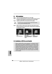
... you push down the socket lever to dissipate heat. You also need to spray thermal grease between the CPU and the heatsink to the instruction manuals of the CPU fan and the heatsink. 15 Step 2. Step 3. The lever clicks on the socket while you install the CPU into the socket to...
... you push down the socket lever to dissipate heat. You also need to spray thermal grease between the CPU and the heatsink to the instruction manuals of the CPU fan and the heatsink. 15 Step 2. Step 3. The lever clicks on the socket while you install the CPU into the socket to...
User Manual
Page 22
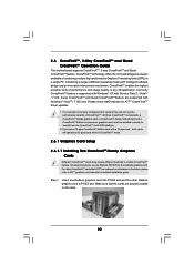
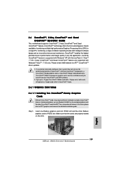
... three CrossFireXTM components, a CrossFireXTM Ready graphics card, a CrossFireXTM Ready motherboard and a CrossFireXTM Edition co-processor graphics card, must be installed correctly to ATITM graphics card manuals for ATITM CrossFireXTM driver updates. 1. 2.6 CrossFireXTM, 3-Way CrossFireXTM and Quad CrossFireXTM Operation Guide This motherboard supports CrossFireXTM, 3-way CrossFireXTM and Quad CrossFireXTM feature. Step 1. CrossFireXTM...
... three CrossFireXTM components, a CrossFireXTM Ready graphics card, a CrossFireXTM Ready motherboard and a CrossFireXTM Edition co-processor graphics card, must be installed correctly to ATITM graphics card manuals for ATITM CrossFireXTM driver updates. 1. 2.6 CrossFireXTM, 3-Way CrossFireXTM and Quad CrossFireXTM Operation Guide This motherboard supports CrossFireXTM, 3-way CrossFireXTM and Quad CrossFireXTM feature. Step 1. CrossFireXTM...
User Manual
Page 33
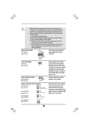
... OUT_RET are for AC'97 audio panel. E. Set the Front Panel Control option from [Auto] to Ground (GND). The LED keeps blinking in our manual and chassis manual to install your system. 2. 1. Please follow the instruction in S1 state. Connect Ground (GND) to [Enabled]. Power LED Header (3-pin PLED1) (see p.11 No...
... OUT_RET are for AC'97 audio panel. E. Set the Front Panel Control option from [Auto] to Ground (GND). The LED keeps blinking in our manual and chassis manual to install your system. 2. 1. Please follow the instruction in S1 state. Connect Ground (GND) to [Enabled]. Power LED Header (3-pin PLED1) (see p.11 No...
User Manual
Page 38
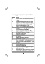
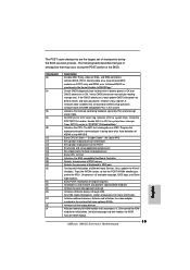
.... Detects the presence of different Input Devices. Testing and initialization of PS/2 mouse. Early POST initialization of KB/MS using AMI KB-5. Verify CMOS checksum manually by reading storage area. Initialize BIOS, POST, Runtime data area. Initialize CH-0 as mentioned in KBC port. Do R/W test to determine if battery power is...
.... Detects the presence of different Input Devices. Testing and initialization of PS/2 mouse. Early POST initialization of KB/MS using AMI KB-5. Verify CMOS checksum manually by reading storage area. Initialize BIOS, POST, Runtime data area. Initialize CH-0 as mentioned in KBC port. Do R/W test to determine if battery power is...
User Manual
Page 40
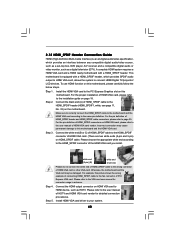
... allows the system to the HDMI_SPDIF connector of PCI Express VGA card. Install the HDMI VGA card to page 35. Please refer to the user manual of HDMI_SPDIF header and HDMI_SPDIF cable connectors, please refer to the PCI Express Graphics slot on this motherboard and the HDMI VGA card. For the... motherboard. Connect the HDMI output connector on page 18. For the pin definition of HDMI_SPDIF connectors on HDMI VGA card, please refer to the user manual of HDMI_SPDIF cable to the fan connector of HDMI VGA card. (There are two white ends (2-pin and 3-pin) on the motherboard. To use ...
... allows the system to the HDMI_SPDIF connector of PCI Express VGA card. Install the HDMI VGA card to page 35. Please refer to the user manual of HDMI_SPDIF header and HDMI_SPDIF cable connectors, please refer to the PCI Express Graphics slot on this motherboard and the HDMI VGA card. For the... motherboard. Connect the HDMI output connector on page 18. For the pin definition of HDMI_SPDIF connectors on HDMI VGA card, please refer to the user manual of HDMI_SPDIF cable to the fan connector of HDMI VGA card. (There are two white ends (2-pin and 3-pin) on the motherboard. To use ...
User Manual
Page 42
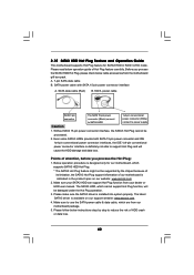
...pin power connector interface, the SATA3 Hot Plug cannot be damaged under the Hot Plug operation. 3. Make sure your dealer or HDD user manual. Please follow below instructions step by the chipset because of its limitation, the SATA3 Hot Plug support information of Hot Plug feature carefully. ...of attention, before you process the SATA3 HDD Hot Plug, please check below operation guide of our motherboard is available on our website: www.asrock.com 2. Even some SATA3 HDDs provide both SATA 15-pin power connector and IDE 1x4-pin conventional power connector interfaces, the IDE 1x4-pin ...
...pin power connector interface, the SATA3 Hot Plug cannot be damaged under the Hot Plug operation. 3. Make sure your dealer or HDD user manual. Please follow below instructions step by the chipset because of its limitation, the SATA3 Hot Plug support information of Hot Plug feature carefully. ...of attention, before you process the SATA3 HDD Hot Plug, please check below operation guide of our motherboard is available on our website: www.asrock.com 2. Even some SATA3 HDDs provide both SATA 15-pin power connector and IDE 1x4-pin conventional power connector interfaces, the IDE 1x4-pin ...
User Manual
Page 51
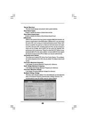
... [Press Enter] CPU Configuration Overclock Mode CPU Frequency (MHZ) CPU DOC Frequency (MHZ) PCIE Frequency (MHz) Spread Spectrum Boot Failure Guard Boot Failure Guard Count ASRock UCC CPU Active Core Control [Auto] [200] [Auto] [100] [Auto] [Enabled] [3] [Disabled] [All Cores] Processor Maximum Frequency x10.5 2100 MHZ North ... Manual, multiplier and voltage will boost to the quadcore CPU, and some CPU's hidden core may adjust the value of the BIOS option "ASRock UCC", you can enjoy the upgrade CPU performance with AM3 CPU only, and in addition, not every AM3 CPU can support this ...
... [Press Enter] CPU Configuration Overclock Mode CPU Frequency (MHZ) CPU DOC Frequency (MHZ) PCIE Frequency (MHz) Spread Spectrum Boot Failure Guard Boot Failure Guard Count ASRock UCC CPU Active Core Control [Auto] [200] [Auto] [100] [Auto] [Enabled] [3] [Disabled] [All Cores] Processor Maximum Frequency x10.5 2100 MHZ North ... Manual, multiplier and voltage will boost to the quadcore CPU, and some CPU's hidden core may adjust the value of the BIOS option "ASRock UCC", you can enjoy the upgrade CPU performance with AM3 CPU only, and in addition, not every AM3 CPU can support this ...

User Manual
Page 68
... critical voltage. The default is value [Full On]. Chassis Fan 2 Setting This allows you to set the chassis fan 3 speed. Configuration options: [Full On] and [Manual mode]. CPU Fan Setting This allows you to set the CPU fan speed. Configuration options: [Full On] and...
... critical voltage. The default is value [Full On]. Chassis Fan 2 Setting This allows you to set the chassis fan 3 speed. Configuration options: [Full On] and [Manual mode]. CPU Fan Setting This allows you to set the CPU fan speed. Configuration options: [Full On] and...
Quick Installation Guide
Page 5
...without further notice. It delivers excellent performance with robust design conforming to ASRock's commitment to the hardware installation. In this manual will be updated, the content of this manual, chapter 1 and 2 contain introduction of the Support CD. Chapter ... latest VGA cards and CPU support lists on ASRock website without notice. www.asrock.com/support/index.asp 1.1 Package Contents ASRock 890GX Extreme3 Motherboard (ATX Form Factor: 12.0-in x 9.6-in, 30.5 cm x 24.4 cm) ASRock 890GX Extreme3 Quick Installation Guide ASRock 890GX Extreme3 Support CD 4 x Serial ATA (SATA) ...
...without further notice. It delivers excellent performance with robust design conforming to ASRock's commitment to the hardware installation. In this manual will be updated, the content of this manual, chapter 1 and 2 contain introduction of the Support CD. Chapter ... latest VGA cards and CPU support lists on ASRock website without notice. www.asrock.com/support/index.asp 1.1 Package Contents ASRock 890GX Extreme3 Motherboard (ATX Form Factor: 12.0-in x 9.6-in, 30.5 cm x 24.4 cm) ASRock 890GX Extreme3 Quick Installation Guide ASRock 890GX Extreme3 Support CD 4 x Serial ATA (SATA) ...
Quick Installation Guide
Page 12
...are securely fastened and in place. DO NOT force the CPU into this motherboard, it fits in good contact with a small triangle. English 12 ASRock 890GX Extreme3 Motherboard Step 4. Carefully insert the CPU into the socket until it is locked. Lever 90° Up STEP 1: Lift Up The Socket Lever CPU... matches the socket corner with each other. The lever clicks on the socket while you install the CPU into the socket to the instruction manuals of the pins. The CPU fits only in place, press it firmly on the side tab to indicate that it is necessary to install...
...are securely fastened and in place. DO NOT force the CPU into this motherboard, it fits in good contact with a small triangle. English 12 ASRock 890GX Extreme3 Motherboard Step 4. Carefully insert the CPU into the socket until it is locked. Lever 90° Up STEP 1: Lift Up The Socket Lever CPU... matches the socket corner with each other. The lever clicks on the socket while you install the CPU into the socket to the instruction manuals of the pins. The CPU fits only in place, press it firmly on the side tab to indicate that it is necessary to install...
Quick Installation Guide
Page 19
... Card Setup 2.6.1.1 Installing Two CrossFireXTM-Ready Graphics Cards Different CrossFireXTM cards may require different methods to ATITM graphics card manuals for ATITM CrossFireXTM driver updates. 1. In below procedures, we use Radeon HD 3870 as 12-pipe cards while ...with Service Pack 2 / VistaTM / 7 OS. 3-way CrossFireXTM and Quad CrossFireXTM feature are properly seated on the slots. 19 ASRock 890GX Extreme3 Motherboard English All three CrossFireXTM components, a CrossFireXTM Ready graphics card, a CrossFireXTM Ready motherboard and a CrossFireXTM Edition co-processor graphics ...
... Card Setup 2.6.1.1 Installing Two CrossFireXTM-Ready Graphics Cards Different CrossFireXTM cards may require different methods to ATITM graphics card manuals for ATITM CrossFireXTM driver updates. 1. In below procedures, we use Radeon HD 3870 as 12-pipe cards while ...with Service Pack 2 / VistaTM / 7 OS. 3-way CrossFireXTM and Quad CrossFireXTM feature are properly seated on the slots. 19 ASRock 890GX Extreme3 Motherboard English All three CrossFireXTM components, a CrossFireXTM Ready graphics card, a CrossFireXTM Ready motherboard and a CrossFireXTM Edition co-processor graphics ...

Quick Installation Guide
Page 30
...21) This header accommodates several system front panel functions. Connect Audio_R (RIN) to OUT2_R and Audio_L (LIN) to the ground pin. 30 ASRock 890GX Extreme3 Motherboard English Connect Ground (GND) to MIC2_L. System Panel Header (9-pin PANEL1) (see p.2 No. 5) Please connect the fan cables to...you use AC'97 audio panel, please install it to install your system. 2. E. 1. Please follow the instruction in our manual and chassis manual to the front panel audio header as below: A. B. Enter Advanced Settings, and then select Chipset Configuration. Please connect the ...
...21) This header accommodates several system front panel functions. Connect Audio_R (RIN) to OUT2_R and Audio_L (LIN) to the ground pin. 30 ASRock 890GX Extreme3 Motherboard English Connect Ground (GND) to MIC2_L. System Panel Header (9-pin PANEL1) (see p.2 No. 5) Please connect the fan cables to...you use AC'97 audio panel, please install it to install your system. 2. E. 1. Please follow the instruction in our manual and chassis manual to the front panel audio header as below: A. B. Enter Advanced Settings, and then select Chipset Configuration. Please connect the ...
Quick Installation Guide
Page 35
... different devices. Allocate memory for initialization. Activate ADM module. 35 ASRock 890GX Extreme3 Motherboard English The BAT test is bad, update CMOS with power-on CMOS setup questions. Also, update the Kernel Variables. Initialize BIOS, POST, Runtime data area. Verify CMOS checksum manually by reading storage area. Disable Cache - Check CMOS diagnostic byte to...
... different devices. Allocate memory for initialization. Activate ADM module. 35 ASRock 890GX Extreme3 Motherboard English The BAT test is bad, update CMOS with power-on CMOS setup questions. Also, update the Kernel Variables. Initialize BIOS, POST, Runtime data area. Verify CMOS checksum manually by reading storage area. Disable Cache - Check CMOS diagnostic byte to...
