
User Manual
Page 3
... and Quad CrossFireXTM Operation Guide 22 2.7 ATITM Hybrid CrossFireXTM Operation Guide 28 2.8 Jumpers Setup 30 2.9 Onboard Headers and Connectors 31 2.10 Smart Switches 36 2.11 Dr. Debug 37 2.12 HDMI_SPDIF Header Connection Guide 40 2.13 Serial ATA3 (SATA3) Hard Disks Installation 41 2.14 Hot Plug and Hot Swap Functions for SATA3 HDDs...
... and Quad CrossFireXTM Operation Guide 22 2.7 ATITM Hybrid CrossFireXTM Operation Guide 28 2.8 Jumpers Setup 30 2.9 Onboard Headers and Connectors 31 2.10 Smart Switches 36 2.11 Dr. Debug 37 2.12 HDMI_SPDIF Header Connection Guide 40 2.13 Serial ATA3 (SATA3) Hard Disks Installation 41 2.14 Hot Plug and Hot Swap Functions for SATA3 HDDs...
User Manual
Page 8
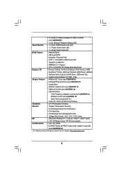
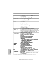
...: +12V, +5V, +3.3V, Vcore OS - CPU, VCCM, NB, SB Voltage Multi-adjustment Support CD - OEM and Trial; ASRock OC Tuner (see CAUTION 13) - ASRock OC DNA (see CAUTION 10) - Turbo 25 / Turbo 30 GPU Overclocking Hardware - CPU/Chassis Fan Multi-Speed Control - Supports "Plug...Version), AMD OverDriveTM Utility, AMD Live! FCC, CE, WHQL - ErP/EuP Ready (ErP/EuP ready power supply is required) (see CAUTION 8) - 1 x Dr. Debug (7-Segment Debug LED) Smart Switch - 1 x Clear CMOS Switch with LED - 1 x Power Switch with LED - 1 x Reset Switch with LED BIOS Feature - 8Mb...
...: +12V, +5V, +3.3V, Vcore OS - CPU, VCCM, NB, SB Voltage Multi-adjustment Support CD - OEM and Trial; ASRock OC Tuner (see CAUTION 13) - ASRock OC DNA (see CAUTION 10) - Turbo 25 / Turbo 30 GPU Overclocking Hardware - CPU/Chassis Fan Multi-Speed Control - Supports "Plug...Version), AMD OverDriveTM Utility, AMD Live! FCC, CE, WHQL - ErP/EuP Ready (ErP/EuP ready power supply is required) (see CAUTION 8) - 1 x Dr. Debug (7-Segment Debug LED) Smart Switch - 1 x Clear CMOS Switch with LED - 1 x Power Switch with LED - 1 x Reset Switch with LED BIOS Feature - 8Mb...
User Manual
Page 11
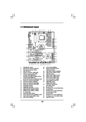
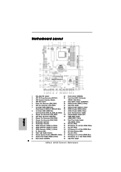
...MIC IN NEC MPD720200 PCIE2 Sideport memory 128MB PCI Express 2.0 Super I/O RoHS PCI1 Six-Core CPU Ready 8Mb BIOS NEC USB 3.0 PCIE3 890GX Extreme3 PCI2 CMOS BATTERY ErP/EuP Ready AMD SB850 Chipset AUDIO CODEC PCIE4 Designed in Taipei PCI3 HD_AUDIO1 COM1 IR1 1 1 1 1 HDMI_SPDIF1 USB6_7 ... 1 1394a USB_PW3 1 USB10_11 CLRCMOS1 1 USB12_13 FRONT_1394 1 1 1 PWRBTN RSTBTN PLED1 1 PANEL 1 PLED PWRBTN 1 HDLED RESET SATA3 6Gb/s SATA3_1_2 SATA3_3_4 SATA3_5_6 Dr. Debug SPEAKER1 1 34 33 32 31 30 29 28 27 26 25 24 23 22 21 FSB2.6GHz 140W CPU 30.5cm (12.0-in) 9 10 11...
...MIC IN NEC MPD720200 PCIE2 Sideport memory 128MB PCI Express 2.0 Super I/O RoHS PCI1 Six-Core CPU Ready 8Mb BIOS NEC USB 3.0 PCIE3 890GX Extreme3 PCI2 CMOS BATTERY ErP/EuP Ready AMD SB850 Chipset AUDIO CODEC PCIE4 Designed in Taipei PCI3 HD_AUDIO1 COM1 IR1 1 1 1 1 HDMI_SPDIF1 USB6_7 ... 1 1394a USB_PW3 1 USB10_11 CLRCMOS1 1 USB12_13 FRONT_1394 1 1 1 PWRBTN RSTBTN PLED1 1 PANEL 1 PLED PWRBTN 1 HDLED RESET SATA3 6Gb/s SATA3_1_2 SATA3_3_4 SATA3_5_6 Dr. Debug SPEAKER1 1 34 33 32 31 30 29 28 27 26 25 24 23 22 21 FSB2.6GHz 140W CPU 30.5cm (12.0-in) 9 10 11...
User Manual
Page 37
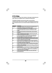
...Checkpoint Before D1 D1 D0 D2 D3 D4 D5 D6 D7 D8 D9 DA Description Early chipset initialization is given to it . 2.11 Dr. Debug Dr. Debug is necessary, control flows to checkpoint E0. Early super I/O initialization is enabled. Go to execute serial flash. Do additional chipset initialization. ... and cache first 8MB. Determine whether to flat mode with 4GB limit and GA20 enabled. Store the Uncompressed pointer for reading the Dr. Debug codes. Copying Main BIOS into memory. Leaves all RAM below for future use in scratch CMOS. The Bootblock initialization code sets up...
...Checkpoint Before D1 D1 D0 D2 D3 D4 D5 D6 D7 D8 D9 DA Description Early chipset initialization is given to it . 2.11 Dr. Debug Dr. Debug is necessary, control flows to checkpoint E0. Early super I/O initialization is enabled. Go to execute serial flash. Do additional chipset initialization. ... and cache first 8MB. Determine whether to flat mode with 4GB limit and GA20 enabled. Store the Uncompressed pointer for reading the Dr. Debug codes. Copying Main BIOS into memory. Leaves all RAM below for future use in scratch CMOS. The Bootblock initialization code sets up...
Quick Installation Guide
Page 2
... PCI Express 2.0 x1 Slot (PCIE1; Blue) 18 Dr. Debug (LED) 39 SPI Flash Memory (8Mb) 19 Power LED Header (PLED1) 40 PCI Slot (PCI1) 20 Chassis Speaker Header (SPEAKER 1, White) 41 PCI Express 2.0 x16 Slot (PCIE2; White) 22 Reset Switch (RSTBTN) 43 USB_PW2 Jumper 2 ASRock 890GX Extreme3 Motherboard Motherboard Layout English 1 PS2_USB_PW1 Jumper 23 Power...
... PCI Express 2.0 x1 Slot (PCIE1; Blue) 18 Dr. Debug (LED) 39 SPI Flash Memory (8Mb) 19 Power LED Header (PLED1) 40 PCI Slot (PCI1) 20 Chassis Speaker Header (SPEAKER 1, White) 41 PCI Express 2.0 x16 Slot (PCIE2; White) 22 Reset Switch (RSTBTN) 43 USB_PW2 Jumper 2 ASRock 890GX Extreme3 Motherboard Motherboard Layout English 1 PS2_USB_PW1 Jumper 23 Power...
Quick Installation Guide
Page 8
...Fan Multi-Speed Control - SMBIOS 2.3.1 Support - Explorer, AMD Fusion, ASRock Software Suite (CyberLink DVD Suite - ACPI 1.1 Compliance Wake Up Events - ASRock U-COP (see CAUTION 12) - Microsoft® Windows® 7 /...ASRock OC Tuner (see CAUTION 8) - 1 x Dr. Debug (7-Segment Debug LED) Smart Switch - 1 x Clear CMOS Switch with LED - 1 x Power Switch with LED - 1 x Reset Switch with LED BIOS Feature - 8Mb AMI BIOS - ASRock Instant Flash (see CAUTION 15) * For detailed product information, please visit our website: http://www.asrock.com English 8 ASRock 890GX Extreme3...
...Fan Multi-Speed Control - SMBIOS 2.3.1 Support - Explorer, AMD Fusion, ASRock Software Suite (CyberLink DVD Suite - ACPI 1.1 Compliance Wake Up Events - ASRock U-COP (see CAUTION 12) - Microsoft® Windows® 7 /...ASRock OC Tuner (see CAUTION 8) - 1 x Dr. Debug (7-Segment Debug LED) Smart Switch - 1 x Clear CMOS Switch with LED - 1 x Power Switch with LED - 1 x Reset Switch with LED BIOS Feature - 8Mb AMI BIOS - ASRock Instant Flash (see CAUTION 15) * For detailed product information, please visit our website: http://www.asrock.com English 8 ASRock 890GX Extreme3...

Quick Installation Guide
Page 34
...ASRock 890GX Extreme3 Motherboard Verify the bootblock checksum. Test base 512KB memory. Set stack. Both key sequence and OEM specific method is checked to determine if BIOS recovery is given to it . Determine whether to flat mode with 4GB limit and GA20 enabled. Store the Uncompressed pointer for reading the Dr. Debug... memory. Please see the diagrams below 1MB Read-Write including E000 and F000 shadow areas but closing SMRAM. 2.11 Dr. Debug Dr. Debug is given to it . The following table describes the type of RAM. Main BIOS checksum is done. Perform keyboard...
...ASRock 890GX Extreme3 Motherboard Verify the bootblock checksum. Test base 512KB memory. Set stack. Both key sequence and OEM specific method is checked to determine if BIOS recovery is given to it . Determine whether to flat mode with 4GB limit and GA20 enabled. Store the Uncompressed pointer for reading the Dr. Debug... memory. Please see the diagrams below 1MB Read-Write including E000 and F000 shadow areas but closing SMRAM. 2.11 Dr. Debug Dr. Debug is given to it . The following table describes the type of RAM. Main BIOS checksum is done. Perform keyboard...
