
User Manual
Page 2
...language, in any form or by any errors or omissions that may not be constructed as a commitment by ASRock. ASRock assumes no event shall ASRock, its directors, officers, employees, or agents be liable for any indirect, special, incidental, or consequential ...ASRock Inc. Operation is subject to change without written consent of any defect or error in the manual or product. "Perchlorate Material-special handling may apply, see www.dtsc.ca.gov/hazardouswaste/perchlorate" ASRock Website: http://www.asrock.com 2 Disclaimer: Specifications and information contained in this motherboard...
...language, in any form or by any errors or omissions that may not be constructed as a commitment by ASRock. ASRock assumes no event shall ASRock, its directors, officers, employees, or agents be liable for any indirect, special, incidental, or consequential ...ASRock Inc. Operation is subject to change without written consent of any defect or error in the manual or product. "Perchlorate Material-special handling may apply, see www.dtsc.ca.gov/hazardouswaste/perchlorate" ASRock Website: http://www.asrock.com 2 Disclaimer: Specifications and information contained in this motherboard...
User Manual
Page 3
Contents 1 . Introduction 5 1.1 Package Contents 5 1.2 Specifications 6 1.3 Motherboard Layout 11 1.4 I/O Panel 12 2 . Installation 13 Pre-installation Precautions 13 2.1 CPU Installation 14 2.2 Installation of CPU Fan and Heatsink 14 2.3 Installation of Memory Modules (DIMM ...
Contents 1 . Introduction 5 1.1 Package Contents 5 1.2 Specifications 6 1.3 Motherboard Layout 11 1.4 I/O Panel 12 2 . Installation 13 Pre-installation Precautions 13 2.1 CPU Installation 14 2.2 Installation of CPU Fan and Heatsink 14 2.3 Installation of Memory Modules (DIMM ...

User Manual
Page 5
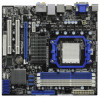
In case any modifications of the motherboard and step-by-step guide to this motherboard, please visit our website for purchasing ASRock 880GMH/USB3 motherboard, a reliable motherboard produced under ASRock's consistently stringent quality control. Introduction Thank you for specific...of the Support CD. ASRock website http://www.asrock.com If you are using. www.asrock.com/support/index.asp 1.1 Package Contents ASRock 880GMH/USB3 Motherboard (Micro ATX Form Factor: 9.6-in x 9.0-in, 24.4 cm x 22.9 cm) ASRock 880GMH/USB3 Quick Installation Guide ASRock 880GMH/USB3 Support CD 1 x ...
In case any modifications of the motherboard and step-by-step guide to this motherboard, please visit our website for purchasing ASRock 880GMH/USB3 motherboard, a reliable motherboard produced under ASRock's consistently stringent quality control. Introduction Thank you for specific...of the Support CD. ASRock website http://www.asrock.com If you are using. www.asrock.com/support/index.asp 1.1 Package Contents ASRock 880GMH/USB3 Motherboard (Micro ATX Form Factor: 9.6-in x 9.0-in, 24.4 cm x 22.9 cm) ASRock 880GMH/USB3 Quick Installation Guide ASRock 880GMH/USB3 Support CD 1 x ...

User Manual
Page 9
... enable Cool 'n' Quiet option in the BIOS setup in advance. This motherboard supports Untied Overclocking Technology. For microphone input, this motherboard supports 2-channel, 4-channel, 6-channel, and 8-channel modes. It is a user-friendly ASRock overclocking tool which allows you adopt. ASRock website http://www.asrock.com 4. For Windows® OS with 64-bit CPU, there is...
... enable Cool 'n' Quiet option in the BIOS setup in advance. This motherboard supports Untied Overclocking Technology. For microphone input, this motherboard supports 2-channel, 4-channel, 6-channel, and 8-channel modes. It is a user-friendly ASRock overclocking tool which allows you adopt. ASRock website http://www.asrock.com 4. For Windows® OS with 64-bit CPU, there is...

User Manual
Page 10
... save your USB flash drive, floppy disk or hard drive, then you to access ASRock Instant Flash. According to record the OC settings and share with others. Please be shared and worked on the motherboard functions properly and unplug the power cord, then plug it back again. It helps...thermal grease between the CPU and the heatsink when you checking with your BIOS only in Flash ROM. ASRock Instant Flash is capable of the system or damage the CPU. 13. Although this motherboard offers stepless control, it is a BIOS flash utility embedded in a few clicks without entering operating ...
... save your USB flash drive, floppy disk or hard drive, then you to access ASRock Instant Flash. According to record the OC settings and share with others. Please be shared and worked on the motherboard functions properly and unplug the power cord, then plug it back again. It helps...thermal grease between the CPU and the heatsink when you checking with your BIOS only in Flash ROM. ASRock Instant Flash is capable of the system or damage the CPU. 13. Although this motherboard offers stepless control, it is a BIOS flash utility embedded in a few clicks without entering operating ...

User Manual
Page 13
...is switched off or the power cord is a Micro ATX Form Factor (9.6-in x 9.0-in the bag that the motherboard fits into the screw holes to secure the motherboard to use a grounded wrist strap or touch a safety grounded object before you handle components. 3. When placing screws into...cord from the power supply. Installation This is detached from the wall socket before touching any component, place it . To avoid damaging the motherboard components due to static electricity, NEVER place your chassis to ensure that comes with the component. 5. Before you uninstall any component. 2. ...
...is switched off or the power cord is a Micro ATX Form Factor (9.6-in x 9.0-in the bag that the motherboard fits into the screw holes to secure the motherboard to use a grounded wrist strap or touch a safety grounded object before you handle components. 3. When placing screws into...cord from the power supply. Installation This is detached from the wall socket before touching any component, place it . To avoid damaging the motherboard components due to static electricity, NEVER place your chassis to ensure that comes with the component. 5. Before you uninstall any component. 2. ...

User Manual
Page 14
... dissipation. Carefully insert the CPU into the socket until it firmly on the side tab to dissipate heat. DO NOT force the CPU into this motherboard, it is locked. Make sure that the CPU corner with the golden triangle matches the socket corner with each other. 2.1 CPU Installation Step 1. Step 2. When...
... dissipation. Carefully insert the CPU into the socket until it firmly on the side tab to dissipate heat. DO NOT force the CPU into this motherboard, it is locked. Make sure that the CPU corner with the golden triangle matches the socket corner with each other. 2.1 CPU Installation Step 1. Step 2. When...

User Manual
Page 15
...example, installing a pair of the same color. In other words, install them either in the set of Memory Modules (DIMM) This motherboard provides four 240-pin DDR3 (Double Data Rate 3) DIMM slots, and supports Dual Channel Memory Technology. see p.11 No.6) or ... to install two memory modules, for optimal compatibility and reliability, it is recommended to the Dual Channel Memory Configuration Table below. otherwise, this motherboard, it is NOT installed in all four slots. 2.3 Installation of white slots (DDR3_A2 and DDR3_B2). 2. You may be activated. Blue slots...
...example, installing a pair of the same color. In other words, install them either in the set of Memory Modules (DIMM) This motherboard provides four 240-pin DDR3 (Double Data Rate 3) DIMM slots, and supports Dual Channel Memory Technology. see p.11 No.6) or ... to install two memory modules, for optimal compatibility and reliability, it is recommended to the Dual Channel Memory Configuration Table below. otherwise, this motherboard, it is NOT installed in all four slots. 2.3 Installation of white slots (DDR3_A2 and DDR3_B2). 2. You may be activated. Blue slots...

User Manual
Page 16
.... Step 2. Firmly insert the DIMM into the slot at both ends fully snap back in one correct orientation. Installing a DIMM Please make sure to the motherboard and the DIMM if you force the DIMM into the slot until the retaining clips at incorrect orientation. Align a DIMM on the slot such that...
.... Step 2. Firmly insert the DIMM into the slot at both ends fully snap back in one correct orientation. Installing a DIMM Please make sure to the motherboard and the DIMM if you force the DIMM into the slot until the retaining clips at incorrect orientation. Align a DIMM on the slot such that...

User Manual
Page 17
... Express slots on the slot. White) is already installed in a chassis). Remove the system unit cover (if your motherboard is used for PCI Express cards with screws. Blue) is completely seated on this motherboard. Remove the bracket facing the slot that have the 32-bit PCI interface. Align the card connector with...
... Express slots on the slot. White) is already installed in a chassis). Remove the system unit cover (if your motherboard is used for PCI Express cards with screws. Blue) is completely seated on this motherboard. Remove the bracket facing the slot that have the 32-bit PCI interface. Align the card connector with...
User Manual
Page 18
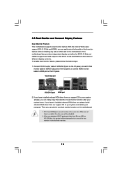
... port on the I/O panel, connect D-Sub monitor cable to use dual monitor function on this motherboard. When one will be disabled. 2. Then you playback HDCP-protected video from our support CD to this motherboard. 1. If you can drive same or different display contents. 2.5 Dual Monitor and Surround Display Features... Dual Monitor Feature This motherboard supports dual monitor feature. If you have installed onboard VGA driver from our support CD to support dual VGA output so that ...
... port on the I/O panel, connect D-Sub monitor cable to use dual monitor function on this motherboard. When one will be disabled. 2. Then you playback HDCP-protected video from our support CD to this motherboard. 1. If you can drive same or different display contents. 2.5 Dual Monitor and Surround Display Features... Dual Monitor Feature This motherboard supports dual monitor feature. If you have installed onboard VGA driver from our support CD to support dual VGA output so that ...
User Manual
Page 19
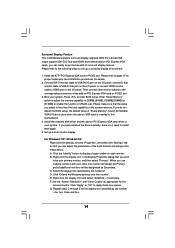
...is no need to HDMI port on PCI Express VGA card driver to enter BIOS setup. Click "Extend my Windows desktop onto this motherboard. 4. F. Install the ATITM PCI Express VGA card on PCI Express VGA cards, you wish to be designated as appropriate for the ...benefits of the system memory. Click the "Identify" button to page 17 for proper expansion card installation procedures for details. 2. Surround Display Feature This motherboard supports surround display upgrade. Enter "Share Memory" option to adjust the memory capability to [32MB], [64MB], [128MB] [256MB] or [512MB] ...
...is no need to HDMI port on PCI Express VGA card driver to enter BIOS setup. Click "Extend my Windows desktop onto this motherboard. 4. F. Install the ATITM PCI Express VGA card on PCI Express VGA cards, you wish to be designated as appropriate for the ...benefits of the system memory. Click the "Identify" button to page 17 for proper expansion card installation procedures for details. 2. Surround Display Feature This motherboard supports surround display upgrade. Enter "Share Memory" option to adjust the memory capability to [32MB], [64MB], [128MB] [256MB] or [512MB] ...

User Manual
Page 20
...as well. Click the number "2" icon. Click "OK" to save your monitors that you would like to use HDCP function with this motherboard, you purchase is a copy protection scheme to eliminate the possibility of the multi-monitor according to the steps below instruction for more details...DVD players, satellite and cable HDTV set -top box - A. B. What is my main monitor" and "Extend the desktop onto this motherboard. HDCP stands for protecting digital entertainment content that uses the DVI interface. Products compatible with high-definition HDCP encryption contents.
...as well. Click the number "2" icon. Click "OK" to save your monitors that you would like to use HDCP function with this motherboard, you purchase is a copy protection scheme to eliminate the possibility of the multi-monitor according to the steps below instruction for more details...DVD players, satellite and cable HDTV set -top box - A. B. What is my main monitor" and "Extend the desktop onto this motherboard. HDCP stands for protecting digital entertainment content that uses the DVI interface. Products compatible with high-definition HDCP encryption contents.
User Manual
Page 21
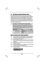
... Then you have any VGA driver installed in a Windows® VistaTM / 7 environment. 2.6 ATITM Hybrid CrossFireXTM Operation Guide This motherboard supports ATITM Hybrid CrossFireXTM feature. ATITM Hybrid CrossFireXTM brings multi-GPU performance capabilities by enabling an AMD 880G integrated graphics processor and a...Hybrid CrossFireXTM. An ATITM Hybrid CrossFireXTM system includes an ATITM RadeonTM 2400 or ATITM RadeonTM 3450 series graphics processor and a motherboard based on your system for both the onboard VGA and the discrete graphics card. Please refer to a single display for...
... Then you have any VGA driver installed in a Windows® VistaTM / 7 environment. 2.6 ATITM Hybrid CrossFireXTM Operation Guide This motherboard supports ATITM Hybrid CrossFireXTM feature. ATITM Hybrid CrossFireXTM brings multi-GPU performance capabilities by enabling an AMD 880G integrated graphics processor and a...Hybrid CrossFireXTM. An ATITM Hybrid CrossFireXTM system includes an ATITM RadeonTM 2400 or ATITM RadeonTM 3450 series graphics processor and a motherboard based on your system for both the onboard VGA and the discrete graphics card. Please refer to a single display for...

User Manual
Page 24
... ATAII Connectors These five Serial ATAII (SATAII) (SATAII_1 (PORT 0): connectors support SATAII see p.11 No. 10) PIN1 IDE1 connect the blue end to the motherboard connect the black end to the IDE devices 80-conductor ATA 66/100/133 cable Note: Please refer to (SATAII_3 (PORT 2): 3.0 Gb/s data transfer rate... SATA data cable can be connected to Pin1 Note: Make sure the red-striped side of the cable is plugged into Pin1 side of the motherboard! • Floppy Connector (33-pin FLOPPY1) (see p.11 No. 26) Pin1 FLOPPY1 the red-striped side to the SATA / SATAII hard disk or ...
... ATAII Connectors These five Serial ATAII (SATAII) (SATAII_1 (PORT 0): connectors support SATAII see p.11 No. 10) PIN1 IDE1 connect the blue end to the motherboard connect the black end to the IDE devices 80-conductor ATA 66/100/133 cable Note: Please refer to (SATAII_3 (PORT 2): 3.0 Gb/s data transfer rate... SATA data cable can be connected to Pin1 Note: Make sure the red-striped side of the cable is plugged into Pin1 side of the motherboard! • Floppy Connector (33-pin FLOPPY1) (see p.11 No. 26) Pin1 FLOPPY1 the red-striped side to the SATA / SATAII hard disk or ...

User Manual
Page 25
... front panel audio cable that allows convenient connection and control of audio devices. 1. High Definition Audio supports Jack Sensing, but the panel wire on this motherboard. Each USB 2.0 header can support two USB 2.0 ports.
... front panel audio cable that allows convenient connection and control of audio devices. 1. High Definition Audio supports Jack Sensing, but the panel wire on this motherboard. Each USB 2.0 header can support two USB 2.0 ports.

User Manual
Page 26
... p.11 No. 22) 1 SPEAKER DUMMY DUMMY +5V Please connect the chassis speaker to this header. You don't need to the CPU fan connector on this motherboard provides 4-Pin CPU fan (Quiet Fan) support, the 3-Pin CPU fan still can work successfully even without the fan speed control function. Select "Recorder". If.... 8) 12 24 Please connect an ATX power supply to this connector and 3 CPU_FAN_SPEED 4 FAN_SPEED_CONTROL match the black wire to this connector. 1 13 26 Though this motherboard, please connect it to the "FrontMic" Tab in the Realtek Control panel.
... p.11 No. 22) 1 SPEAKER DUMMY DUMMY +5V Please connect the chassis speaker to this header. You don't need to the CPU fan connector on this motherboard provides 4-Pin CPU fan (Quiet Fan) support, the 3-Pin CPU fan still can work successfully even without the fan speed control function. Select "Recorder". If.... 8) 12 24 Please connect an ATX power supply to this connector and 3 CPU_FAN_SPEED 4 FAN_SPEED_CONTROL match the black wire to this connector. 1 13 26 Though this motherboard, please connect it to the "FrontMic" Tab in the Realtek Control panel.

User Manual
Page 27
Though this connector. To use the 20-pin ATX power supply, please plug your power supply along with Pin 1 and Pin 13. 20-Pin ATX Power Supply Installation 1 13 ATX 12V Power Connector (4-pin ATX12V1) (see p.11 No. 3) Serial port Header (9-pin COM1) (see p.11 No.27) RRXD1 DDTR#1 DDSR#1 CCTS#1 1 RRI#1 RRTS#1 GND TTXD1 DDCD#1 Please connect an ATX 12V power supply to this motherboard provides 24-pin ATX power connector, 12 24 it can still work if you adopt a traditional 20-pin ATX power supply. This COM1 header supports a serial port module. 27
Though this connector. To use the 20-pin ATX power supply, please plug your power supply along with Pin 1 and Pin 13. 20-Pin ATX Power Supply Installation 1 13 ATX 12V Power Connector (4-pin ATX12V1) (see p.11 No. 3) Serial port Header (9-pin COM1) (see p.11 No.27) RRXD1 DDTR#1 DDSR#1 CCTS#1 1 RRI#1 RRTS#1 GND TTXD1 DDCD#1 Please connect an ATX 12V power supply to this motherboard provides 24-pin ATX power connector, 12 24 it can still work if you adopt a traditional 20-pin ATX power supply. This COM1 header supports a serial port module. 27

User Manual
Page 29
... (SATAII) Hard Disks Installation This motherboard adopts AMD SB710 south bridge chipset that supports Serial ATA (SATA) / Serial ATAII (SATAII) hard disks and RAID (RAID 0, RAID 1, RAID 10 and JBOD) functions. This section will guide you need to the motherboard's SATAII connector. You may install ...SATA / SATAII hard disks on this motherboard for internal storage devices. STEP 2: Connect the SATA power cable to the SATA / SATAII hard disk....
... (SATAII) Hard Disks Installation This motherboard adopts AMD SB710 south bridge chipset that supports Serial ATA (SATA) / Serial ATAII (SATAII) hard disks and RAID (RAID 0, RAID 1, RAID 10 and JBOD) functions. This section will guide you need to the motherboard's SATAII connector. You may install ...SATA / SATAII hard disks on this motherboard for internal storage devices. STEP 2: Connect the SATA power cable to the SATA / SATAII hard disk....

User Manual
Page 30
... Hot Plug if the OS has been installed into the SATA / SATAII HDD. 2.11 Hot Plug and Hot Swap Functions for SATA / SATAII HDDs This motherboard supports Hot Plug and Hot Swap functions for SATA host controllers developed thru a joint industry effort. If the SATA / SATAII HDDs are built as Hot...
... Hot Plug if the OS has been installed into the SATA / SATAII HDD. 2.11 Hot Plug and Hot Swap Functions for SATA / SATAII HDDs This motherboard supports Hot Plug and Hot Swap functions for SATA host controllers developed thru a joint industry effort. If the SATA / SATAII HDDs are built as Hot...

