User Manual
Page 1
880GM-LE User Manual Version 1.0 Published April 2010 Copyright©2010 ASRock INC. All rights reserved. 1
880GM-LE User Manual Version 1.0 Published April 2010 Copyright©2010 ASRock INC. All rights reserved. 1
User Manual
Page 2
... damages arising from any defect or error in this manual are used only for informational use only and subject to the owners' benefit, without written consent of ASRock Inc. With respect to the contents of this manual, ASRock does not provide warranty of any interference received, including... interference that may appear in this manual may or may not be registered trademarks or copyrights of their...
... damages arising from any defect or error in this manual are used only for informational use only and subject to the owners' benefit, without written consent of ASRock Inc. With respect to the contents of this manual, ASRock does not provide warranty of any interference received, including... interference that may appear in this manual may or may not be registered trademarks or copyrights of their...
User Manual
Page 5
... about the model you for purchasing ASRock 880GM-LE motherboard, a reliable motherboard produced under ASRock's consistently stringent quality control. ASRock website http://www.asrock.com If you require technical support related to this manual will be subject to the hardware installation. 1. In this manual occur, the updated version will be available on ASRock website as well. Introduction Thank you...
... about the model you for purchasing ASRock 880GM-LE motherboard, a reliable motherboard produced under ASRock's consistently stringent quality control. ASRock website http://www.asrock.com If you require technical support related to this manual will be subject to the hardware installation. 1. In this manual occur, the updated version will be available on ASRock website as well. Introduction Thank you...
User Manual
Page 14
... socket until it fits in one correct orientation. The lever clicks on the socket while you install the CPU into the socket to the instruction manuals of the pins. Position the CPU directly above the socket such that the CPU corner with the golden triangle matches the socket corner with each...
... socket until it fits in one correct orientation. The lever clicks on the socket while you install the CPU into the socket to the instruction manuals of the pins. Position the CPU directly above the socket such that the CPU corner with the golden triangle matches the socket corner with each...
User Manual
Page 25
...: Click "Audio I/O", select "Connector Settings" , choose "Disable front panel jack detection", and save the change by clicking "OK". Please follow the instruction in our manual and chassis manual to make the Front Mic as default record device. Set the Front Panel Control option from [Auto] to MIC2_L. If you use AC'97...
...: Click "Audio I/O", select "Connector Settings" , choose "Disable front panel jack detection", and save the change by clicking "OK". Please follow the instruction in our manual and chassis manual to make the Front Mic as default record device. Set the Front Panel Control option from [Auto] to MIC2_L. If you use AC'97...

User Manual
Page 30
...power connector and IDE 1x4-pin conventional power connector interfaces, the IDE 1x4-pin conventional power connector interface is available on our website: www.asrock.com 2. The latest SATA / SATAII driver is definitely not able to reduce the risk of our motherboard is installed into system properly....operation guide of attention, before you process the SATA / SATAII HDD Hot Plug, please check below cable accessories from your dealer or HDD user manual. SATA power cable with SATA 15-pin power connector interface A. SATA data cable (Red) B. SATA power cable SATA 7-pin connector The ...
...power connector and IDE 1x4-pin conventional power connector interfaces, the IDE 1x4-pin conventional power connector interface is available on our website: www.asrock.com 2. The latest SATA / SATAII driver is definitely not able to reduce the risk of our motherboard is installed into system properly....operation guide of attention, before you process the SATA / SATAII HDD Hot Plug, please check below cable accessories from your dealer or HDD user manual. SATA power cable with SATA 15-pin power connector interface A. SATA data cable (Red) B. SATA power cable SATA 7-pin connector The ...
User Manual
Page 40
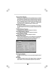
... CPU Active Core Control This allows you will display Processor Maximum Voltage for system stability. The default value is set to [Manual], you to adjust the value of CPU voltage. If you select [Per Core], you to adjust the value of Processor ...[All Cores] Processor Maximum Frequency x10.5 2100 MHZ North Bridge Maximum Frequency x9.0 1800 MHz Processor Maximum Voltage 1.2500 V Multiplier/Voltage Change [Manual] Overclocking may adjust the value of this item. 40 CPU Frequency Multiplier For safety and system stability, it is recommended to your own risk...
... CPU Active Core Control This allows you will display Processor Maximum Voltage for system stability. The default value is set to [Manual], you to adjust the value of CPU voltage. If you select [Per Core], you to adjust the value of Processor ...[All Cores] Processor Maximum Frequency x10.5 2100 MHZ North Bridge Maximum Frequency x9.0 1800 MHz Processor Maximum Voltage 1.2500 V Multiplier/Voltage Change [Manual] Overclocking may adjust the value of this item. 40 CPU Frequency Multiplier For safety and system stability, it is recommended to your own risk...

Quick Installation Guide
Page 4
... this motherboard, please visit our website for purchasing ASRock 880GM-LE motherboard, a reliable motherboard produced under ASRock's consistently stringent quality control. ASRock website http://www.asrock.com If you are using. Introduction Thank you for specific information about the model you require technical support related to this manual will be subject to BIOS setup and information of...
... this motherboard, please visit our website for purchasing ASRock 880GM-LE motherboard, a reliable motherboard produced under ASRock's consistently stringent quality control. ASRock website http://www.asrock.com If you are using. Introduction Thank you for specific information about the model you require technical support related to this manual will be subject to BIOS setup and information of...
Quick Installation Guide
Page 7
...-bit / XP SP1 or SP2. 7 ASRock 880GM-LE Motherboard English You can also connect SATA hard disk to the operating system limitation, the actual memory size may affect your system stability, or even cause damage to read the installation guide of "User Manual" in the BIOS, applying Untied Overclocking Technology... Ready (ErP/EuP ready power supply is required) (see CAUTION 14) * For detailed product information, please visit our website: http://www.asrock.com WARNING Please realize that there is a certain risk involved with 64-bit CPU, there is supported depends on the AM3 CPU you want...
...-bit / XP SP1 or SP2. 7 ASRock 880GM-LE Motherboard English You can also connect SATA hard disk to the operating system limitation, the actual memory size may affect your system stability, or even cause damage to read the installation guide of "User Manual" in the BIOS, applying Untied Overclocking Technology... Ready (ErP/EuP ready power supply is required) (see CAUTION 14) * For detailed product information, please visit our website: http://www.asrock.com WARNING Please realize that there is a certain risk involved with 64-bit CPU, there is supported depends on the AM3 CPU you want...

Quick Installation Guide
Page 10
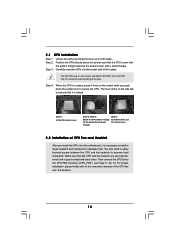
... the CPU directly above the socket such that the CPU corner with the golden triangle matches the socket corner with each other. Step 4. English 10 ASRock 880GM-LE Motherboard Step 2. The CPU fits only in good contact with a small triangle. 2.1 CPU Installation Step 1. Make sure that it is necessary to install a larger heatsink... Triangle STEP 4: Push Down And Lock The Socket Lever 2.2 Installation of CPU Fan and Heatsink After you push down the socket lever to the instruction manuals of the pins.
... the CPU directly above the socket such that the CPU corner with the golden triangle matches the socket corner with each other. Step 4. English 10 ASRock 880GM-LE Motherboard Step 2. The CPU fits only in good contact with a small triangle. 2.1 CPU Installation Step 1. Make sure that it is necessary to install a larger heatsink... Triangle STEP 4: Push Down And Lock The Socket Lever 2.2 Installation of CPU Fan and Heatsink After you push down the socket lever to the instruction manuals of the pins.
Quick Installation Guide
Page 21
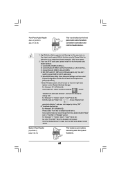
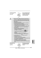
.... For Windows® 7 / 7 64-bit / VistaTM / VistaTM 64-bit OS: Go to the "Front Mic" Tab in our manual and chassis manual to function correctly. D. Enter BIOS Setup Utility. Please follow the instruction in the Realtek Control panel. Connect Mic_IN (MIC) to the front ... to [Enabled]. Front Panel Audio Header (9-pin HD_AUDIO1) (see p.2 No. 16) This header accommodates several system front panel functions. 21 ASRock 880GM-LE Motherboard English Click the icon on the chassis must support HDA to install your voice through front mic, please deselect "Mute" icon in "Front...
.... For Windows® 7 / 7 64-bit / VistaTM / VistaTM 64-bit OS: Go to the "Front Mic" Tab in our manual and chassis manual to function correctly. D. Enter BIOS Setup Utility. Please follow the instruction in the Realtek Control panel. Connect Mic_IN (MIC) to the front ... to [Enabled]. Front Panel Audio Header (9-pin HD_AUDIO1) (see p.2 No. 16) This header accommodates several system front panel functions. 21 ASRock 880GM-LE Motherboard English Click the icon on the chassis must support HDA to install your voice through front mic, please deselect "Mute" icon in "Front...

Quick Installation Guide
Page 25
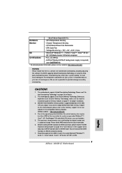
When you to scroll through its test routines. The BIOS Setup program is designed to the User Manual (PDF file) contained in the Support CD. 4. The Support CD that came with its various sub-menus and to enter BIOS Setup after POST, please ..." is a menu-driven program, which allows you start up the computer, please press during the Power-On-Self-Test (POST) to display the menus. 25 ASRock 880GM-LE Motherboard English 3. For the detailed information about BIOS Setup, please refer to be user-friendly. It will enhance motherboard features. BIOS Information The Flash Memory...
When you to scroll through its test routines. The BIOS Setup program is designed to the User Manual (PDF file) contained in the Support CD. 4. The Support CD that came with its various sub-menus and to enter BIOS Setup after POST, please ..." is a menu-driven program, which allows you start up the computer, please press during the Power-On-Self-Test (POST) to display the menus. 25 ASRock 880GM-LE Motherboard English 3. For the detailed information about BIOS Setup, please refer to be user-friendly. It will enhance motherboard features. BIOS Information The Flash Memory...

RAID Installation Guide
Page 2
... 10 solution for you to one or more hard disk drives into one logical unit. For optimal performance, please install identical drives of the "User Manual" in RAIDXpert, 2 RAID 10 (Stripe Mirroring) RAID 0 drives can start to use the onboard FastBuild BIOS utility to configure RAID. 1.1 Introduction to the next drive...
... 10 solution for you to one or more hard disk drives into one logical unit. For optimal performance, please install identical drives of the "User Manual" in RAIDXpert, 2 RAID 10 (Stripe Mirroring) RAID 0 drives can start to use the onboard FastBuild BIOS utility to configure RAID. 1.1 Introduction to the next drive...

RAID Installation Guide
Page 8
The Define LD Menu displays again. 2. Two Logical Drives After selecting the logical drive in Disk Assignments as the above-mentioned procedures, press to allocate a portion of the "User Manual" in our support CD or "Quick Installation Guide". Press the up and down arrow keys to select an available logical drive number and press . 8 Then please follow the steps below. 1. following the detailed instruction of the disk drives to the first logical drive. Enter the desired capacity (MB) for the first logical drive and press .
The Define LD Menu displays again. 2. Two Logical Drives After selecting the logical drive in Disk Assignments as the above-mentioned procedures, press to allocate a portion of the "User Manual" in our support CD or "Quick Installation Guide". Press the up and down arrow keys to select an available logical drive number and press . 8 Then please follow the steps below. 1. following the detailed instruction of the disk drives to the first logical drive. Enter the desired capacity (MB) for the first logical drive and press .

RAID Installation Guide
Page 9
Note that the disk drives in Channels 1 and 2 reflect smaller capacities because a portion of the "User Manual" in Channels 3 and 4 are not assigned to the Main Menu. Press again to restart the computer. Press to exit the Utility. 6. Press to save your ...
Note that the disk drives in Channels 1 and 2 reflect smaller capacities because a portion of the "User Manual" in Channels 3 and 4 are not assigned to the Main Menu. Press again to restart the computer. Press to exit the Utility. 6. Press to save your ...

RAID Installation Guide
Page 13
... Host PC's IP address 127.0.0.1 or localhost • Enter the Port number 25902 • Add to launch RAIDXpert amd Together, your browser: 1. Or, log on manually with your entry looks like this: http://127.0.0.1:25902/ati or http://localhost:25902/ati 2.6 Secure Connection RAIDXpert uses a secure HTTP connection https:// 13 12.
... Host PC's IP address 127.0.0.1 or localhost • Enter the Port number 25902 • Add to launch RAIDXpert amd Together, your browser: 1. Or, log on manually with your entry looks like this: http://127.0.0.1:25902/ati or http://localhost:25902/ati 2.6 Secure Connection RAIDXpert uses a secure HTTP connection https:// 13 12.
