User Manual
Page 4
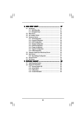
... 60 4.1 Install Operating System 60 4.2 Support CD Information 60 4.2.1 Running Support CD 60 4.2.2 Drivers Menu 60 4.2.3 Utilities Menu 60 4.2.4 Contact Information 60 4 3 . BIOS SETUP UTILITY 37 3.1 Introduction 37 3.1.1 BIOS Menu Bar 37 3.1.2 Navigation Keys 38 3.2 Main Screen 38 3.3 OC Tweaker Screen 39 3.4 Advanced Screen 46 3.4.1 CPU Configuration 47 3.4.2 Chipset Configuration 48 3.4.3 ACPI...
... 60 4.1 Install Operating System 60 4.2 Support CD Information 60 4.2.1 Running Support CD 60 4.2.2 Drivers Menu 60 4.2.3 Utilities Menu 60 4.2.4 Contact Information 60 4 3 . BIOS SETUP UTILITY 37 3.1 Introduction 37 3.1.1 BIOS Menu Bar 37 3.1.2 Navigation Keys 38 3.2 Main Screen 38 3.3 OC Tweaker Screen 39 3.4 Advanced Screen 46 3.4.1 CPU Configuration 47 3.4.2 Chipset Configuration 48 3.4.3 ACPI...
User Manual
Page 5
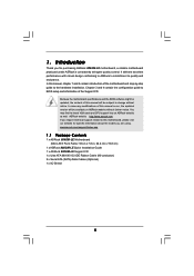
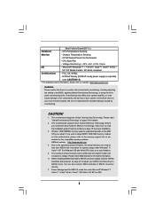
...website for specific information about the model you for purchasing ASRock 880GM-LE motherboard, a reliable motherboard produced under ASRock's consistently stringent quality control. Because the motherboard specifications and the BIOS software might be updated, the content of this manual... BIOS setup and information of this manual will be available on ASRock website as well. www.asrock.com/support/index.asp 1.1 Package Contents 1 x ASRock 880GM-LE Motherboard (Micro ATX Form Factor: 9.6-in x 7.8-in, 24.4 cm x 19.8 cm) 1 x ASRock 880GM-LE Quick Installation Guide 1 x ASRock 880GM-LE ...
...website for specific information about the model you for purchasing ASRock 880GM-LE motherboard, a reliable motherboard produced under ASRock's consistently stringent quality control. Because the motherboard specifications and the BIOS software might be updated, the content of this manual... BIOS setup and information of this manual will be available on ASRock website as well. www.asrock.com/support/index.asp 1.1 Package Contents 1 x ASRock 880GM-LE Motherboard (Micro ATX Form Factor: 9.6-in x 7.8-in, 24.4 cm x 19.8 cm) 1 x ASRock 880GM-LE Quick Installation Guide 1 x ASRock 880GM-LE ...
User Manual
Page 7
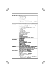
... - Front panel audio connector - 3 x USB 2.0 headers (support 6 USB 2.0 ports) (see CAUTION 12) - Explorer, AMD Fusion, ASRock Software Suite (CyberLink DVD Suite and Creative Sound Blaster X-Fi MB) (OEM and Trial Version) - ACPI 1.1 Compliance Wake Up Events - CPU... Frequency Stepless Control (see CAUTION 7) - 8Mb AMI BIOS - CPU/Chassis/Power FAN connector - 24 pin ATX power connector - 4 pin 12V power connector - AMI Legal BIOS - Supports jumperfree - Rear Panel I/O Connector BIOS Feature Support CD Unique Feature I/O Panel - 1 x PS/2 Mouse Port -...
... - Front panel audio connector - 3 x USB 2.0 headers (support 6 USB 2.0 ports) (see CAUTION 12) - Explorer, AMD Fusion, ASRock Software Suite (CyberLink DVD Suite and Creative Sound Blaster X-Fi MB) (OEM and Trial Version) - ACPI 1.1 Compliance Wake Up Events - CPU... Frequency Stepless Control (see CAUTION 7) - 8Mb AMI BIOS - CPU/Chassis/Power FAN connector - 24 pin ATX power connector - 4 pin 12V power connector - AMI Legal BIOS - Supports jumperfree - Rear Panel I/O Connector BIOS Feature Support CD Unique Feature I/O Panel - 1 x PS/2 Mouse Port -...
User Manual
Page 8
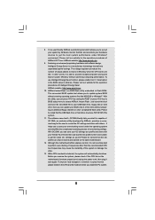
... your system stability, or even cause damage to change. For Windows® OS with overclocking, including adjusting the setting in the BIOS, applying Untied Overclocking Technology, or using the thirdparty overclocking tools. CPU/Chassis/Power Fan Tachometer - Microsoft® Windows® 7... list on page 15 for USB 2.0 works fine under Windows® 7 / VistaTM / XP. Chassis Temperature Sensing - ASRock website http://www.asrock.com 4. CPU Temperature Sensing Monitor - Boot Failure Guard (B.F.G.) Hardware - CPU Quiet Fan - We are not responsible for ...
... your system stability, or even cause damage to change. For Windows® OS with overclocking, including adjusting the setting in the BIOS, applying Untied Overclocking Technology, or using the thirdparty overclocking tools. CPU/Chassis/Power Fan Tachometer - Microsoft® Windows® 7... list on page 15 for USB 2.0 works fine under Windows® 7 / VistaTM / XP. Chassis Temperature Sensing - ASRock website http://www.asrock.com 4. CPU Temperature Sensing Monitor - Boot Failure Guard (B.F.G.) Hardware - CPU Quiet Fan - We are not responsible for ...
User Manual
Page 9
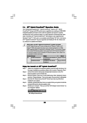
...to surveil your hardware devices to update system BIOS without sacrificing computing performance. OC DNA, an exclusive utility developed by hardware monitor function and overclock your system by ASRock, provides a convenient way for the user to access ASRock Instant Flash. It helps you can update ...software design, Intelligent Energy Saver is detected, the system will automatically shutdown. To use FAT32/16/12 file system. 11. ASRock Instant Flash is a BIOS flash utility embedded in a few clicks without preparing an additional floppy diskette or other words, it back again. OC DNA...
...to surveil your hardware devices to update system BIOS without sacrificing computing performance. OC DNA, an exclusive utility developed by hardware monitor function and overclock your system by ASRock, provides a convenient way for the user to access ASRock Instant Flash. It helps you can update ...software design, Intelligent Energy Saver is detected, the system will automatically shutdown. To use FAT32/16/12 file system. 11. ASRock Instant Flash is a BIOS flash utility embedded in a few clicks without preparing an additional floppy diskette or other words, it back again. OC DNA...
User Manual
Page 11
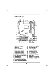
... LINE IN Center: FRONT Bottom: MIC IN LAN AUDIO CODEC Super I/O CD1 1 HD_AUDIO1 LPT1 1 PCIE1 AMD 880G Chipset Hybrid CrossFire PCIE2 880GM-LE IDE1 PWR_FAN1 SATAII_4 SATAII_5 SATAII_6 (PORT 3) (PORT 4) (PORT 5) RoHS PCI1 IR1 1 FLOPPY1 PCI2 USB10_11 1 AMD SB710 Chipset SPEAKER1 1 PLED PWRBTN ...PANEL 1 1 HDLED RESET 8Mb BIOS USB8_9 1 CHA_FAN1 USB6_7 1 SATAII_1 SATAII_2 SATAII_3 (PORT 0) (PORT 1) (PORT 2) 27 26 25 24 23 22 21 2019 18 AT X P W R 1 24...
... LINE IN Center: FRONT Bottom: MIC IN LAN AUDIO CODEC Super I/O CD1 1 HD_AUDIO1 LPT1 1 PCIE1 AMD 880G Chipset Hybrid CrossFire PCIE2 880GM-LE IDE1 PWR_FAN1 SATAII_4 SATAII_5 SATAII_6 (PORT 3) (PORT 4) (PORT 5) RoHS PCI1 IR1 1 FLOPPY1 PCI2 USB10_11 1 AMD SB710 Chipset SPEAKER1 1 PLED PWRBTN ...PANEL 1 1 HDLED RESET 8Mb BIOS USB8_9 1 CHA_FAN1 USB6_7 1 SATAII_1 SATAII_2 SATAII_3 (PORT 0) (PORT 1) (PORT 2) 27 26 25 24 23 22 21 2019 18 AT X P W R 1 24...
User Manual
Page 18
...Display Properties dialog that you wish to the steps below . Set the "Screen Resolution" and "Color Quality" as Secondary. Click "Apply" or "OK" to enter BIOS setup. B. D. Press to apply these new values. For Windows® XP / XP 64-bit OS: Right click the desktop, choose "Properties", and select the .... Click the items "This is no need to save your system. Repeat steps A through E for the second monitor. If you do not adjust the BIOS setup, the default value of VGA/D-sub. Click "OK" to install them again. 5. F. Boot your change. A. 3. C.
...Display Properties dialog that you wish to the steps below . Set the "Screen Resolution" and "Color Quality" as Secondary. Click "Apply" or "OK" to enter BIOS setup. B. D. Press to apply these new values. For Windows® XP / XP 64-bit OS: Right click the desktop, choose "Properties", and select the .... Click the items "This is no need to save your system. Repeat steps A through E for the second monitor. If you do not adjust the BIOS setup, the default value of VGA/D-sub. Click "OK" to install them again. 5. F. Boot your change. A. 3. C.
User Manual
Page 20
... graphics cards, please visit our website for both the onboard VGA and the discrete graphics card. Install one compatible PCI Express graphics card to enter BIOS setup. Step 4. Press to PCIE2 slot (blue). An ATITM Hybrid CrossFireXTM system includes an ATITM RadeonTM 2400 or ATITM RadeonTM 3450 series graphics processor and...
... graphics cards, please visit our website for both the onboard VGA and the discrete graphics card. Install one compatible PCI Express graphics card to enter BIOS setup. Step 4. Press to PCIE2 slot (blue). An ATITM Hybrid CrossFireXTM system includes an ATITM RadeonTM 2400 or ATITM RadeonTM 3450 series graphics processor and...
User Manual
Page 22
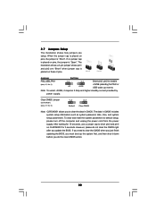
... higher standby current provided by power supply. Note: To select +5VSB, it down before you do not clear the CMOS right after you update the BIOS. After waiting for 15 seconds, use a jumper cap to enable (see p.11, No. 9) 1_2 2_3 Default Clear CMOS Note: CLRCMOS1 allows you to clear... the CMOS when you just finish updating the BIOS, you need to clear the data in CMOS includes system setup information such as system password, date, time, and system setup parameters. However, please do...
... higher standby current provided by power supply. Note: To select +5VSB, it down before you do not clear the CMOS right after you update the BIOS. After waiting for 15 seconds, use a jumper cap to enable (see p.11, No. 9) 1_2 2_3 Default Clear CMOS Note: CLRCMOS1 allows you to clear... the CMOS when you just finish updating the BIOS, you need to clear the data in CMOS includes system setup information such as system password, date, time, and system setup parameters. However, please do...
User Manual
Page 25
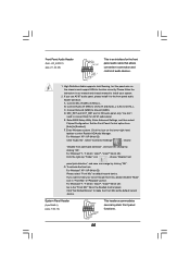
... "Playback" portion. E. F. Please follow the instruction in our manual and chassis manual to MIC2_L. Connect Audio_R (RIN) to OUT2_R and Audio_L (LIN) to [Enabled]. Enter BIOS Setup Utility. Enter Windows system. To activate the front mic. High Definition Audio supports Jack Sensing, but the panel wire on the lower right hand...
... "Playback" portion. E. F. Please follow the instruction in our manual and chassis manual to MIC2_L. Connect Audio_R (RIN) to OUT2_R and Audio_L (LIN) to [Enabled]. Enter BIOS Setup Utility. Enter Windows system. To activate the front mic. High Definition Audio supports Jack Sensing, but the panel wire on the lower right hand...
User Manual
Page 32
... the message on a RAID disk composed of 2 or more SATA / SATAII HDDs with RAID functions, please follow below steps. A. B. A. Insert the ASRock Support CD into the floppy diskette. 32 C. Please follow below procedures according to the OS you install. 2.14.1 Installing Windows® XP / XP 64... drivers. B. During POST at the beginning of 2 or more SATA / SATAII HDDs with RAID functions, please follow the order from up BIOS. Then you see these messages, Please insert a blank formatted diskette into floppy drive A: press any key to start to format the floppy...
... the message on a RAID disk composed of 2 or more SATA / SATAII HDDs with RAID functions, please follow below steps. A. B. A. Insert the ASRock Support CD into the floppy diskette. 32 C. Please follow below procedures according to the OS you install. 2.14.1 Installing Windows® XP / XP 64... drivers. B. During POST at the beginning of 2 or more SATA / SATAII HDDs with RAID functions, please follow the order from up BIOS. Then you see these messages, Please insert a blank formatted diskette into floppy drive A: press any key to start to format the floppy...
User Manual
Page 33
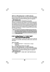
... 4: Install Windows® XP / XP 64-bit OS on your system. After reading the floppy disk, the driver will be presented. Enter BIOS SETUP UTILITY Advanced screen Storage Configuration. STEP 2: Use "RAID Installation Guide" to manage (create, convert, delete, or rebuild) RAID functions on ...RAID Installation Guide 2.14.2 Installing Windows® 7 / 7 64-bit / VistaTM / VistaTM 64-bit With RAID Functions If you need to the BIOS RAID installation guide part of 2 or more SATA / SATAII HDDs with RAID functions, please follow below steps. Please refer to check the RAID installation ...
... 4: Install Windows® XP / XP 64-bit OS on your system. After reading the floppy disk, the driver will be presented. Enter BIOS SETUP UTILITY Advanced screen Storage Configuration. STEP 2: Use "RAID Installation Guide" to manage (create, convert, delete, or rebuild) RAID functions on ...RAID Installation Guide 2.14.2 Installing Windows® 7 / 7 64-bit / VistaTM / VistaTM 64-bit With RAID Functions If you need to the BIOS RAID installation guide part of 2 or more SATA / SATAII HDDs with RAID functions, please follow below steps. Please refer to check the RAID installation ...
User Manual
Page 34
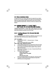
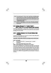
... follow below procedures according to install Windows® XP / XP 64-bit on your system. Then, please set up "SATA Operation Mode" to [IDE] in BIOS. 2.15 Installing Windows® 7 / 7 64-bit / VistaTM / VistaTM 64-bit / XP / XP 64-bit Without RAID Functions If you want to install Windows® ... device used, please set up "SATA Operation Mode" to set the RAID configuration by using the Windows RAID installation guide in the following path in BIOS first. Currently, if you install Windows® 7 / 7 64-bit / VistaTM / VistaTM 64-bit on SATA / SATAII HDDs, you still need to [...
... follow below procedures according to install Windows® XP / XP 64-bit on your system. Then, please set up "SATA Operation Mode" to [IDE] in BIOS. 2.15 Installing Windows® 7 / 7 64-bit / VistaTM / VistaTM 64-bit / XP / XP 64-bit Without RAID Functions If you want to install Windows® ... device used, please set up "SATA Operation Mode" to set the RAID configuration by using the Windows RAID installation guide in the following path in BIOS first. Currently, if you install Windows® 7 / 7 64-bit / VistaTM / VistaTM 64-bit on SATA / SATAII HDDs, you still need to [...
User Manual
Page 35
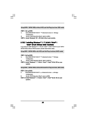
...Storage Configuration. Using SATA / SATAII HDDs without NCQ and Hot Plug functions (IDE mode) STEP 1: Set up BIOS. B. Using SATA / SATAII HDDs without NCQ and Hot Plug functions (IDE mode) STEP 1: Set up BIOS. A. STEP 2: Install Windows® 7 / 7 64-bit / VistaTM / VistaTM 64-bit OS on ... Set the "SATA Operation Mode" option to install Windows® 7 / 7 64-bit / VistaTM / VistaTM 64-bit on your system. 35 Enter BIOS SETUP UTILITY Advanced screen Storage Configuration. B. A. STEP 2: Install Windows® XP / XP 64-bit OS on your system. Enter...
...Storage Configuration. Using SATA / SATAII HDDs without NCQ and Hot Plug functions (IDE mode) STEP 1: Set up BIOS. B. Using SATA / SATAII HDDs without NCQ and Hot Plug functions (IDE mode) STEP 1: Set up BIOS. A. STEP 2: Install Windows® 7 / 7 64-bit / VistaTM / VistaTM 64-bit OS on ... Set the "SATA Operation Mode" option to install Windows® 7 / 7 64-bit / VistaTM / VistaTM 64-bit on your system. 35 Enter BIOS SETUP UTILITY Advanced screen Storage Configuration. B. A. STEP 2: Install Windows® XP / XP 64-bit OS on your system. Enter...
User Manual
Page 36
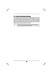
... untied during overclocking, FSB enjoys better margin due to fixed PCI / PCIE buses. Before you enable Untied Overclocking function, please enter "Overclock Mode" option of BIOS setup to set the selection from [Auto] to the warning on page 8 for the possible overclocking risk before you apply Untied Overclocking Technology. 36
... untied during overclocking, FSB enjoys better margin due to fixed PCI / PCIE buses. Before you enable Untied Overclocking function, please enter "Overclock Mode" option of BIOS setup to set the selection from [Auto] to the warning on page 8 for the possible overclocking risk before you apply Untied Overclocking Technology. 36

User Manual
Page 37
... turning the system off and then back on. You may also restart by pressing the reset button on the motherboard stores the BIOS SETUP UTILITY. Because the BIOS software is constantly being updated, the following selections: Main To set up the system time/date information OC Tweaker To set up...Security To set up the computer. Please press or during the Power-On-Self-Test (POST) to enter the BIOS SETUP UTILITY, otherwise, POST will continue with the following BIOS setup screens and descriptions are for reference purpose only, and they may not exactly match what you start up the...
... turning the system off and then back on. You may also restart by pressing the reset button on the motherboard stores the BIOS SETUP UTILITY. Because the BIOS software is constantly being updated, the following selections: Main To set up the system time/date information OC Tweaker To set up...Security To set up the computer. Please press or during the Power-On-Self-Test (POST) to enter the BIOS SETUP UTILITY, otherwise, POST will continue with the following BIOS setup screens and descriptions are for reference purpose only, and they may not exactly match what you start up the...
User Manual
Page 38
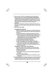
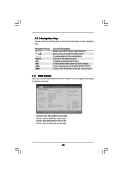
... UTILITY Main OC Tweaker Advanced H/W Monitor System Overview System Time System Date [17:00:09] [Mon 04/12/2010] BIOS Version : 880GM-LE P1.0 Processor Type : AMD Phenom(tm) II X3 720 Processor (64bit) Processor Speed : 2800MHz Microcode Update : 100F42/1000086 L1 Cache Size : 384KB L2 Cache Size : ..., American Megatrends, Inc. Use [+] or [-] to select a field. 3.1.2 Navigation Keys Please check the following table for all the settings To save changes and exit the BIOS SETUP UTILITY To jump to the Exit Screen or exit the current screen 3.2 Main Screen When you enter the...
... UTILITY Main OC Tweaker Advanced H/W Monitor System Overview System Time System Date [17:00:09] [Mon 04/12/2010] BIOS Version : 880GM-LE P1.0 Processor Type : AMD Phenom(tm) II X3 720 Processor (64bit) Processor Speed : 2800MHz Microcode Update : 100F42/1000086 L1 Cache Size : 384KB L2 Cache Size : ..., American Megatrends, Inc. Use [+] or [-] to select a field. 3.1.2 Navigation Keys Please check the following table for all the settings To save changes and exit the BIOS SETUP UTILITY To jump to the Exit Screen or exit the current screen 3.2 Main Screen When you enter the...
User Manual
Page 39
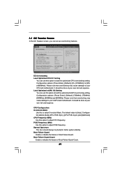
... and Exit ESC Exit v02.54 (C) Copyright 1985-2005, American Megatrends, Inc. Boot Failure Guard Count Enable or disable the feature of Boot Failure Guard. BIOS SETUP UTILITY Main OC Tweaker Advanced H/W Monitor Boot Security Exit EZ Overclocking Load Optimized CPU OC Setting [Press Enter] Load Optimized mGPU OC Setting [Press...
... and Exit ESC Exit v02.54 (C) Copyright 1985-2005, American Megatrends, Inc. Boot Failure Guard Count Enable or disable the feature of Boot Failure Guard. BIOS SETUP UTILITY Main OC Tweaker Advanced H/W Monitor Boot Security Exit EZ Overclocking Load Optimized CPU OC Setting [Press Enter] Load Optimized mGPU OC Setting [Press...
User Manual
Page 40
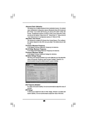
... see the option "Value (All Cores)". Configuration options: [+12%] to [-12%]. CPU Active Core Control This allows you to adjust the value of CPU voltage. BIOS SETUP UTILITY Main OC Tweaker Advanced H/W Monitor Boot Security Exit EZ Overclocking Load Optimized CPU OC Setting [Press Enter] Load Optimized mGPU OC Setting [Press...
... see the option "Value (All Cores)". Configuration options: [+12%] to [-12%]. CPU Active Core Control This allows you to adjust the value of CPU voltage. BIOS SETUP UTILITY Main OC Tweaker Advanced H/W Monitor Boot Security Exit EZ Overclocking Load Optimized CPU OC Setting [Press Enter] Load Optimized mGPU OC Setting [Press...
User Manual
Page 41
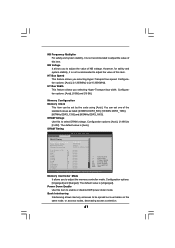
... options: [Auto], [x1 200MHz] to be set one of the standard values as listed: [400MHz DDR3_800], [533MHz DDR3_1066], [667MHz DDR3_1333] and [800MHz DDR3_1600]. DRAM Timing BIOS SETUP UTILITY OC Tweaker DRAM Timing Memory Controller Mode Power Down Enable Bank Interleaving Channel Interleaving CAS Latency (CL) 9 TRCD 12 TRP 12 TRAS 30...
... options: [Auto], [x1 200MHz] to be set one of the standard values as listed: [400MHz DDR3_800], [533MHz DDR3_1066], [667MHz DDR3_1333] and [800MHz DDR3_1600]. DRAM Timing BIOS SETUP UTILITY OC Tweaker DRAM Timing Memory Controller Mode Power Down Enable Bank Interleaving Channel Interleaving CAS Latency (CL) 9 TRCD 12 TRP 12 TRAS 30...


