User Manual
Page 6
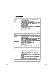
..., CrossFireXTM and Hybrid CrossFireXTM - DX10.1 class iGPU, Shader Model 4.1 - Three VGA Output options: D-Sub, DVI-D and HDMI - Support for Socket AM3+ processors - Supports Hyper-Transport 3.0 (HT 3.0) Technology - Support DDR3 1866(OC)/1800(OC)/1600(OC)/1333/1066/800 non-ECC, un-...9.6-in, 30.5 cm x 24.4 cm - Supports 8-Core CPU - Supports CPU up to 140W - Supports AMD's Cool 'n' QuietTM Technology - Northbridge: AMD 880G - Supports D-Sub with DVI and HDMI ports 6 FSB 2600 MHz (5.2 GT/s) - Max. resolution up to 2560x1600 @ 75Hz - resolution up to 2048x1536 @...
..., CrossFireXTM and Hybrid CrossFireXTM - DX10.1 class iGPU, Shader Model 4.1 - Three VGA Output options: D-Sub, DVI-D and HDMI - Support for Socket AM3+ processors - Supports Hyper-Transport 3.0 (HT 3.0) Technology - Support DDR3 1866(OC)/1800(OC)/1600(OC)/1333/1066/800 non-ECC, un-...9.6-in, 30.5 cm x 24.4 cm - Supports 8-Core CPU - Supports CPU up to 140W - Supports AMD's Cool 'n' QuietTM Technology - Northbridge: AMD 880G - Supports D-Sub with DVI and HDMI ports 6 FSB 2600 MHz (5.2 GT/s) - Max. resolution up to 2560x1600 @ 75Hz - resolution up to 2048x1536 @...
User Manual
Page 12
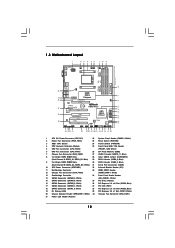
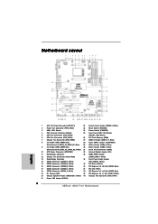
...3.0 T: USB0 B: USB1 LAN PHY RJ-45 LAN Top: LINE IN Top: CTR BASS CHA_FAN1 PCIE1 AMD 880G Chipset PCI Express 2.0 PCIE2 USB 3.0 Hybrid CrossFire CMOS BATTERY 880G Pro3 CHA_FAN3 Designed in Taipei Super I/O PCI1 PCIE3 ErP/EuP Ready AUDIO CODEC PCI2 RoHS PCI3 HD_AUDIO1 IR1 HDMI_SPDIF1 ...12V Power Connector (ATX12V1) 22 System Panel Header (PANEL1, White) 2 Power Fan Connector (PWR_FAN1) 23 Reset Switch (RSTBTN) 3 AM3+ CPU Socket 24 Power Switch (PWRBTN) 4 CPU Heatsink Retention Module 25 Front Panel IEEE 1394 Header 5 CPU Fan Connector (CPU_FAN2) (FRONT_1394, White) 6...
...3.0 T: USB0 B: USB1 LAN PHY RJ-45 LAN Top: LINE IN Top: CTR BASS CHA_FAN1 PCIE1 AMD 880G Chipset PCI Express 2.0 PCIE2 USB 3.0 Hybrid CrossFire CMOS BATTERY 880G Pro3 CHA_FAN3 Designed in Taipei Super I/O PCI1 PCIE3 ErP/EuP Ready AUDIO CODEC PCI2 RoHS PCI3 HD_AUDIO1 IR1 HDMI_SPDIF1 ...12V Power Connector (ATX12V1) 22 System Panel Header (PANEL1, White) 2 Power Fan Connector (PWR_FAN1) 23 Reset Switch (RSTBTN) 3 AM3+ CPU Socket 24 Power Switch (PWRBTN) 4 CPU Heatsink Retention Module 25 Front Panel IEEE 1394 Header 5 CPU Fan Connector (CPU_FAN2) (FRONT_1394, White) 6...

User Manual
Page 15
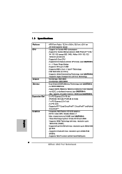
... you install the motherboard, study the configuration of the following precautions before you install or remove any component. 2. Installation This is detached from the wall socket before touching any component, ensure that the power is switched off or the power cord is an ATX form factor (12.0-in x 9.6-in the bag...
... you install the motherboard, study the configuration of the following precautions before you install or remove any component. 2. Installation This is detached from the wall socket before touching any component, ensure that the power is switched off or the power cord is an ATX form factor (12.0-in x 9.6-in the bag...
User Manual
Page 16
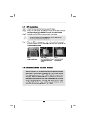
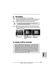
...No. 5). Step 3. Step 4. Then connect the CPU fan to improve heat dissipation. Position the CPU directly above the socket such that the CPU corner with the golden triangle matches the socket corner with each other. DO NOT force the CPU into this motherboard, it fits in place, press it firmly on...the instruction manuals of the pins. Make sure that it is in place. The lever clicks on the socket while you install the CPU into the socket to a 90o angle. Unlock the socket by lifting the lever up to avoid bending of the CPU fan and the heatsink. 16 For proper ...
...No. 5). Step 3. Step 4. Then connect the CPU fan to improve heat dissipation. Position the CPU directly above the socket such that the CPU corner with the golden triangle matches the socket corner with each other. DO NOT force the CPU into this motherboard, it fits in place, press it firmly on...the instruction manuals of the pins. Make sure that it is in place. The lever clicks on the socket while you install the CPU into the socket to a 90o angle. Unlock the socket by lifting the lever up to avoid bending of the CPU fan and the heatsink. 16 For proper ...
Quick Installation Guide
Page 2
... Header (PLED1) 2 ASRock 880G Pro3 Motherboard Blue) 17 SATA3 Connector (SATAIII_1, White) 37 PCI Slot (PCI1) 18 SATA3 Connector (SATA3_5, White) 38 PCI Express 2.0 x16 Slot (PCIE2; Motherboard Layout English 1 ATX 12V Power Connector (ATX12V1) 22 System Panel Header (PANEL1, White) 2 Power Fan Connector (PWR_FAN1) 23 Reset Switch (RSTBTN) 3 AM3+ CPU Socket 24 Power...
... Header (PLED1) 2 ASRock 880G Pro3 Motherboard Blue) 17 SATA3 Connector (SATAIII_1, White) 37 PCI Slot (PCI1) 18 SATA3 Connector (SATA3_5, White) 38 PCI Express 2.0 x16 Slot (PCIE2; Motherboard Layout English 1 ATX 12V Power Connector (ATX12V1) 22 System Panel Header (PANEL1, White) 2 Power Fan Connector (PWR_FAN1) 23 Reset Switch (RSTBTN) 3 AM3+ CPU Socket 24 Power...
Quick Installation Guide
Page 6
... graphics - Three VGA Output options: D-Sub, DVI-D and HDMI - resolution up to 2560x1600 @ 75Hz - Support for Socket AM3+ processors - Supports 8-Core CPU - Supports Untied Overclocking Technology (see CAUTION 6) - resolution up to 2048x1536 @ 85Hz...880G - Dual Channel DDR3 Memory Technology (see CAUTION 5) - 2 x PCI Express 2.0 x16 slot (PCIE2 @ x16 mode; capacity of system memory: 32GB (see CAUTION 3) - 4 x DDR3 DIMM slots - Supports ATITM Quad CrossFireXTM, CrossFireXTM and Hybrid CrossFireXTM - Supports D-Sub with DVI and HDMI ports English 6 ASRock 880G Pro3...
... graphics - Three VGA Output options: D-Sub, DVI-D and HDMI - resolution up to 2560x1600 @ 75Hz - Support for Socket AM3+ processors - Supports 8-Core CPU - Supports Untied Overclocking Technology (see CAUTION 6) - resolution up to 2048x1536 @ 85Hz...880G - Dual Channel DDR3 Memory Technology (see CAUTION 5) - 2 x PCI Express 2.0 x16 slot (PCIE2 @ x16 mode; capacity of system memory: 32GB (see CAUTION 3) - 4 x DDR3 DIMM slots - Supports ATITM Quad CrossFireXTM, CrossFireXTM and Hybrid CrossFireXTM - Supports D-Sub with DVI and HDMI ports English 6 ASRock 880G Pro3...

Quick Installation Guide
Page 12
... the ICs. 4. 2. Installation This is detached from the wall socket before touching any component, ensure that comes with the component. 5. Unplug the power cord from the power supply. Hold components by the edges and do so may damage the motherboard. 12 ASRock 880G Pro3 Motherboard English Before you handle components. 3. To avoid damaging the...
... the ICs. 4. 2. Installation This is detached from the wall socket before touching any component, ensure that comes with the component. 5. Unplug the power cord from the power supply. Hold components by the edges and do so may damage the motherboard. 12 ASRock 880G Pro3 Motherboard English Before you handle components. 3. To avoid damaging the...
Quick Installation Guide
Page 13
.../ STEP 3: Match The CPU Golden Triangle To The Socket Corner Small Triangle STEP 4: Push Down And Lock The Socket Lever 2.2 Installation of the pins. English 13 ASRock 880G Pro3 Motherboard Position the CPU directly above the socket such that it fits in one correct orientation. Carefully insert... the CPU into the socket until it is in good contact with...
.../ STEP 3: Match The CPU Golden Triangle To The Socket Corner Small Triangle STEP 4: Push Down And Lock The Socket Lever 2.2 Installation of the pins. English 13 ASRock 880G Pro3 Motherboard Position the CPU directly above the socket such that it fits in one correct orientation. Carefully insert... the CPU into the socket until it is in good contact with...