
RAID Installation Guide
Page 1
... RAID Installation Guide 10 2.1 Components of RAIDXpert Installation Software 10 2.2 Browser Support 10 2.3 Installing RAIDXpert 10 2.4 Logging into RAIDXpert 13 2.5 Regular Connection 13 2.6 Secure Connection 13 2.7 Creating a New Logical Drive 14 2.8 Connecting to RAID 2 1.2 RAID Configurations Precautions 3 1.3 Installing Windows 7 / 7 64-bit / Vista / Vista 64-bit / XP / XP 64-bit With RAID...Disk Array 5 2. AMD RAID Installation Guide 1. AMD BIOS RAID Installation Guide 2 1.1 Introduction to RAIDXpert from the Internet 17 2.9 Running RAIDXpert without Network Connection 17 1
... RAID Installation Guide 10 2.1 Components of RAIDXpert Installation Software 10 2.2 Browser Support 10 2.3 Installing RAIDXpert 10 2.4 Logging into RAIDXpert 13 2.5 Regular Connection 13 2.6 Secure Connection 13 2.7 Creating a New Logical Drive 14 2.8 Connecting to RAID 2 1.2 RAID Configurations Precautions 3 1.3 Installing Windows 7 / 7 64-bit / Vista / Vista 64-bit / XP / XP 64-bit With RAID...Disk Array 5 2. AMD RAID Installation Guide 1. AMD BIOS RAID Installation Guide 2 1.1 Introduction to RAIDXpert from the Internet 17 2.9 Running RAIDXpert without Network Connection 17 1

RAID Installation Guide
Page 12
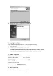
... a default certificate for the server as well as for the RAIDXpert applications you are installing. For example, the Windows default folder is better to all connections involving the Internet or outside your choice. 11. However, in some cases it is : C:\Program Files\AMD\RAIDXpert If you can choose External Security. And...
... a default certificate for the server as well as for the RAIDXpert applications you are installing. For example, the Windows default folder is better to all connections involving the Internet or outside your choice. 11. However, in some cases it is : C:\Program Files\AMD\RAIDXpert If you can choose External Security. And...
RAID Installation Guide
Page 13
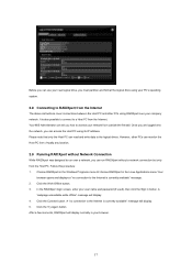
... menu. Launch the Browser. 2. If you did not choose the External Security option during RAIDXpert installation, use the Regular connection. In the Browser address field, type the entry explained below. Or, log on manually with your entry looks like this...127.0.0.1:25902/ati or http://localhost:25902/ati 2.6 Secure Connection RAIDXpert uses a secure HTTP connection https:// 13 If you chose the External Security option during RAIDXpert installation, use the Secure connection. 2.5 Regular Connection RAIDXpert uses an HTTP connection http:// • Enter the Host PC's IP address...
... menu. Launch the Browser. 2. If you did not choose the External Security option during RAIDXpert installation, use the Regular connection. In the Browser address field, type the entry explained below. Or, log on manually with your entry looks like this...127.0.0.1:25902/ati or http://localhost:25902/ati 2.6 Secure Connection RAIDXpert uses a secure HTTP connection https:// 13 If you chose the External Security option during RAIDXpert installation, use the Secure connection. 2.5 Regular Connection RAIDXpert uses an HTTP connection http:// • Enter the Host PC's IP address...
RAID Installation Guide
Page 17
...Programs menu.Or choose RAIDXpert in button. Once you are logged onto the network, you how to the logical drives. Click the Connect button. Your MIS Administrator can tell you can read and write data to access your company network. A "webpage unavailable while offline"... and password (if used), then click the Sign in the Linux Applications menu.Your browser opens and displays a "no connection to run RAIDXpert without Network Connection While RAIDXpert was designed to the Internet is currently available" message. 2. Click the Try Again button. After a few moments...
...Programs menu.Or choose RAIDXpert in button. Once you are logged onto the network, you how to the logical drives. Click the Connect button. Your MIS Administrator can tell you can read and write data to access your company network. A "webpage unavailable while offline"... and password (if used), then click the Sign in the Linux Applications menu.Your browser opens and displays a "no connection to run RAIDXpert without Network Connection While RAIDXpert was designed to the Internet is currently available" message. 2. Click the Try Again button. After a few moments...
User Manual
Page 9
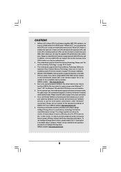
... you can support this motherboard, please refer to enjoy an instant performance boost. It is no such limitation. 6. ASRock website: http://www.asrock.com 8. This motherboard supports Untied Overclocking Technology. If you implement Dual Channel Memory Technology, make sure to adopt DDR3.... Before you want to read "Untied Overclocking Technology" on our website for proper installation. 4. Please visit our website for proper connection. 7. To use Intelligent Energy Saver function, please enable Cool 'n' Quiet option in the BIOS setup in addition, not every AM3...
... you can support this motherboard, please refer to enjoy an instant performance boost. It is no such limitation. 6. ASRock website: http://www.asrock.com 8. This motherboard supports Untied Overclocking Technology. If you implement Dual Channel Memory Technology, make sure to adopt DDR3.... Before you want to read "Untied Overclocking Technology" on our website for proper installation. 4. Please visit our website for proper connection. 7. To use Intelligent Energy Saver function, please enable Cool 'n' Quiet option in the BIOS setup in addition, not every AM3...

User Manual
Page 12
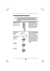
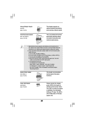
... speaker's plug into "Front Speaker Jack". Choose "2CH", "4CH", "6CH", or "8CH" and then you need to connect a front panel audio cable to the front panel audio header. 1 . 4 I/O Panel 1 23 4 7 5 8 6 9 17 16 15 14 1 USB 2.0 Ports (USB01) 2 USB ...Description Status Description ACT/LINK SPEED LED LED Off No Link Off 10Mbps connection Blinking Data Activity Orange 100Mbps connection On Link Green 1Gbps connection LAN Port ** If you use. See the table below for Audio Output Connection Audio Output Channels Front Speaker Rear Speaker Central / Bass Line In (...
... speaker's plug into "Front Speaker Jack". Choose "2CH", "4CH", "6CH", or "8CH" and then you need to connect a front panel audio cable to the front panel audio header. 1 . 4 I/O Panel 1 23 4 7 5 8 6 9 17 16 15 14 1 USB 2.0 Ports (USB01) 2 USB ...Description Status Description ACT/LINK SPEED LED LED Off No Link Off 10Mbps connection Blinking Data Activity Orange 100Mbps connection On Link Green 1Gbps connection LAN Port ** If you use. See the table below for Audio Output Connection Audio Output Channels Front Speaker Rear Speaker Central / Bass Line In (...
User Manual
Page 14
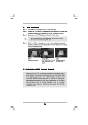
... CPU into the socket until it is necessary to install a larger heatsink and cooling fan to indicate that it is in one correct orientation. Then connect the CPU fan to a 90o angle. Position the CPU directly above the socket such that the CPU and the heatsink are securely fastened and in...
... CPU into the socket until it is necessary to install a larger heatsink and cooling fan to indicate that it is in one correct orientation. Then connect the CPU fan to a 90o angle. Position the CPU directly above the socket such that the CPU and the heatsink are securely fastened and in...
User Manual
Page 17
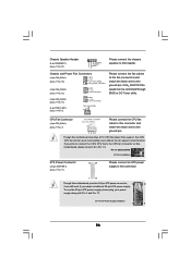
Please connect a chassis fan to motherboard chassis fan connector (CHA_FAN1, CHA_FAN2 or CHA_FAN3) when using multiple graphics cards for the card before you intend to support CrossFireXTM ...
Please connect a chassis fan to motherboard chassis fan connector (CHA_FAN1, CHA_FAN2 or CHA_FAN3) when using multiple graphics cards for the card before you intend to support CrossFireXTM ...
User Manual
Page 19
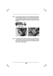
... slot. (You may use the DVI to D-Sub adapter to convert the DVI connector to D-Sub interface, and then connect the D-Sub monitor cable to the DVI to D-Sub adapter.) 19 Step 2. Connect the DVI monitor cable to your graphics card vendor for details.) CrossFire Bridge or Step 3. Please refer to the...
... slot. (You may use the DVI to D-Sub adapter to convert the DVI connector to D-Sub interface, and then connect the D-Sub monitor cable to the DVI to D-Sub adapter.) 19 Step 2. Connect the DVI monitor cable to your graphics card vendor for details.) CrossFire Bridge or Step 3. Please refer to the...
User Manual
Page 24
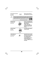
The current SATA3 interface allows up to the SATA3 hard disk or the SATA3 connector on this motherboard. Each USB 2.0 header can be connected to 6.0 Gb/s data transfer rate. Placing jumper caps over these headers and connectors. Serial ATA3 Connectors (SATA3_1: see p.11, No. 20) (SATA3_2_3: see p.11, No. ...
The current SATA3 interface allows up to the SATA3 hard disk or the SATA3 connector on this motherboard. Each USB 2.0 header can be connected to 6.0 Gb/s data transfer rate. Placing jumper caps over these headers and connectors. Serial ATA3 Connectors (SATA3_1: see p.11, No. 20) (SATA3_2_3: see p.11, No. ...
User Manual
Page 25
...to OUT2_L. The LED is on the chassis must support HDA to function correctly. The LED is operating. Connect Audio_R (RIN) to OUT2_R and Audio_L (LIN) to connect them for AC'97 audio panel. Connect Ground (GND) to install your system. 2. For Windows® XP / XP 64-bit OS: ... the "FrontMic" Tab in our manual and chassis manual to Ground (GND). MIC_RET and OUT_RET are for the front panel audio cable that allows convenient connection and control of audio devices. 1. For Windows® 7 / 7 64-bit / VistaTM / VistaTM 64-bit OS: Go to the front panel audio header...
...to OUT2_L. The LED is on the chassis must support HDA to function correctly. The LED is operating. Connect Audio_R (RIN) to OUT2_R and Audio_L (LIN) to connect them for AC'97 audio panel. Connect Ground (GND) to install your system. 2. For Windows® XP / XP 64-bit OS: ... the "FrontMic" Tab in our manual and chassis manual to Ground (GND). MIC_RET and OUT_RET are for the front panel audio cable that allows convenient connection and control of audio devices. 1. For Windows® 7 / 7 64-bit / VistaTM / VistaTM 64-bit OS: Go to the front panel audio header...
User Manual
Page 26
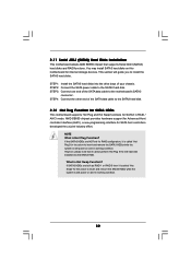
...Though this motherboard provides 24-pin ATX power connector, 12 24 it to Pin 1-3. CHA_FAN1/2/3 fan speed can work if you plan to connect the 3-Pin CPU fan to the CPU fan connector on this motherboard provides 4-Pin CPU fan (Quiet Fan) support, the 3-Pin CPU ...12V CHA_FAN_SPEED FAN_SPEED_CONTROL (3-pin CHA_FAN2) (see p.11 No. 12) (3-pin CHA_FAN3) (see p.11 No. 13) (3-pin PWR_FAN1) (see p.11 No. 7) 1 2 3 4 Please connect the CPU fan cable to this header. CPU Fan Connector (4-pin CPU_FAN1) (see p.11 No. 6) GND +12V CHA_FAN_SPEED GND +12V CHA_FAN_SPEED PWR_FAN_SPEED +12V GND Please...
...Though this motherboard provides 24-pin ATX power connector, 12 24 it to Pin 1-3. CHA_FAN1/2/3 fan speed can work if you plan to connect the 3-Pin CPU fan to the CPU fan connector on this motherboard provides 4-Pin CPU fan (Quiet Fan) support, the 3-Pin CPU ...12V CHA_FAN_SPEED FAN_SPEED_CONTROL (3-pin CHA_FAN2) (see p.11 No. 12) (3-pin CHA_FAN3) (see p.11 No. 13) (3-pin PWR_FAN1) (see p.11 No. 7) 1 2 3 4 Please connect the CPU fan cable to this header. CPU Fan Connector (4-pin CPU_FAN1) (see p.11 No. 6) GND +12V CHA_FAN_SPEED GND +12V CHA_FAN_SPEED PWR_FAN_SPEED +12V GND Please...
User Manual
Page 27
... Header (2-pin HDMI_SPDIF1) (see p.11 No. 33) 1 GND SPDIFOUT HDMI_SPDIF header, providing SPDIF audio output to HDMI VGA card, allows the system to connect HDMI Digital TV/ projector/LCD devices. To use the 4-pin ATX power supply, please plug your power supply along with Pin 1 and Pin 5. 8 ...is one IEEE 1394 header (FRONT_1394) on this motherboard provides 8-pin ATX 12V power connector, it can support one IEEE 1394 port. Please connect the HDMI_SPDIF connector of HDMI VGA card to this connector. This IEEE 1394 header can still work if you adopt a traditional 4-pin ATX 12V...
... Header (2-pin HDMI_SPDIF1) (see p.11 No. 33) 1 GND SPDIFOUT HDMI_SPDIF header, providing SPDIF audio output to HDMI VGA card, allows the system to connect HDMI Digital TV/ projector/LCD devices. To use the 4-pin ATX power supply, please plug your power supply along with Pin 1 and Pin 5. 8 ...is one IEEE 1394 header (FRONT_1394) on this motherboard provides 8-pin ATX 12V power connector, it can support one IEEE 1394 port. Please connect the HDMI_SPDIF connector of HDMI VGA card to this connector. This IEEE 1394 header can still work if you adopt a traditional 4-pin ATX 12V...
User Manual
Page 32
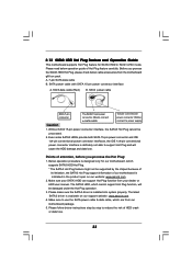
... Interface (AHCI), a new programming interface for SATA host controllers developed thru a joint industry effort. This section will guide you to the SATA3 hard disk. STEP 3: Connect one end of the SATA data cable to the SATA3 hard disk. 2.12 Hot Plug Function for SATA3 HDDs This motherboard supports Hot Plug and... cannot perform Hot Plug if the OS has been installed into the drive bays of the SATA data cable to the motherboard's SATA3 connector. STEP 4: Connect the other end of your chassis. If the SATA3 HDDs are built as RAID 1 or RAID 5 then it is called "Hot Plug" for the action...
... Interface (AHCI), a new programming interface for SATA host controllers developed thru a joint industry effort. This section will guide you to the SATA3 hard disk. STEP 3: Connect one end of the SATA data cable to the SATA3 hard disk. 2.12 Hot Plug Function for SATA3 HDDs This motherboard supports Hot Plug and... cannot perform Hot Plug if the OS has been installed into the drive bays of the SATA data cable to the motherboard's SATA3 connector. STEP 4: Connect the other end of your chassis. If the SATA3 HDDs are built as RAID 1 or RAID 5 then it is called "Hot Plug" for the action...
User Manual
Page 33
...risk of attention, before you process the SATA3 HDD Hot Plug, please check below operation guide of our motherboard is available on our website: www.asrock.com 2. The latest SATA3 driver is indicated in RAID / AHCI mode. Make sure to power supply 1. 2.13 SATA3 HDD Hot Plug Feature and... connector (White) connect to use the SATA power cable & data cable, which cannot support Hot Plug function, will cause the HDD damage and data loss. Please make sure the SATA3 driver is designed only for SATA3 HDD in the product spec on our support website: www.asrock.com 4. The ...
...risk of attention, before you process the SATA3 HDD Hot Plug, please check below operation guide of our motherboard is available on our website: www.asrock.com 2. The latest SATA3 driver is indicated in RAID / AHCI mode. Make sure to power supply 1. 2.13 SATA3 HDD Hot Plug Feature and... connector (White) connect to use the SATA power cable & data cable, which cannot support Hot Plug function, will cause the HDD damage and data loss. Please make sure the SATA3 driver is designed only for SATA3 HDD in the product spec on our support website: www.asrock.com 4. The ...
User Manual
Page 34
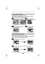
...Hot Unplug: Please do follow below instruction sequence to the power supply 1x4-pin cable. SATA power cable 1x4-pin power connector (White) Step 3 Connect SATA 15-pin power cable connector (Black) end to the SATA3 HDD. Step 2 Unplug SATA 15-pin power cable connector (Black) from SATA3 ... damage and data loss. Step 1 Unplug SATA data cable from SATA3 HDD side. 34 Step 4 Connect SATA data cable to SATA3 HDD. Step 1 Please connect SATA power cable 1x4-pin end Step 2 Connect SATA data cable to (White) to process the Hot Plug, improper procedure will cause the SATA3 HDD...
...Hot Unplug: Please do follow below instruction sequence to the power supply 1x4-pin cable. SATA power cable 1x4-pin power connector (White) Step 3 Connect SATA 15-pin power cable connector (Black) end to the SATA3 HDD. Step 2 Unplug SATA 15-pin power cable connector (Black) from SATA3 ... damage and data loss. Step 1 Unplug SATA data cable from SATA3 HDD side. 34 Step 4 Connect SATA data cable to SATA3 HDD. Step 1 Please connect SATA power cable 1x4-pin end Step 2 Connect SATA data cable to (White) to process the Hot Plug, improper procedure will cause the SATA3 HDD...
User Manual
Page 54
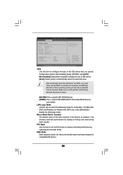
.../Large Mode Block (Multi-Sector Transfer) PIO Mode DMA Mode S.M.A.R.T. 32Bit Data Transfer [Auto] [Auto] [Auto] [Auto] [Auto] [Disabled] [Disabled] Select the type of device connected to automatically detect the hard disk drive. DMA Mode DMA capability allows the improved transfer-speed and data-integrity for IDE CD/DVD drives. [ARMD...
.../Large Mode Block (Multi-Sector Transfer) PIO Mode DMA Mode S.M.A.R.T. 32Bit Data Transfer [Auto] [Auto] [Auto] [Auto] [Auto] [Disabled] [Disabled] Select the type of device connected to automatically detect the hard disk drive. DMA Mode DMA capability allows the improved transfer-speed and data-integrity for IDE CD/DVD drives. [ARMD...
User Manual
Page 57
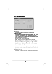
... system. USB Controller Use this item to enable or disable the use only under legacy OS and BIOS setup when [Disabled] is selected. There are connected. [Disabled] - Enables legacy support if USB devices are four configuration options: [Enabled], [Auto], [Disabled] and [BIOS Setup Only]. If you have USB compatibility issue, it...
... system. USB Controller Use this item to enable or disable the use only under legacy OS and BIOS setup when [Disabled] is selected. There are connected. [Disabled] - Enables legacy support if USB devices are four configuration options: [Enabled], [Auto], [Disabled] and [BIOS Setup Only]. If you have USB compatibility issue, it...

