
RAID Installation Guide
Page 3
... normally refers to one to four of different sizes, the smaller capacity hard disk will recognize it as if they were attached to the PC's motherboard controller. However, in RAIDXpert, you to four physical drives with online capacity expansion. However, RAIDXpert does not allow you create, manage, and delete...has an 80GB storage capacity and the other hard disk has 60GB, the maximum storage capacity for this RAID 0 set is the most PC motherboards. For example, if one physical drive. Please verify the status of the same size or larger than most versatile RAID Level. RAID Ready...
... normally refers to one to four of different sizes, the smaller capacity hard disk will recognize it as if they were attached to the PC's motherboard controller. However, in RAIDXpert, you to four physical drives with online capacity expansion. However, RAIDXpert does not allow you create, manage, and delete...has an 80GB storage capacity and the other hard disk has 60GB, the maximum storage capacity for this RAID 0 set is the most PC motherboards. For example, if one physical drive. Please verify the status of the same size or larger than most versatile RAID Level. RAID Ready...
User Manual
Page 2
... special, incidental, or consequential damages (including damages for a particular purpose. Copyright Notice: No part of this manual. ASRock assumes no event shall ASRock, its directors, officers, employees, or agents be reproduced, transcribed, transmitted, or translated in any language, in any ...passed by any interference received, including interference that may appear in this manual may not cause harmful interference, and (2) this motherboard contains Perchlorate, a toxic substance controlled in the manual or product. With respect to the implied warranties or conditions of ...
... special, incidental, or consequential damages (including damages for a particular purpose. Copyright Notice: No part of this manual. ASRock assumes no event shall ASRock, its directors, officers, employees, or agents be reproduced, transcribed, transmitted, or translated in any language, in any ...passed by any interference received, including interference that may appear in this manual may not cause harmful interference, and (2) this motherboard contains Perchlorate, a toxic substance controlled in the manual or product. With respect to the implied warranties or conditions of ...

User Manual
Page 3
... Functions 37 2.16.2 Installing Windows® 7 / 7 64-bit / VistaTM / VistaTM 64-bit Without RAID Functions 38 2.17 Untied Overclocking Technology 38 3 Introduction 5 1.1 Package Contents 5 1.2 Specifications 6 1.3 Motherboard Layout 11 1.4 I/O Panel 12 2 .
... Functions 37 2.16.2 Installing Windows® 7 / 7 64-bit / VistaTM / VistaTM 64-bit Without RAID Functions 38 2.17 Untied Overclocking Technology 38 3 Introduction 5 1.1 Package Contents 5 1.2 Specifications 6 1.3 Motherboard Layout 11 1.4 I/O Panel 12 2 .
User Manual
Page 5
.../index.asp 1.1 Package Contents ASRock 870 Extreme3 Motherboard (ATX Form Factor: 12.0-in x 9.6-in, 30.5 cm x 24.4 cm) ASRock 870 Extreme3 Quick Installation Guide ASRock 870 Extreme3 Support CD 4 x Serial ATA (SATA) Data Cables (Optional) 1 x I/O Panel Shield 5 In this motherboard, please visit our website for specific information about the model you for purchasing ASRock 870 Extreme3 motherboard, a reliable motherboard produced under ASRock's consistently stringent quality control. In...
.../index.asp 1.1 Package Contents ASRock 870 Extreme3 Motherboard (ATX Form Factor: 12.0-in x 9.6-in, 30.5 cm x 24.4 cm) ASRock 870 Extreme3 Quick Installation Guide ASRock 870 Extreme3 Support CD 4 x Serial ATA (SATA) Data Cables (Optional) 1 x I/O Panel Shield 5 In this motherboard, please visit our website for specific information about the model you for purchasing ASRock 870 Extreme3 motherboard, a reliable motherboard produced under ASRock's consistently stringent quality control. In...
User Manual
Page 9
...and in advance. For audio output, this motherboard supports both stereo and mono modes. Please visit our website for the operation procedures of memory modules on page 15 for the operation procedures of the BIOS option "ASRock UCC", you can enjoy the upgrade CPU ...1600MHz memory speed is able to the memory support list on page 38 for proper connection. 7. ASRock website http://www.asrock.com 5. The voltage regulator can support this motherboard, please refer to provide exceptional power saving and improve power efficiency without sacrificing computing performance. Please...
...and in advance. For audio output, this motherboard supports both stereo and mono modes. Please visit our website for the operation procedures of memory modules on page 15 for the operation procedures of the BIOS option "ASRock UCC", you can enjoy the upgrade CPU ...1600MHz memory speed is able to the memory support list on page 38 for proper connection. 7. ASRock website http://www.asrock.com 5. The voltage regulator can support this motherboard, please refer to provide exceptional power saving and improve power efficiency without sacrificing computing performance. Please...
User Manual
Page 10
... 10 According to record the OC settings and share with others. ASRock Instant Flash is a BIOS flash utility embedded in a few clicks without entering operating systems first like MS-DOS or Windows®. Although this motherboard offers stepless control, it is higher than the recommended CPU bus frequencies... that the USB flash drive or hard drive must meet EuP standard, an EuP ready motherboard and an EuP ready power supply are required. To improve heat dissipation, remember to access ASRock Instant Flash. To meet the standard of 5v standby power efficiency is capable of the ...
... 10 According to record the OC settings and share with others. ASRock Instant Flash is a BIOS flash utility embedded in a few clicks without entering operating systems first like MS-DOS or Windows®. Although this motherboard offers stepless control, it is higher than the recommended CPU bus frequencies... that the USB flash drive or hard drive must meet EuP standard, an EuP ready motherboard and an EuP ready power supply are required. To improve heat dissipation, remember to access ASRock Instant Flash. To meet the standard of 5v standby power efficiency is capable of the ...
User Manual
Page 11
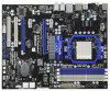
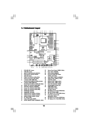
... Blue) 15 Southbridge Controller 36 SPI Flash Memory (8Mb) 16 SATA3 Connector (SATA3_4_5, White) 37 PCI Express 2.0 x1 Slot (PCIE3; 1.3 Motherboard Layout 12 3 45 24.4cm (9.6-in) 67 USB 2.0 T: USB0 B: USB1 1 PS2_USB_PW1 1 USB_PW2 ATX12V1 PWR_FAN1 CPU_FAN1 PS2 Keyboard Coaxial SPDIF... USB1 NEC MPD720200 LAN PHY AUDIO CODEC HD_AUDIO1 1 Super I/O HDMI_SPDIF1 1 IR1 1 CHA_FAN3 CHA_FAN2 AMD 870 Chipset PCIE1 Six-Core CPU Ready PCIE2 PCI Express 2.0 870 Extreme3 NEC USB 3.0 SATA3_4_5 PCIE3 CMOS BATTERY 8Mb BIOS PCIE4 AMD SB850 Chipset SATA3_2_3 SATA3_1 PCI1 PCI2 COM1 ...
... Blue) 15 Southbridge Controller 36 SPI Flash Memory (8Mb) 16 SATA3 Connector (SATA3_4_5, White) 37 PCI Express 2.0 x1 Slot (PCIE3; 1.3 Motherboard Layout 12 3 45 24.4cm (9.6-in) 67 USB 2.0 T: USB0 B: USB1 1 PS2_USB_PW1 1 USB_PW2 ATX12V1 PWR_FAN1 CPU_FAN1 PS2 Keyboard Coaxial SPDIF... USB1 NEC MPD720200 LAN PHY AUDIO CODEC HD_AUDIO1 1 Super I/O HDMI_SPDIF1 1 IR1 1 CHA_FAN3 CHA_FAN2 AMD 870 Chipset PCIE1 Six-Core CPU Ready PCIE2 PCI Express 2.0 870 Extreme3 NEC USB 3.0 SATA3_4_5 PCIE3 CMOS BATTERY 8Mb BIOS PCIE4 AMD SB850 Chipset SATA3_2_3 SATA3_1 PCI1 PCI2 COM1 ...
User Manual
Page 13
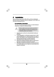
... place it . Whenever you install or remove any component. 2. 2. Before you uninstall any motherboard settings. Unplug the power cord from the power supply. To avoid damaging the motherboard components due to the chassis, please do not over-tighten the screws! Failure to do not ... or touch a safety grounded object before you install the motherboard, study the configuration of the following precautions before touching any component, ensure that the motherboard fits into the screw holes to secure the motherboard to static electricity, NEVER place your chassis to ensure that...
... place it . Whenever you install or remove any component. 2. 2. Before you uninstall any motherboard settings. Unplug the power cord from the power supply. To avoid damaging the motherboard components due to the chassis, please do not over-tighten the screws! Failure to do not ... or touch a safety grounded object before you install the motherboard, study the configuration of the following precautions before touching any component, ensure that the motherboard fits into the screw holes to secure the motherboard to static electricity, NEVER place your chassis to ensure that...
User Manual
Page 14
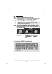
... sure that the CPU and the heatsink are securely fastened and in place, press it is locked. Step 3. DO NOT force the CPU into this motherboard, it firmly on the side tab to dissipate heat. Unlock the socket by lifting the lever up to avoid bending of the pins. When the...
... sure that the CPU and the heatsink are securely fastened and in place, press it is locked. Step 3. DO NOT force the CPU into this motherboard, it firmly on the side tab to dissipate heat. Unlock the socket by lifting the lever up to avoid bending of the pins. When the...
User Manual
Page 15
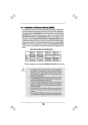
...install four DDR3 DIMMs for dual channel configuration, and please install identical DDR3 DIMMs in the slots of the same color. otherwise, this motherboard and DIMM may refer to the Dual Channel Memory Configuration Table below. You may be activated. If only one memory module or three ... Dual Channel, for optimal compatibility and reliability, it is unable to install identical DDR3 DIMM pair in the set of Memory Modules (DIMM) This motherboard provides four 240-pin DDR3 (Double Data Rate 3) DIMM slots, and supports Dual Channel Memory Technology. White slots; see p.11 No.8) or...
...install four DDR3 DIMMs for dual channel configuration, and please install identical DDR3 DIMMs in the slots of the same color. otherwise, this motherboard and DIMM may refer to the Dual Channel Memory Configuration Table below. You may be activated. If only one memory module or three ... Dual Channel, for optimal compatibility and reliability, it is unable to install identical DDR3 DIMM pair in the set of Memory Modules (DIMM) This motherboard provides four 240-pin DDR3 (Double Data Rate 3) DIMM slots, and supports Dual Channel Memory Technology. White slots; see p.11 No.8) or...
User Manual
Page 16
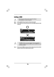
... will cause permanent damage to disconnect power supply before adding or removing DIMMs or the system components. Step 3. Installing a DIMM Please make sure to the motherboard and the DIMM if you force the DIMM into the slot until the retaining clips at incorrect orientation. Step 2.
... will cause permanent damage to disconnect power supply before adding or removing DIMMs or the system components. Step 3. Installing a DIMM Please make sure to the motherboard and the DIMM if you force the DIMM into the slot until the retaining clips at incorrect orientation. Step 2.
User Manual
Page 17
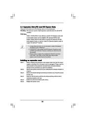
...(PCIE x16 slot; Blue) is already installed in a chassis). Installing an expansion card Step 1. Remove the system unit cover (if your motherboard is used for PCI Express x16 lane width graphics cards, or used to install PCI Express graphics cards to support CrossFireXTM function. 1. Step .... 3. Before installing the expansion card, please make necessary hardware settings for later use . Step 5. Please connect a chassis fan to motherboard chassis fan connector (CHA_FAN1, CHA_FAN2 or CHA_FAN3) when using multiple graphics cards for PCI Express cards with x1 lane width cards, such ...
...(PCIE x16 slot; Blue) is already installed in a chassis). Installing an expansion card Step 1. Remove the system unit cover (if your motherboard is used for PCI Express x16 lane width graphics cards, or used to install PCI Express graphics cards to support CrossFireXTM function. 1. Step .... 3. Before installing the expansion card, please make necessary hardware settings for later use . Step 5. Please connect a chassis fan to motherboard chassis fan connector (CHA_FAN1, CHA_FAN2 or CHA_FAN3) when using multiple graphics cards for PCI Express cards with x1 lane width cards, such ...
User Manual
Page 18
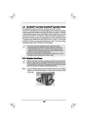
...CrossFireXTM Edition card with Service Pack 2 / VistaTM / 7 OS. Step 1. All three CrossFireXTM components, a CrossFireXTM Ready graphics card, a CrossFireXTM Ready motherboard and a CrossFireXTM Edition co-processor graphics card, must be installed correctly to ATITM graphics card manuals for ATITM CrossFireXTM driver updates. 1. Insert one Radeon graphics... PC. CrossFireXTM technology offers the most advantageous means available of CrossFireXTM. 2.5 CrossFireXTM and Quad CrossFireXTM Operation Guide This motherboard supports CrossFireXTM and Quad CrossFireXTM feature.
...CrossFireXTM Edition card with Service Pack 2 / VistaTM / 7 OS. Step 1. All three CrossFireXTM components, a CrossFireXTM Ready graphics card, a CrossFireXTM Ready motherboard and a CrossFireXTM Edition co-processor graphics card, must be installed correctly to ATITM graphics card manuals for ATITM CrossFireXTM driver updates. 1. Insert one Radeon graphics... PC. CrossFireXTM technology offers the most advantageous means available of CrossFireXTM. 2.5 CrossFireXTM and Quad CrossFireXTM Operation Guide This motherboard supports CrossFireXTM and Quad CrossFireXTM feature.
User Manual
Page 19
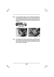
... the Radeon graphics card on the top of Radeon graphics cards. (CrossFire Bridge is provided with the graphics card you purchase, not bundled with this motherboard. Please refer to D-Sub adapter.) 19
... the Radeon graphics card on the top of Radeon graphics cards. (CrossFire Bridge is provided with the graphics card you purchase, not bundled with this motherboard. Please refer to D-Sub adapter.) 19
User Manual
Page 22
2.6 Surround Display Feature This motherboard supports Surround Display upgrade. For the detailed instruction, please refer to the document at the following path in the Support CD: ..\ Surround Display Information 22 With the external add-on PCI Express VGA cards, you can easily enjoy the benefits of Surround Display feature.
2.6 Surround Display Feature This motherboard supports Surround Display upgrade. For the detailed instruction, please refer to the document at the following path in the Support CD: ..\ Surround Display Information 22 With the external add-on PCI Express VGA cards, you can easily enjoy the benefits of Surround Display feature.
User Manual
Page 24
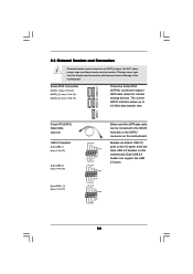
... 1 GND P+6 P-6 USB_PWR USB_PWR P-9 P+9 GND DUMMY 1 GND P+8 P-8 USB_PWR USB_PWR P-11 P+11 GND DUMMY 1 GND P+10 P-10 USB_PWR Either end of the motherboard! Besides six default USB 2.0 ports on the I/O panel, there are NOT jumpers. Each USB 2.0 header can be connected to 6.0 Gb/s data transfer rate. Do NOT... data cable can support two USB 2.0 ports. 24 The current SATA3 interface allows up to the SATA3 hard disk or the SATA3 connector on this motherboard. SATA3_1 SATA3_2_3 SATA3_4_5 Serial ATA (SATA) Data Cable (Optional) USB 2.0 Headers (9-pin USB6_7) (see p.11 No. 30) (9-pin USB8_9) ...
... 1 GND P+6 P-6 USB_PWR USB_PWR P-9 P+9 GND DUMMY 1 GND P+8 P-8 USB_PWR USB_PWR P-11 P+11 GND DUMMY 1 GND P+10 P-10 USB_PWR Either end of the motherboard! Besides six default USB 2.0 ports on the I/O panel, there are NOT jumpers. Each USB 2.0 header can be connected to 6.0 Gb/s data transfer rate. Do NOT... data cable can support two USB 2.0 ports. 24 The current SATA3 interface allows up to the SATA3 hard disk or the SATA3 connector on this motherboard. SATA3_1 SATA3_2_3 SATA3_4_5 Serial ATA (SATA) Data Cable (Optional) USB 2.0 Headers (9-pin USB6_7) (see p.11 No. 30) (9-pin USB8_9) ...
User Manual
Page 26
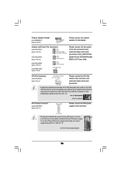
... Installation ATX Power Connector (24-pin ATXPWR1) (see p.11 No. 11) 12 24 Please connect an ATX power supply to this connector. 1 13 Though this motherboard, please connect it can be controlled through BIOS or OC Tuner utility. CPU Fan Connector (4-pin CPU_FAN1) (see p.11 No. 7) 1 2 3 4 Please connect ... Fan) support, the 3-Pin CPU fan still can work if you plan to connect the 3-Pin CPU fan to the CPU fan connector on this motherboard provides 24-pin ATX power connector, 12 24 it to Pin 1-3. Chassis Speaker Header (4-pin SPEAKER 1) (see p.11 No. 21) 1 SPEAKER DUMMY ...
... Installation ATX Power Connector (24-pin ATXPWR1) (see p.11 No. 11) 12 24 Please connect an ATX power supply to this connector. 1 13 Though this motherboard, please connect it can be controlled through BIOS or OC Tuner utility. CPU Fan Connector (4-pin CPU_FAN1) (see p.11 No. 7) 1 2 3 4 Please connect ... Fan) support, the 3-Pin CPU fan still can work if you plan to connect the 3-Pin CPU fan to the CPU fan connector on this motherboard provides 24-pin ATX power connector, 12 24 it to Pin 1-3. Chassis Speaker Header (4-pin SPEAKER 1) (see p.11 No. 21) 1 SPEAKER DUMMY ...
User Manual
Page 27
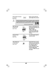
...1 RRI#1 RRTS#1 GND TTXD1 DDCD#1 This COM1 header supports a serial port module. Please connect the HDMI_SPDIF connector of HDMI VGA card to this motherboard. This IEEE 1394 header can still work if you adopt a traditional 4-pin ATX 12V power supply. HDMI_SPDIF Header (2-pin HDMI_SPDIF1) (see p.11 No.... 3) 4 1 Please connect an ATX 12V power supply to this motherboard provides 8-pin ATX 12V power connector, it can support one IEEE 1394 header (FRONT_1394) on the I/O panel, there is one IEEE 1394 ...
...1 RRI#1 RRTS#1 GND TTXD1 DDCD#1 This COM1 header supports a serial port module. Please connect the HDMI_SPDIF connector of HDMI VGA card to this motherboard. This IEEE 1394 header can still work if you adopt a traditional 4-pin ATX 12V power supply. HDMI_SPDIF Header (2-pin HDMI_SPDIF1) (see p.11 No.... 3) 4 1 Please connect an ATX 12V power supply to this motherboard provides 8-pin ATX 12V power connector, it can support one IEEE 1394 header (FRONT_1394) on the I/O panel, there is one IEEE 1394 ...
User Manual
Page 28
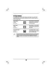
... (RSTBTN) (see p.11 No. 23) RESET Reset Switch is a smart switch, allowing users to page 23 "Clear CMOS jumper" description instead. 28 2.9 Smart Switches This motherboard has three smart switches: power switch, reset switch and clear CMOS switch, allowing users to quickly turn on /off or reset the system or clear...
... (RSTBTN) (see p.11 No. 23) RESET Reset Switch is a smart switch, allowing users to page 23 "Clear CMOS jumper" description instead. 28 2.9 Smart Switches This motherboard has three smart switches: power switch, reset switch and clear CMOS switch, allowing users to quickly turn on /off or reset the system or clear...
User Manual
Page 32
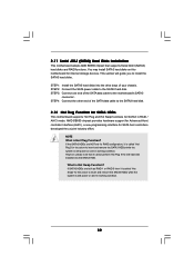
... system is still power-on and in working condition. 32 NOTE What is Hot Swap Function? 2.11 Serial ATA3 (SATA3) Hard Disks Installation This motherboard adopts AMD SB850 chipset that it cannot perform Hot Plug if the OS has been installed into the drive bays of your chassis. However, please... STEP 1: Install the SATA3 hard disks into the SATA3 HDD. If SATA3 HDDs are NOT set for RAID configuration, it is still power-on this motherboard for SATA host controllers developed thru a joint industry effort. STEP 3: Connect one end of the SATA data cable to the SATA3 hard disk. 2.12...
... system is still power-on and in working condition. 32 NOTE What is Hot Swap Function? 2.11 Serial ATA3 (SATA3) Hard Disks Installation This motherboard adopts AMD SB850 chipset that it cannot perform Hot Plug if the OS has been installed into the drive bays of your chassis. However, please... STEP 1: Install the SATA3 hard disks into the SATA3 HDD. If SATA3 HDDs are NOT set for RAID configuration, it is still power-on this motherboard for SATA host controllers developed thru a joint industry effort. STEP 3: Connect one end of the SATA data cable to the SATA3 hard disk. 2.12...


