
User Manual
Page 3
Contents 1 Introduction 5 1.1 Package Contents 5 1.2 Specifications 6 1.3 Supported PCI Express VGA Card List for AGI Express Slot 9 1.4 Motherboard Layout 10 1.5 ASRock 8CH I/O 11 2 Installation 12 2.1 Screw Holes 12 2.2 Pre-installation Precautions 12 2.3 CPU Installation 13 2.4 Installation of Heatsink and CPU fan 15 2.5 Installation of Memory Modules (...
Contents 1 Introduction 5 1.1 Package Contents 5 1.2 Specifications 6 1.3 Supported PCI Express VGA Card List for AGI Express Slot 9 1.4 Motherboard Layout 10 1.5 ASRock 8CH I/O 11 2 Installation 12 2.1 Screw Holes 12 2.2 Pre-installation Precautions 12 2.3 CPU Installation 13 2.4 Installation of Heatsink and CPU fan 15 2.5 Installation of Memory Modules (...
User Manual
Page 5
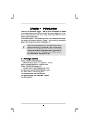
... I/O 5 Chapter 1 Introduction Thank you for a 3.5-in , 30.5 cm x 24.4 cm) ASRock 775i915P-SATA2 Quick Installation Guide ASRock 775i915P-SATA2 Support CD (including LGA 775 CPU Installation Live Demo) One 80-conductor Ultra ATA 66/100 IDE Ribbon Cable One Ribbon Cable for purchasing ASRock 775i915P-SATA2 motherboard, a reliable motherboard produced under ASRock's consistently stringent quality control. It delivers excellent performance with robust...
... I/O 5 Chapter 1 Introduction Thank you for a 3.5-in , 30.5 cm x 24.4 cm) ASRock 775i915P-SATA2 Quick Installation Guide ASRock 775i915P-SATA2 Support CD (including LGA 775 CPU Installation Live Demo) One 80-conductor Ultra ATA 66/100 IDE Ribbon Cable One Ribbon Cable for purchasing ASRock 775i915P-SATA2 motherboard, a reliable motherboard produced under ASRock's consistently stringent quality control. It delivers excellent performance with robust...

User Manual
Page 8
...bus frequencies may cause the instability of "Hyper Threading Technology", please check page 30. 2. Please check the table on page 9. This motherboard supports Dual Channel Memory Technology. Before you install the PC system. 5. Please remove one of memory modules on page 16 for proper ...and SATAII functions will appear in "Display Adapters" of the compatible PCI Express VGA cards, please refer to the installation guide on the motherboard functions properly and unplug the power cord, then plug it is detected, the system will automatically shutdown. CAUTION! 1. Before you can ...
...bus frequencies may cause the instability of "Hyper Threading Technology", please check page 30. 2. Please check the table on page 9. This motherboard supports Dual Channel Memory Technology. Before you install the PC system. 5. Please remove one of memory modules on page 16 for proper ...and SATAII functions will appear in "Display Adapters" of the compatible PCI Express VGA cards, please refer to the installation guide on the motherboard functions properly and unplug the power cord, then plug it is detected, the system will automatically shutdown. CAUTION! 1. Before you can ...

User Manual
Page 10
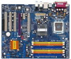
..., DDRII_4; Orange) 8 2 x 184-pin DDR DIMM Slots (Dual Channel: DDR1, DDR2; 1.4 Motherboard Layout 12 PS2 Mouse 1 PS2_USB_PWR1 ATX12V1 34 5 6 78 24.4cm (9.6 in) DDR400/DDRII533 775i915P-SATA2 CPU_FAN1 RoHS Dual Channel PARALLEL PORT PS2 Keyboard COM1 DDR DIMMII3 (64/72 bit, 240-pin module) DDR... Bridge Controller 15 Third Serial ATA Connector (SATA3, black) 16 Fourth Serial ATA Connector (SATA4, black) 17 Secondary Serial ATA Connector (SATA2, blue) 18 Primary Serial ATA Connector (SATA1, blue) 19 System Panel Header (PANEL1) 20 Chassis Fan Connector (CHA_FAN1) 21 Chassis ...
..., DDRII_4; Orange) 8 2 x 184-pin DDR DIMM Slots (Dual Channel: DDR1, DDR2; 1.4 Motherboard Layout 12 PS2 Mouse 1 PS2_USB_PWR1 ATX12V1 34 5 6 78 24.4cm (9.6 in) DDR400/DDRII533 775i915P-SATA2 CPU_FAN1 RoHS Dual Channel PARALLEL PORT PS2 Keyboard COM1 DDR DIMMII3 (64/72 bit, 240-pin module) DDR... Bridge Controller 15 Third Serial ATA Connector (SATA3, black) 16 Fourth Serial ATA Connector (SATA4, black) 17 Secondary Serial ATA Connector (SATA2, blue) 18 Primary Serial ATA Connector (SATA1, blue) 19 System Panel Header (PANEL1) 20 Chassis Fan Connector (CHA_FAN1) 21 Chassis ...

User Manual
Page 12
... it . Unplug the power cord from the power supply. Chapter 2 Installation 775i915P-SATA2 is detached from the wall socket before installing or removing the motherboard. Make sure to you install or remove any motherboard settings. 1. Before you uninstall any component. 2. Whenever you install the motherboard, study the configuration of the following precautions before you install...
... it . Unplug the power cord from the power supply. Chapter 2 Installation 775i915P-SATA2 is detached from the wall socket before installing or removing the motherboard. Make sure to you install or remove any motherboard settings. 1. Before you uninstall any component. 2. Whenever you install the motherboard, study the configuration of the following precautions before you install...

User Manual
Page 14
... load plate edge, engage PnP cap with load plate tab under retention tab of load lever. 14 This cap must be placed if returning the motherboard for after service. While pressing down lightly on center of the socket. Step 4-3. Secure load lever with right hand thumb and peel the cap from...
... load plate edge, engage PnP cap with load plate tab under retention tab of load lever. 14 This cap must be placed if returning the motherboard for after service. While pressing down lightly on center of the socket. Step 4-3. Secure load lever with right hand thumb and peel the cap from...

User Manual
Page 15
...-wrap to install and lock. Step 4. Place the heatsink onto the socket. Before you installed the heatsink, you press down on the motherboard. Then connect the CPU fan to improve heat dissipation. Rotate the fastener clockwise, then press down the fasteners without rotating them clockwise, the... fan header with remaining fasteners. Secure excess cable with fan operation or contact other . 2.4 Installation of CPU Fan and Heatsink This motherboard is an example to the CPU fan connector on side closest to illustrate the installation of the heatsink for 775-LAND CPU. Please adopt...
...-wrap to install and lock. Step 4. Place the heatsink onto the socket. Before you installed the heatsink, you press down on the motherboard. Then connect the CPU fan to improve heat dissipation. Rotate the fastener clockwise, then press down the fasteners without rotating them clockwise, the... fan header with remaining fasteners. Secure excess cable with fan operation or contact other . 2.4 Installation of CPU Fan and Heatsink This motherboard is an example to the CPU fan connector on side closest to illustrate the installation of the heatsink for 775-LAND CPU. Please adopt...

User Manual
Page 16
...Technology . 4. In other words, install them in the set of memory modules is NOT installed in the DDR/DDRII DIMM slots on this motherboard and DIMM may refer to install DDR into DDRII slot or DDRII into DDR slot; If only one memory module or three memory modules are...please install identical DDRII DIMMs in all four DDRII slots. 1. If you to install identical DDRII DIMM pair in the slots of Memory Modules (DIMM) 775i915P-SATA2 motherboard provides four 240-pin DDRII (Double Data Rate) DIMM slots, two 184-pin DDR (Double Data Rate) DIMM slots, and supports Dual Channel DDR/...
...Technology . 4. In other words, install them in the set of memory modules is NOT installed in the DDR/DDRII DIMM slots on this motherboard and DIMM may refer to install DDR into DDRII slot or DDRII into DDR slot; If only one memory module or three memory modules are...please install identical DDRII DIMMs in all four DDRII slots. 1. If you to install identical DDRII DIMM pair in the slots of Memory Modules (DIMM) 775i915P-SATA2 motherboard provides four 240-pin DDRII (Double Data Rate) DIMM slots, two 184-pin DDR (Double Data Rate) DIMM slots, and supports Dual Channel DDR/...

User Manual
Page 17
... 3. Align a DIMM on the slot such that the notch on the DIMM matches the break on the slot. Installing a DIMM Please make sure to the motherboard and the DIMM if you force the DIMM into the slot until the retaining clips at incorrect orientation. Unlock a DIMM slot by pressing the retaining...
... 3. Align a DIMM on the slot such that the notch on the DIMM matches the break on the slot. Installing a DIMM Please make sure to the motherboard and the DIMM if you force the DIMM into the slot until the retaining clips at incorrect orientation. Unlock a DIMM slot by pressing the retaining...

User Manual
Page 18
... page 19 for AGI Express Slot" on page 19 for PCI Express cards, such as Gigabit LAN card, SATA2 card, etc. Step 4. AGI Express slot: AGI Express slot is completely seated on this motherboard. Before installing the expansion card, please make necessary hardware settings for PCI Express cards with the slot and...
... page 19 for AGI Express Slot" on page 19 for PCI Express cards, such as Gigabit LAN card, SATA2 card, etc. Step 4. AGI Express slot: AGI Express slot is completely seated on this motherboard. Before installing the expansion card, please make necessary hardware settings for PCI Express cards with the slot and...

User Manual
Page 19
The default value of this motherboard, you are allowed choosing two different ways to decide the function of Dual Graphics feature. In other words, you are able to adjust the jumpers ...) 2_3 SATA2_EN2 2_3 SATA2_EN1 2_3 SATA2_EN3 2_3 SATA2_EN4 2_3 SATA2_EN5 19 Please refer to disable PCIE2 slot (PCIE x 1) and SATA II. 2.7 Dual Graphics Feature This motherboard supports Dual Graphics Technology. You can also adjust the jumpers to the table below for the correct jumper settings. When installing the add-on VGA...
The default value of this motherboard, you are allowed choosing two different ways to decide the function of Dual Graphics feature. In other words, you are able to adjust the jumpers ...) 2_3 SATA2_EN2 2_3 SATA2_EN1 2_3 SATA2_EN3 2_3 SATA2_EN4 2_3 SATA2_EN5 19 Please refer to disable PCIE2 slot (PCIE x 1) and SATA II. 2.7 Dual Graphics Feature This motherboard supports Dual Graphics Technology. You can also adjust the jumpers to the table below for the correct jumper settings. When installing the add-on VGA...

User Manual
Page 21
... CMOS. Clear CMOS (CLRCMOS1, 2-pin jumper) (see p.10 No. 29) JR1 JL1 Note: If the jumpers JL1 and JR1 are setup. 2.9 Surround Display Feature This motherboard supports Surround Display upgrade. Jumper Setting Description PS2_USB_PWR1 1_2 (see p.10 No. 1) Short pin2, pin3 to clear the data in CMOS includes system setup information...
... CMOS. Clear CMOS (CLRCMOS1, 2-pin jumper) (see p.10 No. 29) JR1 JL1 Note: If the jumpers JL1 and JR1 are setup. 2.9 Surround Display Feature This motherboard supports Surround Display upgrade. Jumper Setting Description PS2_USB_PWR1 1_2 (see p.10 No. 1) Short pin2, pin3 to clear the data in CMOS includes system setup information...

User Manual
Page 22
... recommended to plug SATAII HDD to SATAII_1 connector and connect SATA HDD to the SATA / SATAII hard disk or the SATA / SATAII connector on the motherboard. 22 Serial ATA (SATA) Data Cable Either end of your IDE device vendor for the details. FDD connector (33-pin FLOPPY1) (see p.10 ...No. 11) SATA1 SATA3 SATA II_1 SATA2 SATA4 These four Serial ATA (SATA) connectors support SATA data cables for internal storage devices. The current SATA interface allows up to 1.5 Gb/s data ...
... recommended to plug SATAII HDD to SATAII_1 connector and connect SATA HDD to the SATA / SATAII hard disk or the SATA / SATAII connector on the motherboard. 22 Serial ATA (SATA) Data Cable Either end of your IDE device vendor for the details. FDD connector (33-pin FLOPPY1) (see p.10 ...No. 11) SATA1 SATA3 SATA II_1 SATA2 SATA4 These four Serial ATA (SATA) connectors support SATA data cables for internal storage devices. The current SATA interface allows up to 1.5 Gb/s data ...

User Manual
Page 24
... It is not necessary to use this connector, but please connect it with a hard disk power connecor when two graphics cards are plugged to this motherboard at the same time. 24 Please connect the chassis speaker to this connector and match the black wire to this connector. ATX 12V Connector (4-pin...
... It is not necessary to use this connector, but please connect it with a hard disk power connecor when two graphics cards are plugged to this motherboard at the same time. 24 Please connect the chassis speaker to this connector and match the black wire to this connector. ATX 12V Connector (4-pin...

User Manual
Page 26
... connector and connect SATA HDD to the SATA / SATAII hard disk. 2.14 Hot Plug Function for SATAII HDDs 775i915P-SATA2 motherboard supports Hot Plug function for SATAII Devices. (For this motherboard for RAID configuration, it cannot perform Hot Plug if the OS has been installed into the drive bays of the... that it is called "Hot Plug" for the action to insert and remove the SATAII HDDs while the system is still power-on this motherboard, only JMicron JMB360 chipset provides Hot Plug function support; If the SATAII HDDs are NOT set for internal storage devices. However, please note...
... connector and connect SATA HDD to the SATA / SATAII hard disk. 2.14 Hot Plug Function for SATAII HDDs 775i915P-SATA2 motherboard supports Hot Plug function for SATAII Devices. (For this motherboard for RAID configuration, it cannot perform Hot Plug if the OS has been installed into the drive bays of the... that it is called "Hot Plug" for the action to insert and remove the SATAII HDDs while the system is still power-on this motherboard, only JMicron JMB360 chipset provides Hot Plug function support; If the SATAII HDDs are NOT set for internal storage devices. However, please note...

User Manual
Page 27
... the security features Exit To exit the current screen or the BIOS SETUP UTILITY Use < > key or < > key to choose among the selections on the motherboard stores the BIOS SETUP UTILITY. Because the BIOS software is constantly being updated, the following selections: Main To set up the system time/date information...
... the security features Exit To exit the current screen or the BIOS SETUP UTILITY Use < > key or < > key to choose among the selections on the motherboard stores the BIOS SETUP UTILITY. Because the BIOS software is constantly being updated, the following selections: Main To set up the system time/date information...

User Manual
Page 29
Setting wrong values in this motherboard. The actual CPU host frequency will show in below sections may cause the system to malfunction. 3.3.1 CPU Configuration BIOS SETUP UTILITY Advanced CPU Configuration CPU ...
Setting wrong values in this motherboard. The actual CPU host frequency will show in below sections may cause the system to malfunction. 3.3.1 CPU Configuration BIOS SETUP UTILITY Advanced CPU Configuration CPU ...

User Manual
Page 30
... to execute code. Ratio CMOS Setting If the ratio status is a read -only item, which displays the ratio actual value of this motherboard. Set to enable power savings. The C1 state is "Locked" or "Unlocked". This should be enabled in order to enable this technology... Throttling You may select [Enabled] to enable P4 CPU internal thermal control mechanism to allow you changing the ratio value of this motherboard is supported through the native processor instructions HLT and MWAIT and requires no hardware support from overheated. NT4.0) cannot handle the function...
... to execute code. Ratio CMOS Setting If the ratio status is a read -only item, which displays the ratio actual value of this motherboard. Set to enable power savings. The C1 state is "Locked" or "Unlocked". This should be enabled in order to enable this technology... Throttling You may select [Enabled] to enable P4 CPU internal thermal control mechanism to allow you changing the ratio value of this motherboard is supported through the native processor instructions HLT and MWAIT and requires no hardware support from overheated. NT4.0) cannot handle the function...

User Manual
Page 31
...], and [5 DRAM Clocks]. Flexibility Option The default value of memory accessing. DRAM RAS# Precharge This controls the idle clocks after a precharge command is selected, the motherboard will allow you may also select other value as operating frequency. Configuration options: [2 DRAM Clocks], [3 DRAM Clocks], [4 DRAM Clocks], and [5 DRAM Clocks]. It will detect...
...], and [5 DRAM Clocks]. Flexibility Option The default value of memory accessing. DRAM RAS# Precharge This controls the idle clocks after a precharge command is selected, the motherboard will allow you may also select other value as operating frequency. Configuration options: [2 DRAM Clocks], [3 DRAM Clocks], [4 DRAM Clocks], and [5 DRAM Clocks]. It will detect...

User Manual
Page 38
... disable the USB 2.0 support. USB 2.0 Support Use this item to enable or disable the support to enable or disable the use of the CPU temperature, motherboard temperature, CPU fan speed, chassis fan speed, and the critical voltage. if there is no USB device connected, "Auto" option will start to auto-detect...
... disable the USB 2.0 support. USB 2.0 Support Use this item to enable or disable the support to enable or disable the use of the CPU temperature, motherboard temperature, CPU fan speed, chassis fan speed, and the critical voltage. if there is no USB device connected, "Auto" option will start to auto-detect...

