
User Manual
Page 3
... Graphics Feature 19 2.8 PCIE VGA Card Driver Installation Guide For Windows 98 SE / ME 20 2.9 Surround Display Feature 21 2.10 Jumpers Setup 21 2.11 Onboard Headers and Connectors 22 2.12 SATAII Hard Disk Setup Guide 25 2.13 Serial ATA (SATA) / Serial ATAII (SATAII) Hard Disks Installation 26 2.14 Hot Plug Function for SATAII HDDs 26 3 BIOS SETUP UTILITY 27 3.1 Introduction 27 3.1.1 BIOS Menu Bar 27 3.1.2 Navigation Keys 28 3.2 Main Screen 28 3.3 Advanced Screen 28 3.3.1 CPU Configuration 29 3.3.2 Chipset Configuration 30 3.3.3 ACPI Configuration 32 3.3.4 IDE Configuration...
... Graphics Feature 19 2.8 PCIE VGA Card Driver Installation Guide For Windows 98 SE / ME 20 2.9 Surround Display Feature 21 2.10 Jumpers Setup 21 2.11 Onboard Headers and Connectors 22 2.12 SATAII Hard Disk Setup Guide 25 2.13 Serial ATA (SATA) / Serial ATAII (SATAII) Hard Disks Installation 26 2.14 Hot Plug Function for SATAII HDDs 26 3 BIOS SETUP UTILITY 27 3.1 Introduction 27 3.1.1 BIOS Menu Bar 27 3.1.2 Navigation Keys 28 3.2 Main Screen 28 3.3 Advanced Screen 28 3.3.1 CPU Configuration 29 3.3.2 Chipset Configuration 30 3.3.3 ACPI Configuration 32 3.3.4 IDE Configuration...
User Manual
Page 5
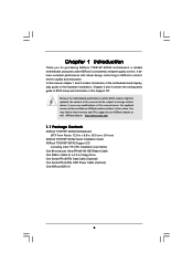
... configuration guide to the hardware installation. Because the motherboard specifications and the BIOS software might be updated, the content of this manual will be subject to quality and endurance. In case any modifications of this manual occur, the updated version will be available on ASRock website as well. ASRock website http://www.asrock.com 1.1 Package Contents ASRock 775i915P-SATA2 Motherboard (ATX Form Factor: 12.0-in x 9.6-in Floppy Drive One Serial ATA (SATA) Data Cable (Optional) One Serial ATA (SATA) HDD Power Cable (Optional...
... configuration guide to the hardware installation. Because the motherboard specifications and the BIOS software might be updated, the content of this manual will be subject to quality and endurance. In case any modifications of this manual occur, the updated version will be available on ASRock website as well. ASRock website http://www.asrock.com 1.1 Package Contents ASRock 775i915P-SATA2 Motherboard (ATX Form Factor: 12.0-in x 9.6-in Floppy Drive One Serial ATA (SATA) Data Cable (Optional) One Serial ATA (SATA) HDD Power Cable (Optional...

User Manual
Page 7
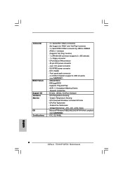
... Software - AMI Legal BIOS - Front panel audio connector - 2 x USB 2.0 headers (support 4 USB 2.0 ports) (see CAUTION 8) - CPU Overheat Shutdown to Protect CPU Life - Connector BIOS Feature Support CD Hardware Monitor OS Certifications - 4 x Serial ATA 1.5Gb/s connectors (No Support for "RAID" and "Hot Plug" functions) - 1 x Serial ATAII 3.0Gb/s connector by JMicron JMB360 (PCIE x 1 interface) (Supports "Hot Plug" function) - 1 x ATA100 IDE connector (supports 2 x IDE devices) - 1 x Floppy connector - CPU/Chassis FAN connector - 20 pin ATX power connector - 4 pin 12V power connector...
... Software - AMI Legal BIOS - Front panel audio connector - 2 x USB 2.0 headers (support 4 USB 2.0 ports) (see CAUTION 8) - CPU Overheat Shutdown to Protect CPU Life - Connector BIOS Feature Support CD Hardware Monitor OS Certifications - 4 x Serial ATA 1.5Gb/s connectors (No Support for "RAID" and "Hot Plug" functions) - 1 x Serial ATAII 3.0Gb/s connector by JMicron JMB360 (PCIE x 1 interface) (Supports "Hot Plug" function) - 1 x ATA100 IDE connector (supports 2 x IDE devices) - 1 x Floppy connector - CPU/Chassis FAN connector - 20 pin ATX power connector - 4 pin 12V power connector...

User Manual
Page 8
... to AGI Express slot, PCIE2 slot (PCIE x 1) and SATAII functions will be disabled. While CPU overheat is not recommended to the "Supported PCI Express VGA Card List for proper installation. 3. If you install PCI Express VGA card to spray thermal grease between the CPU and the heatsink when you can successfully install the VGA driver. 8 For audio output, this motherboard supports both stereo and mono modes. Power Management for proper connection. 7. Besides, after installing Windows 98 / ME, two display adapter controllers will automatically...
... to AGI Express slot, PCIE2 slot (PCIE x 1) and SATAII functions will be disabled. While CPU overheat is not recommended to the "Supported PCI Express VGA Card List for proper installation. 3. If you install PCI Express VGA card to spray thermal grease between the CPU and the heatsink when you can successfully install the VGA driver. 8 For audio output, this motherboard supports both stereo and mono modes. Power Management for proper connection. 7. Besides, after installing Windows 98 / ME, two display adapter controllers will automatically...

User Manual
Page 10
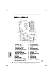
... Floppy Connector (FLOPPY1) 28 Game Port Header (GAME1) 29 JR1 JL1 Jumper 30 Front Panel Audio Header (AUDIO1) 31 PCI Slots (PCI1- 3) 32 PCIEX1_EN1 - 4 33 BIOS FWH Chip 34 PCI Express Slot (PCIE2) 35 PCI Express Slot (PCIE1) 36 SLI / XFIRE Power Connector 37 Internal Audio Connector: CD1 (Black) 38 ATX Power Connector (ATXPWR1) 10 1.4 Motherboard Layout 12 PS2 Mouse 1 PS2_USB_PWR1 ATX12V1 34 5 6 78 24.4cm (9.6 in) DDR400/DDRII533 775i915P-SATA2 CPU_FAN1 RoHS Dual Channel PARALLEL PORT PS2 Keyboard COM1 DDR DIMMII3 (64/72 bit, 240-pin...
... Floppy Connector (FLOPPY1) 28 Game Port Header (GAME1) 29 JR1 JL1 Jumper 30 Front Panel Audio Header (AUDIO1) 31 PCI Slots (PCI1- 3) 32 PCIEX1_EN1 - 4 33 BIOS FWH Chip 34 PCI Express Slot (PCIE2) 35 PCI Express Slot (PCIE1) 36 SLI / XFIRE Power Connector 37 Internal Audio Connector: CD1 (Black) 38 ATX Power Connector (ATXPWR1) 10 1.4 Motherboard Layout 12 PS2 Mouse 1 PS2_USB_PWR1 ATX12V1 34 5 6 78 24.4cm (9.6 in) DDR400/DDRII533 775i915P-SATA2 CPU_FAN1 RoHS Dual Channel PARALLEL PORT PS2 Keyboard COM1 DDR DIMMII3 (64/72 bit, 240-pin...

User Manual
Page 25
... remove the jumpers from pin 5 and pin 6. Please visit HITACHI's website for your reference. For different SATAII hard disk products of SATAII hard disk drives may not be enabled. Western Digital 7531 8642 If pin 5 and pin 6 are just for details: http://www.hitachigst.com/hdd/support/download.htm The above examples are shorted, SATA 1.5GB/s will be at SATAII mode. Please visit the vendors' website for changing various...
... remove the jumpers from pin 5 and pin 6. Please visit HITACHI's website for your reference. For different SATAII hard disk products of SATAII hard disk drives may not be enabled. Western Digital 7531 8642 If pin 5 and pin 6 are just for details: http://www.hitachigst.com/hdd/support/download.htm The above examples are shorted, SATA 1.5GB/s will be at SATAII mode. Please visit the vendors' website for changing various...

User Manual
Page 29
... (MHz) Boot Failure Guard Spread Spectrum [Auto] [200] [Enabled] [Auto] Select how to set the CPU host frequency. CPU Host Frequency While entering setup, BIOS auto detects the present CPU host frequency of Boot Failure Guard. CPU Configuration Chipset Configuration ACPI Configuration IDE Configuration PCIPnP Configuration Floppy Configuration SuperIO Configuration USB Configuration Configure CPU Select Screen Select Item Enter Go to malfunction. Boot Failure Guard Enable or disable the feature of this section may cause system to Sub Screen F1 General Help F9 Load Defaults F10...
... (MHz) Boot Failure Guard Spread Spectrum [Auto] [200] [Enabled] [Auto] Select how to set the CPU host frequency. CPU Host Frequency While entering setup, BIOS auto detects the present CPU host frequency of Boot Failure Guard. CPU Configuration Chipset Configuration ACPI Configuration IDE Configuration PCIPnP Configuration Floppy Configuration SuperIO Configuration USB Configuration Configure CPU Select Screen Select Item Enter Go to malfunction. Boot Failure Guard Enable or disable the feature of this section may cause system to Sub Screen F1 General Help F9 Load Defaults F10...

User Manual
Page 33
...-off mode. Combined Option It allows you set to [SATA]. 33 If it is set to [IDE 1, SATA 2, SATA 4], then SATA1, SATA3 will be hidden, and be set ATA/IDE Configuration to [Compatible], this feature will not work. PS/2 Keyboard Power On Use this item to enable or disable PS/2 keyboard to turn on the system. 3.3.4 IDE Configuration BIOS SETUP UTILITY Advanced IDE Configuration ATA/IDE Configuration OnBoard SATAII Controller SATAII Operation Mode SATA1 SATA2 SATA3 SATA4 IDE1 Master IDE1 Slave SATAII [Enhanced] [Enabled] [IDE] [Hard Disk...
...-off mode. Combined Option It allows you set to [SATA]. 33 If it is set to [IDE 1, SATA 2, SATA 4], then SATA1, SATA3 will be hidden, and be set ATA/IDE Configuration to [Compatible], this feature will not work. PS/2 Keyboard Power On Use this item to enable or disable PS/2 keyboard to turn on the system. 3.3.4 IDE Configuration BIOS SETUP UTILITY Advanced IDE Configuration ATA/IDE Configuration OnBoard SATAII Controller SATAII Operation Mode SATA1 SATA2 SATA3 SATA4 IDE1 Master IDE1 Slave SATAII [Enhanced] [Enabled] [IDE] [Hard Disk...

User Manual
Page 35
... Configuration BIOS SETUP UTILITY Advanced Advanced PCI / PnP Settings WARNING: Setting wrong values in units of this item is 32. Configuration options: [Disabled], [Auto], [Enabled]. 32-Bit Data Transfer Use this item to enable 32-bit access to enhance hard disk performance by reading or writing more data during each transfer. PCI Latency Timer The default value is [Auto]. Block (Multi-Sector Transfer) The default value of PCI clocks for compatible IDE devices. PCI Latency Timer PCI IDE BusMaster [32] [Enabled] Value...
... Configuration BIOS SETUP UTILITY Advanced Advanced PCI / PnP Settings WARNING: Setting wrong values in units of this item is 32. Configuration options: [Disabled], [Auto], [Enabled]. 32-Bit Data Transfer Use this item to enable 32-bit access to enhance hard disk performance by reading or writing more data during each transfer. PCI Latency Timer The default value is [Auto]. Block (Multi-Sector Transfer) The default value of PCI clocks for compatible IDE devices. PCI Latency Timer PCI IDE BusMaster [32] [Enabled] Value...

User Manual
Page 36
... disable it . OnBoard Floppy Controller Use this section, you may configure the type of floppy drive connected to the system. +F1 F9 F10 ESC Select Screen Select Item Change Option General Help Load Defaults Save and Exit Exit v02.54 (C) Copyright 1985-2005, American Megatrends, Inc. 3.3.7 Super IO Configuration BIOS SETUP UTILITY Advanced Configure Win627EHF Super IO Chipset OnBoard Floppy Controller Serial Port Address Infrared Port Address Parallel Port Address Parallel Port Mode EPP Version ECP Mode DMA Channel Parallel Port IRQ OnBoard Game Port OnBoard MIDI Port [Enabled...
... disable it . OnBoard Floppy Controller Use this section, you may configure the type of floppy drive connected to the system. +F1 F9 F10 ESC Select Screen Select Item Change Option General Help Load Defaults Save and Exit Exit v02.54 (C) Copyright 1985-2005, American Megatrends, Inc. 3.3.7 Super IO Configuration BIOS SETUP UTILITY Advanced Configure Win627EHF Super IO Chipset OnBoard Floppy Controller Serial Port Address Infrared Port Address Parallel Port Address Parallel Port Mode EPP Version ECP Mode DMA Channel Parallel Port IRQ OnBoard Game Port OnBoard MIDI Port [Enabled...

User Manual
Page 38
... parameters of USB controller. F1 F9 F10 ESC Select Screen Select Item General Help Load Defaults Save and Exit Exit v02.54 (C) Copyright 1985-2005, American Megatrends, Inc. 38 etc. Or you to enable or disable the USB 2.0 support. Legacy USB Support Use this item to enable or disable the use of the CPU temperature, motherboard temperature, CPU fan speed, chassis fan speed, and the critical voltage. BIOS SETUP UTILITY Main Advanced H/W Monitor Boot Security Exit Hardware Health Event Monitoring CPU Temperature M / B Temperature CPU Fan Speed Chassis Fan Speed Vcore...
... parameters of USB controller. F1 F9 F10 ESC Select Screen Select Item General Help Load Defaults Save and Exit Exit v02.54 (C) Copyright 1985-2005, American Megatrends, Inc. 38 etc. Or you to enable or disable the USB 2.0 support. Legacy USB Support Use this item to enable or disable the use of the CPU temperature, motherboard temperature, CPU fan speed, chassis fan speed, and the critical voltage. BIOS SETUP UTILITY Main Advanced H/W Monitor Boot Security Exit Hardware Health Event Monitoring CPU Temperature M / B Temperature CPU Fan Speed Chassis Fan Speed Vcore...

User Manual
Page 40
... Main Advanced H/W Monitor Boot Security Exit Security Settings Supervisor Password : Not Installed User Password : Not Installed Change Supervisor Password Change User Password Install or Change the password. Boot Up Num-Lock If this section, you may set to enable or disable the Boot From Network feature. 3.5.1 Boot Settings Configuration BIOS SETUP UTILITY Boot Boot Settings Configuration Boot From Network Bootup Num-Lock [Disabled] [On] To enable or disable the boot from network feature. +F1 F9 F10 ESC Select Screen Select Item Change Option General Help Load...
... Main Advanced H/W Monitor Boot Security Exit Security Settings Supervisor Password : Not Installed User Password : Not Installed Change Supervisor Password Change User Password Install or Change the password. Boot Up Num-Lock If this section, you may set to enable or disable the Boot From Network feature. 3.5.1 Boot Settings Configuration BIOS SETUP UTILITY Boot Boot Settings Configuration Boot From Network Bootup Num-Lock [Disabled] [On] To enable or disable the boot from network feature. +F1 F9 F10 ESC Select Screen Select Item Change Option General Help Load...

User Manual
Page 42
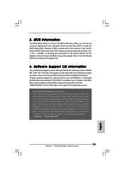
...® to activate the devices. 4.2.3 Utilities Menu The Utilities Menu shows the applications software that came with Intel LGA 775 socket, which is enabled in this Live Demo, you may contact your computer. Chapter 4 Software Support 4.1 Install Operating System This motherboard supports various Microsoft® Windows® operating systems: 98 / ME / 2000 / XP / XP 64-bit. Because motherboard settings and hardware options vary, use the setup procedures in your dealer...
...® to activate the devices. 4.2.3 Utilities Menu The Utilities Menu shows the applications software that came with Intel LGA 775 socket, which is enabled in this Live Demo, you may contact your computer. Chapter 4 Software Support 4.1 Install Operating System This motherboard supports various Microsoft® Windows® operating systems: 98 / ME / 2000 / XP / XP 64-bit. Because motherboard settings and hardware options vary, use the setup procedures in your dealer...
Quick Installation Guide
Page 2
... Chassis Speaker Header (SPEAKER 1) 22 USB 2.0 Header (USB67, Blue) 23 SATA2_EN5 24 USB 2.0 Header (USB45, Blue) 25 Clear CMOS Jumper (CLRCMOS1) 26 Infrared Module Connector (IR1) 27 Floppy Connector (FLOPPY1) 28 Game Port Header (GAME1) 29 JR1 JL1 Jumper 30 Front Panel Audio Header (AUDIO1) 31 PCI Slots (PCI1- 3) 32 PCIEX1_EN1 - 4 33 BIOS FWH Chip 34 PCI Express Slot (PCIE2) 35 PCI Express Slot (PCIE1) 36 SLI / XFIRE Power Connector 37 Internal Audio Connector: CD1 (Black) 38 ATX Power Connector (ATXPWR1) 2 ASRock 775i915P-SATA2 Motherboard Orange) 8 2 x 184-pin DDR DIMM Slots (Dual Channel...
... Chassis Speaker Header (SPEAKER 1) 22 USB 2.0 Header (USB67, Blue) 23 SATA2_EN5 24 USB 2.0 Header (USB45, Blue) 25 Clear CMOS Jumper (CLRCMOS1) 26 Infrared Module Connector (IR1) 27 Floppy Connector (FLOPPY1) 28 Game Port Header (GAME1) 29 JR1 JL1 Jumper 30 Front Panel Audio Header (AUDIO1) 31 PCI Slots (PCI1- 3) 32 PCIEX1_EN1 - 4 33 BIOS FWH Chip 34 PCI Express Slot (PCIE2) 35 PCI Express Slot (PCIE1) 36 SLI / XFIRE Power Connector 37 Internal Audio Connector: CD1 (Black) 38 ATX Power Connector (ATXPWR1) 2 ASRock 775i915P-SATA2 Motherboard Orange) 8 2 x 184-pin DDR DIMM Slots (Dual Channel...

Quick Installation Guide
Page 3
... Speaker (Black) 5 Central / Bass (Orange) 6 Line In (Light Blue) *7 Front Speaker (Lime) 8 Microphone (Pink) 9 USB 2.0 Ports (USB01) 10 USB 2.0 Ports (USB23) 11 Serial Port: COM1 12 PS/2 Keyboard Port (Purple) 13 PS/2 Mouse Port (Green) * If you use 2-channel speaker, please connect the speaker's plug into "Front Speaker Jack". See the table below for Audio Output Connection Audio Output Channels Front Speaker Rear Speaker Central / Bass (No. 7) (No. 4) (No. 5) 2 V -- -- 4 V V -- 6 V V V 8 V V V Side Speaker (No. 3) ---V 3 ASRock 775i915P-SATA2 Motherboard English...
... Speaker (Black) 5 Central / Bass (Orange) 6 Line In (Light Blue) *7 Front Speaker (Lime) 8 Microphone (Pink) 9 USB 2.0 Ports (USB01) 10 USB 2.0 Ports (USB23) 11 Serial Port: COM1 12 PS/2 Keyboard Port (Purple) 13 PS/2 Mouse Port (Green) * If you use 2-channel speaker, please connect the speaker's plug into "Front Speaker Jack". See the table below for Audio Output Connection Audio Output Channels Front Speaker Rear Speaker Central / Bass (No. 7) (No. 4) (No. 5) 2 V -- -- 4 V V -- 6 V V V 8 V V V Side Speaker (No. 3) ---V 3 ASRock 775i915P-SATA2 Motherboard English...
Quick Installation Guide
Page 6
..."Plug and Play" - Drivers, Utilities, AntiVirus Software - ACPI 1.1 Compliance Wake Up Events - Supports jumperfree - Voltage Monitoring: +12V, +5V, +3.3V, Vcore - CPU Overheat Shutdown to Protect CPU Life - Front panel audio connector - 2 x USB 2.0 headers (support 4 USB 2.0 ports) (see CAUTION 8) - Chassis Temperature Sensing - FCC, CE, WHQL English 6 ASRock 775i915P-SATA2 Motherboard SLI/XFIRE power connector - CPU Fan Tachometer - Connector BIOS Feature Support CD Hardware Monitor OS Certifications - 4 x Serial ATA 1.5Gb/s connectors (No Support for "RAID" and "Hot Plug...
..."Plug and Play" - Drivers, Utilities, AntiVirus Software - ACPI 1.1 Compliance Wake Up Events - Supports jumperfree - Voltage Monitoring: +12V, +5V, +3.3V, Vcore - CPU Overheat Shutdown to Protect CPU Life - Front panel audio connector - 2 x USB 2.0 headers (support 4 USB 2.0 ports) (see CAUTION 8) - Chassis Temperature Sensing - FCC, CE, WHQL English 6 ASRock 775i915P-SATA2 Motherboard SLI/XFIRE power connector - CPU Fan Tachometer - Connector BIOS Feature Support CD Hardware Monitor OS Certifications - 4 x Serial ATA 1.5Gb/s connectors (No Support for "RAID" and "Hot Plug...
Quick Installation Guide
Page 7
... the heatsink when you can successfully install the VGA driver. 7 ASRock 775i915P-SATA2 Motherboard English To improve heat dissipation, remember to perform over-clocking. Because of "Device Manager". Although this motherboard supports both stereo and mono modes. Besides, after installing Windows 98 / ME, two display adapter controllers will appear in the Support CD. 2. Before you install PCI Express VGA card to the "Supported PCI Express VGA Card List for proper installation. 3. If you resume the system, please check if the CPU fan...
... the heatsink when you can successfully install the VGA driver. 7 ASRock 775i915P-SATA2 Motherboard English To improve heat dissipation, remember to perform over-clocking. Because of "Device Manager". Although this motherboard supports both stereo and mono modes. Besides, after installing Windows 98 / ME, two display adapter controllers will appear in the Support CD. 2. Before you install PCI Express VGA card to the "Supported PCI Express VGA Card List for proper installation. 3. If you resume the system, please check if the CPU fan...

Quick Installation Guide
Page 18
... your IDE device vendor for the details. ASRock 775i915P-SATA2 Motherboard English It is plugged into Pin1 side of the connector. The current SATA II interface allows up to the SATA / SATAII hard disk or the SATA / SATAII connector on the motherboard. Serial ATA (SATA) Data Cable 18 Either end of the motherboard! Do NOT place jumper caps over the headers and connectors will cause permanent damage of the SATA data cable can be connected...
... your IDE device vendor for the details. ASRock 775i915P-SATA2 Motherboard English It is plugged into Pin1 side of the connector. The current SATA II interface allows up to the SATA / SATAII hard disk or the SATA / SATAII connector on the motherboard. Serial ATA (SATA) Data Cable 18 Either end of the motherboard! Do NOT place jumper caps over the headers and connectors will cause permanent damage of the SATA data cable can be connected...
Quick Installation Guide
Page 21
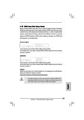
... want to enable SATAII 3.0GB/s, please remove the jumpers from pin 3 and pin 4. HITACHI Please use the Feature Tool, a DOS-bootable tool, for the updates. 21 ASRock 775i915P-SATA2 Motherboard English On the other hand, if you want to enable SATAII 3.0GB/s, please remove the jumpers from pin 5 and pin 6. Some default setting of different vendors, the jumper pin setting methods may not be enabled. 2.10 SATAII Hard Disk Setup Guide Before installing SATAII hard disk to SATAII mode in...
... want to enable SATAII 3.0GB/s, please remove the jumpers from pin 3 and pin 4. HITACHI Please use the Feature Tool, a DOS-bootable tool, for the updates. 21 ASRock 775i915P-SATA2 Motherboard English On the other hand, if you want to enable SATAII 3.0GB/s, please remove the jumpers from pin 5 and pin 6. Some default setting of different vendors, the jumper pin setting methods may not be enabled. 2.10 SATAII Hard Disk Setup Guide Before installing SATAII hard disk to SATAII mode in...
Quick Installation Guide
Page 23
... file. The Support CD that came with the motherboard contains necessary drivers and useful utilities that Intel has released. "LGA 775 CPU Installation Live Demo" This motherboard is equipped with its test routines. You may check this Live Demo in your CD-ROM drive. If you a clear installation guide through the following path: ..\ MPEGAV \ LGA775INST.DAT 23 ASRock 775i915P-SATA2 Motherboard English If the Main Menu does not appear automatically, locate...
... file. The Support CD that came with the motherboard contains necessary drivers and useful utilities that Intel has released. "LGA 775 CPU Installation Live Demo" This motherboard is equipped with its test routines. You may check this Live Demo in your CD-ROM drive. If you a clear installation guide through the following path: ..\ MPEGAV \ LGA775INST.DAT 23 ASRock 775i915P-SATA2 Motherboard English If the Main Menu does not appear automatically, locate...


