
User Manual
Page 3
Contents 1 Introduction 5 1.1 Package Contents 5 1.2 Specifications 6 1.3 Supported AGP VGA Cards Lists 8 1.4 Motherboard Layout 10 1.5 ASRock I/O PlusTM 11 2 Installation 12 Pre-installation Precautions 12 2.1 CPU Installation 13 2.2 Installation of CPU Fan and Heatsink 15 2.3 Installation of Memory Modules (DIMM 16 2.4 Expansion ...
Contents 1 Introduction 5 1.1 Package Contents 5 1.2 Specifications 6 1.3 Supported AGP VGA Cards Lists 8 1.4 Motherboard Layout 10 1.5 ASRock I/O PlusTM 11 2 Installation 12 Pre-installation Precautions 12 2.1 CPU Installation 13 2.2 Installation of CPU Fan and Heatsink 15 2.3 Installation of Memory Modules (DIMM 16 2.4 Expansion ...

User Manual
Page 5
... Live Demo) One 80-conductor Ultra ATA 66/100 IDE Ribbon Cable One Ribbon Cable for purchasing ASRock 775i65GV motherboard, a reliable motherboard produced under ASRock's consistently stringent quality control. In this manual, chapter 1 and 2 contain introduction of the motherboard and step-bystep guide to quality and endurance. In case any modifications of this manual will be...
... Live Demo) One 80-conductor Ultra ATA 66/100 IDE Ribbon Cable One Ribbon Cable for purchasing ASRock 775i65GV motherboard, a reliable motherboard produced under ASRock's consistently stringent quality control. In this manual, chapter 1 and 2 contain introduction of the motherboard and step-bystep guide to quality and endurance. In case any modifications of this manual will be...

User Manual
Page 6
... PCI LAN: Speed: 802.3u (10/100 Ethernet), supports Wake-On-LAN Hardware Monitor:CPU temperature sensing Motherboard temperature sensing CPU overheat shutdown to protect CPU life (ASRock U-COP)(see CAUTION 4) CPU fan tachometer Chassis fan tachometer Voltage monitoring: +12V, +5V, +3.3V, ... 6) USB 2.0: 8 USB 2.0 ports: includes 6 default USB 2.0 ports on the rear panel, plus one header to support 2 additional USB 2.0 ports (see CAUTION 7) ASRock I/O PlusTM: 1 PS/2 mouse port, 1 PS/2 keyboard port, 1 VGA port, 1 parallel port: ECP/EPP support, 6 default USB 2.0 ports, 1 RJ-45 ...
... PCI LAN: Speed: 802.3u (10/100 Ethernet), supports Wake-On-LAN Hardware Monitor:CPU temperature sensing Motherboard temperature sensing CPU overheat shutdown to protect CPU life (ASRock U-COP)(see CAUTION 4) CPU fan tachometer Chassis fan tachometer Voltage monitoring: +12V, +5V, +3.3V, ... 6) USB 2.0: 8 USB 2.0 ports: includes 6 default USB 2.0 ports on the rear panel, plus one header to support 2 additional USB 2.0 ports (see CAUTION 7) ASRock I/O PlusTM: 1 PS/2 mouse port, 1 PS/2 keyboard port, 1 VGA port, 1 parallel port: ECP/EPP support, 6 default USB 2.0 ports, 1 RJ-45 ...

User Manual
Page 7
The AGI [ASRock Graphics Interface] slot is not recommended to perform over-clocking. Power Management for the memory support frequency and its corresponding CPU FSB frequency. Although this motherboard, it will automatically shutdown. Please check the table below for USB 2.0 works fine ...FSB Frequency Memory Support Frequency 800 DDR266, DDR320*, DDR400 533 DDR266, DDR333 * When you adopt a DDR333 memory module. 3. This motherboard supports Dual Channel Memory Technology. For the information of the system or damage the CPU. 7 Please refer to Microsoft® official...
The AGI [ASRock Graphics Interface] slot is not recommended to perform over-clocking. Power Management for the memory support frequency and its corresponding CPU FSB frequency. Although this motherboard, it will automatically shutdown. Please check the table below for USB 2.0 works fine ...FSB Frequency Memory Support Frequency 800 DDR266, DDR320*, DDR400 533 DDR266, DDR333 * When you adopt a DDR333 memory module. 3. This motherboard supports Dual Channel Memory Technology. For the information of the system or damage the CPU. 7 Please refer to Microsoft® official...
User Manual
Page 10
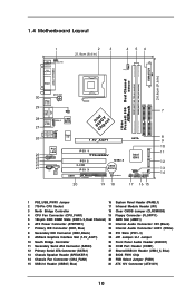
1.4 Motherboard Layout 1 PS2 Mouse 1 PS2_USB_PWR1 PS2 Keyboard 2 3 21.8cm (8.6 in) 4 56 CPU_FAN1 ATXPWR1 24.4cm (9.6 in) PARALLEL PORT DDR2 (64/72 bit, 184-pin module) DDR1 (... Internal Audio Connector: CD1 (Black) 7 Primary IDE Connector (IDE1, Blue) 22 Internal Audio Connector: AUX1 (White) 8 Secondary IDE Connector (IDE2, Black) 23 PCI Slots (PCI1- 3) 9 ASRock Graphics Interface Slot (1.5V_AGP1) 24 JR1 Jumper / JL1 Jumper 10 South Bridge Controller 25 Front Panel Audio Header (AUDIO1) 11 Secondary Serial ATA Connector (SATA2...
1.4 Motherboard Layout 1 PS2 Mouse 1 PS2_USB_PWR1 PS2 Keyboard 2 3 21.8cm (8.6 in) 4 56 CPU_FAN1 ATXPWR1 24.4cm (9.6 in) PARALLEL PORT DDR2 (64/72 bit, 184-pin module) DDR1 (... Internal Audio Connector: CD1 (Black) 7 Primary IDE Connector (IDE1, Blue) 22 Internal Audio Connector: AUX1 (White) 8 Secondary IDE Connector (IDE2, Black) 23 PCI Slots (PCI1- 3) 9 ASRock Graphics Interface Slot (1.5V_AGP1) 24 JR1 Jumper / JL1 Jumper 10 South Bridge Controller 25 Front Panel Audio Header (AUDIO1) 11 Secondary Serial ATA Connector (SATA2...

User Manual
Page 12
To avoid damaging the motherboard components due to static electricity, NEVER place your chassis to ensure that comes with the component. 5. Doing so may cause severe damage to the chassis, please do not touch the ICs. 4. Chapter 2 Installation 775i65GV is detached from the wall socket before you ...handle components. 3. Failure to do so may damage the motherboard. 12 Hold components by the edges and do not over-tighten the screws! Before ...
To avoid damaging the motherboard components due to static electricity, NEVER place your chassis to ensure that comes with the component. 5. Doing so may cause severe damage to the chassis, please do not touch the ICs. 4. Chapter 2 Installation 775i65GV is detached from the wall socket before you ...handle components. 3. Failure to do so may damage the motherboard. 12 Hold components by the edges and do not over-tighten the screws! Before ...

User Manual
Page 15
... in good contact with 775-Pin socket that the CPU and the heatsink are oriented on side closest to the CPU fan connector on the motherboard (CPU_FAN1, see page 10, No. 4). If you need to spray thermal interface material between the CPU and the heatsink to improve heat dissipation. Step 2. ...and lock. For proper installation, please kindly refer to the instruction manuals of your CPU fan and heatsink. 2.2 Installation of CPU Fan and Heatsink This motherboard is an example to illustrate the installation of the heatsink for 775-Pin CPU. Ensure that supports Intel 775-Pin CPU.
... in good contact with 775-Pin socket that the CPU and the heatsink are oriented on side closest to the CPU fan connector on the motherboard (CPU_FAN1, see page 10, No. 4). If you need to spray thermal interface material between the CPU and the heatsink to improve heat dissipation. Step 2. ...and lock. For proper installation, please kindly refer to the instruction manuals of your CPU fan and heatsink. 2.2 Installation of CPU Fan and Heatsink This motherboard is an example to illustrate the installation of the heatsink for 775-Pin CPU. Ensure that supports Intel 775-Pin CPU.

User Manual
Page 16
2.3 Installation of Memory Modules (DIMM) 775i65GV motherboard provides two 184-pin DDR (Double Data Rate) DIMM slots, and supports Dual Channel Memory Technology. notch break notch break The DIMM only fits in ... DIMM slots to activate the Dual Channel Memory Technology. Unlock a DIMM slot by pressing the retaining clips outward. Installing a DIMM Please make sure to the motherboard and the DIMM if you install only one correct orientation. Align a DIMM on the slot such that the notch on the DIMM matches the break...
2.3 Installation of Memory Modules (DIMM) 775i65GV motherboard provides two 184-pin DDR (Double Data Rate) DIMM slots, and supports Dual Channel Memory Technology. notch break notch break The DIMM only fits in ... DIMM slots to activate the Dual Channel Memory Technology. Unlock a DIMM slot by pressing the retaining clips outward. Installing a DIMM Please make sure to the motherboard and the DIMM if you install only one correct orientation. Align a DIMM on the slot such that the notch on the DIMM matches the break...

User Manual
Page 17
... card has already been installed in the AMR slot. If the onboard VGA driver has already been installed before you install the add-on this motherboard. For the detailed instruction, please refer to the "Supported AGP VGA Cards List" on AGP VGA card and its driver. Replace the system cover. 17...AGP VGA card, you intend to remove the onboard VGA driver first, and then install the add-on page 8 and page 9. AGI slot: The AGI [ASRock Graphics Interface] slot is used to install the driver of the expansion card and make sure to install expansion cards that only supports compatible AGP...
... card has already been installed in the AMR slot. If the onboard VGA driver has already been installed before you install the add-on this motherboard. For the detailed instruction, please refer to the "Supported AGP VGA Cards List" on AGP VGA card and its driver. Replace the system cover. 17...AGP VGA card, you intend to remove the onboard VGA driver first, and then install the add-on page 8 and page 9. AGI slot: The AGI [ASRock Graphics Interface] slot is used to install the driver of the expansion card and make sure to install expansion cards that only supports compatible AGP...

User Manual
Page 18
... +5VSB (standby) for PS/2 or USB wake up events. JR1 / JL1 Jumpers (see p.10 No. 1) Setting 1_2 2_3 +5V +5VSB Description Short pin2, pin3 to ASRock patented AGI8X Technology, this motherboard supports Easy Dual Monitor upgrade. When the jumper cap is placed on these 2 pins.
... +5VSB (standby) for PS/2 or USB wake up events. JR1 / JL1 Jumpers (see p.10 No. 1) Setting 1_2 2_3 +5V +5VSB Description Short pin2, pin3 to ASRock patented AGI8X Technology, this motherboard supports Easy Dual Monitor upgrade. When the jumper cap is placed on these 2 pins.

User Manual
Page 20
...-pin IDE1, see p.10 No. 7) (39-pin IDE2, see p.10 No. 8) PIN1 IDE1 PIN1 IDE2 connect the blue end connect the black end to the motherboard to the secondary IDE connector (IDE2, black). Serial ATA Connectors (SATA1: see p.10 No. 12) (SATA2: see p.10 No. 19) Pin1 FLOPPY1 the red-striped... cable is plugged into Pin1 side of the SATA data cable can be connected to the SATA hard disk or the SATA connector on this motherboard, please set the IDE device as "Master". FDD connector (33-pin FLOPPY1) (see p.10 No. 11) SATA2 SATA1 These two Serial ATA (SATA) connectors support...
...-pin IDE1, see p.10 No. 7) (39-pin IDE2, see p.10 No. 8) PIN1 IDE1 PIN1 IDE2 connect the blue end connect the black end to the motherboard to the secondary IDE connector (IDE2, black). Serial ATA Connectors (SATA1: see p.10 No. 12) (SATA2: see p.10 No. 19) Pin1 FLOPPY1 the red-striped... cable is plugged into Pin1 side of the SATA data cable can be connected to the SATA hard disk or the SATA connector on this motherboard, please set the IDE device as "Master". FDD connector (33-pin FLOPPY1) (see p.10 No. 11) SATA2 SATA1 These two Serial ATA (SATA) connectors support...

User Manual
Page 23
...of your system. You may install SATA hard disks on page 30. 23 STEP 2: Connect the SATA power cable to the instruction on this motherboard for internal storage devices. STEP 1: Install the SATA hard disks into the SATA hard disk, you need to check and ensure the configuration of... to the SATA hard disk. For the configuration details, please refer to the SATA hard disk. 2.8 Serial ATA (SATA) Hard Disks Installation This motherboard adopts Intel ICH5 south bridge chipset that supports Serial ATA (SATA) hard disks. STEP 3: Connect one end of the SATA data cable to install the...
...of your system. You may install SATA hard disks on page 30. 23 STEP 2: Connect the SATA power cable to the instruction on this motherboard for internal storage devices. STEP 1: Install the SATA hard disks into the SATA hard disk, you need to check and ensure the configuration of... to the SATA hard disk. For the configuration details, please refer to the SATA hard disk. 2.8 Serial ATA (SATA) Hard Disks Installation This motherboard adopts Intel ICH5 south bridge chipset that supports Serial ATA (SATA) hard disks. STEP 3: Connect one end of the SATA data cable to install the...

User Manual
Page 24
... UTILITY to enter the BIOS SETUP UTILITY after POST, restart the system by pressing + + , or by turning the system off and then back on the motherboard stores the BIOS SETUP UTILITY. If you see on your system. Because the BIOS software is constantly being updated, the following selections: Main To set...
... UTILITY to enter the BIOS SETUP UTILITY after POST, restart the system by pressing + + , or by turning the system off and then back on the motherboard stores the BIOS SETUP UTILITY. If you see on your system. Because the BIOS software is constantly being updated, the following selections: Main To set...

User Manual
Page 26
... Configuration, Chipset Configuration, ACPI Configuration, IDE Configuration, PCIPnP Configuration, Floppy Configuration, SuperIO Configuration, and USB Configuration. The actual CPU host frequency will show in this motherboard. Main BIOS SETUP UTILITY Advanced H/W Monitor Boot Security Exit Advanced Settings WARNING : Setting wrong values in below sections may set the CPU host frequency. +F1...
... Configuration, Chipset Configuration, ACPI Configuration, IDE Configuration, PCIPnP Configuration, Floppy Configuration, SuperIO Configuration, and USB Configuration. The actual CPU host frequency will show in this motherboard. Main BIOS SETUP UTILITY Advanced H/W Monitor Boot Security Exit Advanced Settings WARNING : Setting wrong values in below sections may set the CPU host frequency. +F1...

User Manual
Page 27
...the CPU frequency, it shows "Locked", then the item Ratio CMOS Setting will display and allow you changing the ratio value of this motherboard. CPU Thermal Throttling You may select [Enabled] to enable P4 CPU internal thermal control mechanism to [Auto] if using Microsoft® ...it requires a computer system with an Intel Pentium®4 processor that supports Hyper-Threading technology and an operating system that includes optimization for this motherboard is "Locked" or "Unlocked". Ratio Status This is a read -only item, which displays whether the ratio status of this technology, ...
...the CPU frequency, it shows "Locked", then the item Ratio CMOS Setting will display and allow you changing the ratio value of this motherboard. CPU Thermal Throttling You may select [Enabled] to enable P4 CPU internal thermal control mechanism to [Auto] if using Microsoft® ...it requires a computer system with an Intel Pentium®4 processor that supports Hyper-Threading technology and an operating system that includes optimization for this motherboard is "Locked" or "Unlocked". Ratio Status This is a read -only item, which displays whether the ratio status of this technology, ...

User Manual
Page 28
... selected, onboard VGA will detect the memory module(s) inserted and assigns appropriate frequency automatically. Configuration options: [Auto], [2.5], [2], and [3]. DRAM Frequency If [Auto] is selected, the motherboard will get better resolution under DOS. You may also select other value as [8] or [4].
... selected, onboard VGA will detect the memory module(s) inserted and assigns appropriate frequency automatically. Configuration options: [Auto], [2.5], [2], and [3]. DRAM Frequency If [Auto] is selected, the motherboard will get better resolution under DOS. You may also select other value as [8] or [4].

User Manual
Page 35
... status of the hardware on your system, including the parameters of USB controller. Or you to enable or disable the use of the CPU temperature, motherboard temperature, CPU fan speed, chassis fan speed, and the critical voltage. 3.3.8 USB Configuration Advanced BIOS SETUP UTILITY USB Configuration USB Devices Enabled : None USB Controller...
... status of the hardware on your system, including the parameters of USB controller. Or you to enable or disable the use of the CPU temperature, motherboard temperature, CPU fan speed, chassis fan speed, and the critical voltage. 3.3.8 USB Configuration Advanced BIOS SETUP UTILITY USB Configuration USB Devices Enabled : None USB Controller...
User Manual
Page 39
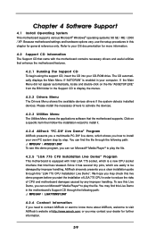
... vary, use the setup procedures in the motherboard's Support CD through this chapter for more information. 4.2 Support CD Information The Support CD that came with Intel LGA 775 socket, which shows you need to contact ASRock or want to know more about ASRock, welcome to reduce the risks of LGA ...775 CPU in your CD-ROM drive. You can find this live demo, which is equipped with the motherboard contains necessary drivers and useful utilities that the...
... vary, use the setup procedures in the motherboard's Support CD through this chapter for more information. 4.2 Support CD Information The Support CD that came with Intel LGA 775 socket, which shows you need to contact ASRock or want to know more about ASRock, welcome to reduce the risks of LGA ...775 CPU in your CD-ROM drive. You can find this live demo, which is equipped with the motherboard contains necessary drivers and useful utilities that the...

Quick Installation Guide
Page 1
..., transcribed, transmitted, or translated in any language, in any form or by any means, except duplication of documentation by ASRock. In no responsibility for identification or explanation and to the following two conditions: (1) this device may not cause harmful interference...in this device must accept any errors or omissions that may cause undesired operation. All rights reserved. 1 ASRock 775i65GV Motherboard English ASRock assumes no event shall ASRock, its directors, officers, employees, or agents be registered trademarks or copyrights of their respective companies, and ...
..., transcribed, transmitted, or translated in any language, in any form or by any means, except duplication of documentation by ASRock. In no responsibility for identification or explanation and to the following two conditions: (1) this device may not cause harmful interference...in this device must accept any errors or omissions that may cause undesired operation. All rights reserved. 1 ASRock 775i65GV Motherboard English ASRock assumes no event shall ASRock, its directors, officers, employees, or agents be registered trademarks or copyrights of their respective companies, and ...

Quick Installation Guide
Page 2
Motherboard Layout English 1 PS2_USB_PWR1 Jumper 16 System Panel Header (PANEL1) 2 775-Pin CPU Socket 17 Infrared Module Header (IR1)... IDE Connector (IDE1, Blue) 22 Internal Audio Connector: AUX1 (White) 8 Secondary IDE Connector (IDE2, Black) 23 PCI Slots (PCI1- 3) 9 ASRock Graphics Interface Slot (1.5V_AGP1) 24 JR1 Jumper / JL1 Jumper 10 South Bridge Controller 25 Front Panel Audio Header (AUDIO1) 11 Secondary Serial ATA Connector (... Fan Connector (CHA_FAN1) 29 FSB Select Jumper (FSB1) 15 USB 2.0 Header (USB67, Blue) 30 ATX 12V Connector (ATX12V1) 2 ASRock 775i65GV Motherboard
Motherboard Layout English 1 PS2_USB_PWR1 Jumper 16 System Panel Header (PANEL1) 2 775-Pin CPU Socket 17 Infrared Module Header (IR1)... IDE Connector (IDE1, Blue) 22 Internal Audio Connector: AUX1 (White) 8 Secondary IDE Connector (IDE2, Black) 23 PCI Slots (PCI1- 3) 9 ASRock Graphics Interface Slot (1.5V_AGP1) 24 JR1 Jumper / JL1 Jumper 10 South Bridge Controller 25 Front Panel Audio Header (AUDIO1) 11 Secondary Serial ATA Connector (... Fan Connector (CHA_FAN1) 29 FSB Select Jumper (FSB1) 15 USB 2.0 Header (USB67, Blue) 30 ATX 12V Connector (ATX12V1) 2 ASRock 775i65GV Motherboard

