
User Manual
Page 6
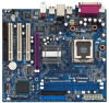
1.2 Specifications Platform: Micro ATX Form Factor: 9.6-in x 8.6-in, 24.4 cm x 21.8 cm CPU: 775-Pin Socket supporting Intel® Pentium® 4 / Celeron® processor (in 775-land LGA package) Chipsets: North Bridge: Intel® 865GV chipset, FSB @ 800 / 533 MHz, supports Hyper-....3u (10/100 Ethernet), supports Wake-On-LAN Hardware Monitor:CPU temperature sensing Motherboard temperature sensing CPU overheat shutdown to protect CPU life (ASRock U-COP)(see CAUTION 4) CPU fan tachometer Chassis fan tachometer Voltage monitoring: +12V, +5V, +3.3V, Vcore PCI slots: 3 PCI ...
1.2 Specifications Platform: Micro ATX Form Factor: 9.6-in x 8.6-in, 24.4 cm x 21.8 cm CPU: 775-Pin Socket supporting Intel® Pentium® 4 / Celeron® processor (in 775-land LGA package) Chipsets: North Bridge: Intel® 865GV chipset, FSB @ 800 / 533 MHz, supports Hyper-....3u (10/100 Ethernet), supports Wake-On-LAN Hardware Monitor:CPU temperature sensing Motherboard temperature sensing CPU overheat shutdown to protect CPU life (ASRock U-COP)(see CAUTION 4) CPU fan tachometer Chassis fan tachometer Voltage monitoring: +12V, +5V, +3.3V, Vcore PCI slots: 3 PCI ...
User Manual
Page 10
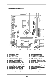
...HDLED RESET USB67 20 19 18 17 16 15 7 8 9 10 11 12 13 14 1 PS2_USB_PWR1 Jumper 16 System Panel Header (PANEL1) 2 775-Pin CPU Socket 17 Infrared Module Header (IR1) 3 North Bridge Controller 18 Clear CMOS Jumper (CLRCMOS0) 4 CPU Fan Connector (CPU_FAN1) 19 Floppy Connector (FLOPPY1)... Connector (IDE1, Blue) 22 Internal Audio Connector: AUX1 (White) 8 Secondary IDE Connector (IDE2, Black) 23 PCI Slots (PCI1- 3) 9 ASRock Graphics Interface Slot (1.5V_AGP1) 24 JR1 Jumper / JL1 Jumper 10 South Bridge Controller 25 Front Panel Audio Header (AUDIO1) 11 Secondary Serial ATA Connector...
...HDLED RESET USB67 20 19 18 17 16 15 7 8 9 10 11 12 13 14 1 PS2_USB_PWR1 Jumper 16 System Panel Header (PANEL1) 2 775-Pin CPU Socket 17 Infrared Module Header (IR1) 3 North Bridge Controller 18 Clear CMOS Jumper (CLRCMOS0) 4 CPU Fan Connector (CPU_FAN1) 19 Floppy Connector (FLOPPY1)... Connector (IDE1, Blue) 22 Internal Audio Connector: AUX1 (White) 8 Secondary IDE Connector (IDE2, Black) 23 PCI Slots (PCI1- 3) 9 ASRock Graphics Interface Slot (1.5V_AGP1) 24 JR1 Jumper / JL1 Jumper 10 South Bridge Controller 25 Front Panel Audio Header (AUDIO1) 11 Secondary Serial ATA Connector...

User Manual
Page 13
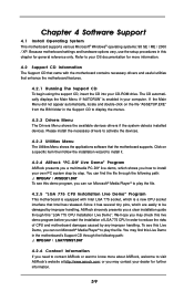
...Step 1-3. Locate Pin1 and the two orientation key notches. Pin1 orientation key notch orientation key notch Pin1 alignment key alignment key 775-Pin CPU 775-Pin Socket 13 black line black line Orient the CPU with black lines. Step 1-2. 2.1 CPU Installation For the installation of Intel... 775-Pin CPU, please follow the steps below. 775-Pin Socket Overview Before you insert the 775-Pin CPU into the socket if above situation is any bent pin on the hook to fully open position at ...
...Step 1-3. Locate Pin1 and the two orientation key notches. Pin1 orientation key notch orientation key notch Pin1 alignment key alignment key 775-Pin CPU 775-Pin Socket 13 black line black line Orient the CPU with black lines. Step 1-2. 2.1 CPU Installation For the installation of Intel... 775-Pin CPU, please follow the steps below. 775-Pin Socket Overview Before you insert the 775-Pin CPU into the socket if above situation is any bent pin on the hook to fully open position at ...

User Manual
Page 15
... connector on the motherboard (CPU_FAN1, see page 10, No. 4). Step 1. Step 4. Place the heatsink onto the socket. Step 5. Please adopt the type of heatsink and cooling fan compliant with remaining fasteners. Step 2. Repeat with Intel 775-Pin CPU to dissipate heat. 2.2 Installation of CPU Fan and Heatsink This motherboard is an example...
... connector on the motherboard (CPU_FAN1, see page 10, No. 4). Step 1. Step 4. Place the heatsink onto the socket. Step 5. Please adopt the type of heatsink and cooling fan compliant with remaining fasteners. Step 2. Repeat with Intel 775-Pin CPU to dissipate heat. 2.2 Installation of CPU Fan and Heatsink This motherboard is an example...
User Manual
Page 39
... 2000 / XP. or you can run Microsoft® Media Player® to visit ASRock's website at http://www.asrock.com; The CD automatically displays the Main Menu if "AUTORUN" is a new CPU socket interface that the motherboard supports. Click on the file "ASSETUP.EXE" from the BIN ...information. 4.2 Support CD Information The Support CD that came with Intel LGA 775 socket, which shows you need to contact ASRock or want to know more about ASRock, welcome to play the file. 4.2.5 "LGA 775 CPU Installation Live Demo" Program This motherboard is equipped with the motherboard contains...
... 2000 / XP. or you can run Microsoft® Media Player® to visit ASRock's website at http://www.asrock.com; The CD automatically displays the Main Menu if "AUTORUN" is a new CPU socket interface that the motherboard supports. Click on the file "ASSETUP.EXE" from the BIN ...information. 4.2 Support CD Information The Support CD that came with Intel LGA 775 socket, which shows you need to contact ASRock or want to know more about ASRock, welcome to play the file. 4.2.5 "LGA 775 CPU Installation Live Demo" Program This motherboard is equipped with the motherboard contains...

Quick Installation Guide
Page 2
Motherboard Layout English 1 PS2_USB_PWR1 Jumper 16 System Panel Header (PANEL1) 2 775-Pin CPU Socket 17 Infrared Module Header (IR1) 3 North Bridge Controller 18 Clear CMOS Jumper (CLRCMOS0) 4 ...IDE1, Blue) 22 Internal Audio Connector: AUX1 (White) 8 Secondary IDE Connector (IDE2, Black) 23 PCI Slots (PCI1- 3) 9 ASRock Graphics Interface Slot (1.5V_AGP1) 24 JR1 Jumper / JL1 Jumper 10 South Bridge Controller 25 Front Panel Audio Header (AUDIO1) 11 Secondary Serial... Select Jumper (FSB1) 15 USB 2.0 Header (USB67, Blue) 30 ATX 12V Connector (ATX12V1) 2 ASRock 775i65GV Motherboard
Motherboard Layout English 1 PS2_USB_PWR1 Jumper 16 System Panel Header (PANEL1) 2 775-Pin CPU Socket 17 Infrared Module Header (IR1) 3 North Bridge Controller 18 Clear CMOS Jumper (CLRCMOS0) 4 ...IDE1, Blue) 22 Internal Audio Connector: AUX1 (White) 8 Secondary IDE Connector (IDE2, Black) 23 PCI Slots (PCI1- 3) 9 ASRock Graphics Interface Slot (1.5V_AGP1) 24 JR1 Jumper / JL1 Jumper 10 South Bridge Controller 25 Front Panel Audio Header (AUDIO1) 11 Secondary Serial... Select Jumper (FSB1) 15 USB 2.0 Header (USB67, Blue) 30 ATX 12V Connector (ATX12V1) 2 ASRock 775i65GV Motherboard

Quick Installation Guide
Page 5
... Specifications Platform: Micro ATX Form Factor: 9.6-in x 8.6-in, 24.4 cm x 21.8 cm CPU: 775-Pin Socket supporting Intel® Pentium® 4 / Celeron® processor (in 775-land LGA package) Chipsets: North Bridge: Intel® 865GV chipset, FSB @ 800 / 533 MHz, ...ports on the rear panel, plus one header to support 2 additional USB 2.0 ports (see CAUTION 7) ASRock I/O PlusTM: 1 PS/2 mouse port, 1 PS/2 keyboard port, 1 VGA port, 1 parallel port: ECP/EPP support, 6 default USB 2.0 ports, 1 RJ-45 port, Audio Jack: Line In / Line Out / Microphone 5 ASRock 775i65GV Motherboard
... Specifications Platform: Micro ATX Form Factor: 9.6-in x 8.6-in, 24.4 cm x 21.8 cm CPU: 775-Pin Socket supporting Intel® Pentium® 4 / Celeron® processor (in 775-land LGA package) Chipsets: North Bridge: Intel® 865GV chipset, FSB @ 800 / 533 MHz, ...ports on the rear panel, plus one header to support 2 additional USB 2.0 ports (see CAUTION 7) ASRock I/O PlusTM: 1 PS/2 mouse port, 1 PS/2 keyboard port, 1 VGA port, 1 parallel port: ECP/EPP support, 6 default USB 2.0 ports, 1 RJ-45 port, Audio Jack: Line In / Line Out / Microphone 5 ASRock 775i65GV Motherboard

Quick Installation Guide
Page 9
2. Hold components by the edges and do not over-tighten the screws! Otherwise, the CPU will be seriously damaged. 9 ASRock 775i65GV Motherboard English To avoid damaging the motherboard components due to use a grounded wrist strap or touch a safety grounded object before touching ...antstatic pad or in the bag that comes with the component. 5. Installation Pre-installation Precautions Take note of Intel 775-Pin CPU, please follow the steps below. 775-Pin Socket Overview Before you install motherboard components or change any bent pin on the carpet or the like. Failure to ...
2. Hold components by the edges and do not over-tighten the screws! Otherwise, the CPU will be seriously damaged. 9 ASRock 775i65GV Motherboard English To avoid damaging the motherboard components due to use a grounded wrist strap or touch a safety grounded object before touching ...antstatic pad or in the bag that comes with the component. 5. Installation Pre-installation Precautions Take note of Intel 775-Pin CPU, please follow the steps below. 775-Pin Socket Overview Before you install motherboard components or change any bent pin on the carpet or the like. Failure to ...

Quick Installation Guide
Page 10
...): Use your left hand index finger and thumb to assist in removal. 10 ASRock 775i65GV Motherboard Rotate the load lever to fully open position at approximately 100 degrees. Verify that the CPU is within the socket and properly mated to match the two orientation key notches of the...the CPU with IHS (Integrated Heat Sink) up. Step 1-2. Pin1 orientation key notch orientation key notch Pin1 alignment key alignment key 775-Pin CPU 775-Pin Socket For proper inserting, please ensure to the orient keys. Step 2-4. Disengaging the lever by using a purely vertical motion. Step 1. ...
...): Use your left hand index finger and thumb to assist in removal. 10 ASRock 775i65GV Motherboard Rotate the load lever to fully open position at approximately 100 degrees. Verify that the CPU is within the socket and properly mated to match the two orientation key notches of the...the CPU with IHS (Integrated Heat Sink) up. Step 1-2. Pin1 orientation key notch orientation key notch Pin1 alignment key alignment key 775-Pin CPU 775-Pin Socket For proper inserting, please ensure to the orient keys. Step 2-4. Disengaging the lever by using a purely vertical motion. Step 1. ...

Quick Installation Guide
Page 11
...the motherboard throughholes. Step 3. Connect fan header with fan operation or contact other components. 11 ASRock 775i65GV Motherboard English Apply thermal interface material onto center of the heatsink for 775-Pin CPU. Ensure fan cables are oriented on side closest to illustrate the installation of IHS...Step 4. Secure excess cable with tie-wrap to the instruction manuals of your CPU fan and heatsink. Place the heatsink onto the socket. Rotate the fastener clockwise, then press down lightly on fastener caps with load plate tab under retention tab of load lever. ...
...the motherboard throughholes. Step 3. Connect fan header with fan operation or contact other components. 11 ASRock 775i65GV Motherboard English Apply thermal interface material onto center of the heatsink for 775-Pin CPU. Ensure fan cables are oriented on side closest to illustrate the installation of IHS...Step 4. Secure excess cable with tie-wrap to the instruction manuals of your CPU fan and heatsink. Place the heatsink onto the socket. Rotate the fastener clockwise, then press down lightly on fastener caps with load plate tab under retention tab of load lever. ...

Quick Installation Guide
Page 20
... through the following path: ..\ MPEGAV \ LGA775INST.DAT 20 ASRock 775i65GV Motherboard English If the Main Menu does not appear automatically, locate and double-click on the file "ASSETUP.EXE" from the "BIN" folder in your computer. The Support CD that came with Intel LGA 775 socket, which shows you a step-by-step guide to...
... through the following path: ..\ MPEGAV \ LGA775INST.DAT 20 ASRock 775i65GV Motherboard English If the Main Menu does not appear automatically, locate and double-click on the file "ASSETUP.EXE" from the "BIN" folder in your computer. The Support CD that came with Intel LGA 775 socket, which shows you a step-by-step guide to...