RAID Installation Guide
Page 2
...) hard disks with RAID functions, including RAID 0, RAID 1, RAID 10, RAID 5, and Intel Matrix Storage. You may install SATA hard disks on SATA ports. 2 1. Please read the RAID configurations in the support CD. This section will guide you how to create RAID on this guide carefully according to the Intel southbridge chipset that your motherboard adopts. Guide to...
...) hard disks with RAID functions, including RAID 0, RAID 1, RAID 10, RAID 5, and Intel Matrix Storage. You may install SATA hard disks on SATA ports. 2 1. Please read the RAID configurations in the support CD. This section will guide you how to create RAID on this guide carefully according to the Intel southbridge chipset that your motherboard adopts. Guide to...
RAID Installation Guide
Page 3
...the data transfer rate of data from one logical unit. This section will introduce the basic knowledge of the RAID 0 Disk will direct all applications to the surviving drive as a single drive but at a sustained data transfer... drives of RAID This motherboard adopts Intel southbridge chipset that integrates RAID controller supporting RAID 0 / RAID 1/ Intel Matrix Storage / RAID 10 / RAID 5 function with four independent Serial ATA (SATA) channels. WARNING!! 2. Guide to configure RAID 0 / RAID 1/ Intel Matrix Storage / RAID 10 / RAID 5 settings. RAID 1 (Data Mirroring) RAID 1 is ...
...the data transfer rate of data from one logical unit. This section will introduce the basic knowledge of the RAID 0 Disk will direct all applications to the surviving drive as a single drive but at a sustained data transfer... drives of RAID This motherboard adopts Intel southbridge chipset that integrates RAID controller supporting RAID 0 / RAID 1/ Intel Matrix Storage / RAID 10 / RAID 5 function with four independent Serial ATA (SATA) channels. WARNING!! 2. Guide to configure RAID 0 / RAID 1/ Intel Matrix Storage / RAID 10 / RAID 5 settings. RAID 1 (Data Mirroring) RAID 1 is ...

User Manual
Page 3
...5 1.1 Package Contents 5 1.2 Specifications 6 1.3 Supported PCI Express VGA Card List for AGI Express Slot (PCI Express x 4 9 1.4 Motherboard Layout 10 1.5 HD 8CH I/O Panel 11 2 Installation 12 2.1 Screw Holes 12 2.2 Pre-installation Precautions 12 2.3 CPU Installation 13 2.4 Installation... Windows 2000 / Windows XP / Windows XP 64-bit With RAID Functions 30 2.14.1 Setting Up a RAID Ready System 31 2.14.2 Migrating a "RAID Ready" System to RAID 0 or RAID 1 31 2.15 Installing Windows 2000 / XP / XP 64-bit Without RAID Functions 32 3 BIOS SETUP UTILITY 33 3.1 Introduction 33 3.1.1 ...
...5 1.1 Package Contents 5 1.2 Specifications 6 1.3 Supported PCI Express VGA Card List for AGI Express Slot (PCI Express x 4 9 1.4 Motherboard Layout 10 1.5 HD 8CH I/O Panel 11 2 Installation 12 2.1 Screw Holes 12 2.2 Pre-installation Precautions 12 2.3 CPU Installation 13 2.4 Installation... Windows 2000 / Windows XP / Windows XP 64-bit With RAID Functions 30 2.14.1 Setting Up a RAID Ready System 31 2.14.2 Migrating a "RAID Ready" System to RAID 0 or RAID 1 31 2.15 Installing Windows 2000 / XP / XP 64-bit Without RAID Functions 32 3 BIOS SETUP UTILITY 33 3.1 Introduction 33 3.1.1 ...

User Manual
Page 5
... updated, the content of this manual occur, the updated version will be available on ASRock website as well. ASRock website http://www.asrock.com 1.1 Package Contents ASRock 775XFire-RAID Motherboard (ATX Form Factor: 12.0-in x 8.6-in, 30.5 cm x 21.8 cm) ASRock 775XFire-RAID Quick Installation Guide ASRock 775XFire-RAID Support CD (including LGA 775 CPU Installation Live Demo) One 80-conductor Ultra ATA...
... updated, the content of this manual occur, the updated version will be available on ASRock website as well. ASRock website http://www.asrock.com 1.1 Package Contents ASRock 775XFire-RAID Motherboard (ATX Form Factor: 12.0-in x 8.6-in, 30.5 cm x 21.8 cm) ASRock 775XFire-RAID Quick Installation Guide ASRock 775XFire-RAID Support CD (including LGA 775 CPU Installation Live Demo) One 80-conductor Ultra ATA...

User Manual
Page 8
... not recommended to perform over-clocking. If you install the PC system. 5. This motherboard supports Dual Channel Memory Technology. Please check the table on the motherboard functions properly and unplug the power cord, then plug it is detected, the system ... (PCIE x 1) function will automatically shutdown. Although this motherboard offers stepless control, it back again. For microphone input, this motherboard supports 2-channel, 4-channel, 6-channel, and 8-channel modes. For audio output, this motherboard supports both stereo and mono modes. To improve heat dissipation...
... not recommended to perform over-clocking. If you install the PC system. 5. This motherboard supports Dual Channel Memory Technology. Please check the table on the motherboard functions properly and unplug the power cord, then plug it is detected, the system ... (PCIE x 1) function will automatically shutdown. Although this motherboard offers stepless control, it back again. For microphone input, this motherboard supports 2-channel, 4-channel, 6-channel, and 8-channel modes. For audio output, this motherboard supports both stereo and mono modes. To improve heat dissipation...

User Manual
Page 10
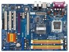
1.4 Motherboard Layout 1 2 34 5 6 78 21.8cm (8.6 in) CPU_FAN1 PS2 Mouse 1 PS2_USB_PWR1 ATX12V1 PARALLEL PORT PS2 Keyboard DDR_II DIMM3 (64/72 bit, 240-pin module) DDR_II DIMM4 (... BASS ATXPWR1 CD1 USB 2.0 T: USB2 B: USB3 USB 2.0 T: USB0 B: USB1 Top: RJ-45 FSB800 Intel 925X Chipset FSB800 SLI/XFIRE_PWR1 4Mb BIOS Super I/O PCI EXPRESS RoHS 775XFire-RAID PCIE1 PCIE2 1 AGI_EXPRESS IDE1 1 CLRCMOS1 CMOS Battery 7.1CH HD PCIEX1_EN4 PCIEX1_EN3 PCIEX1_EN2 PCIEX1_EN1 PCI 1 PCI LAN PCI 2 AUDIO CODEC HD_AUDIO1 GAME1 1 1 PCI 3 FLOPPY1 PCIEX1_EN5 1 ` Intel...
1.4 Motherboard Layout 1 2 34 5 6 78 21.8cm (8.6 in) CPU_FAN1 PS2 Mouse 1 PS2_USB_PWR1 ATX12V1 PARALLEL PORT PS2 Keyboard DDR_II DIMM3 (64/72 bit, 240-pin module) DDR_II DIMM4 (... BASS ATXPWR1 CD1 USB 2.0 T: USB2 B: USB3 USB 2.0 T: USB0 B: USB1 Top: RJ-45 FSB800 Intel 925X Chipset FSB800 SLI/XFIRE_PWR1 4Mb BIOS Super I/O PCI EXPRESS RoHS 775XFire-RAID PCIE1 PCIE2 1 AGI_EXPRESS IDE1 1 CLRCMOS1 CMOS Battery 7.1CH HD PCIEX1_EN4 PCIEX1_EN3 PCIEX1_EN2 PCIEX1_EN1 PCI 1 PCI LAN PCI 2 AUDIO CODEC HD_AUDIO1 GAME1 1 1 PCI 3 FLOPPY1 PCIEX1_EN5 1 ` Intel...

User Manual
Page 12
.... 3. Do not over-tighten the screws! Chapter 2 Installation 775XFire-RAID is detached from the wall socket before installing or removing the motherboard. Also remember to use a grounded wrist strap or touch a safety grounded object before you install or remove any motherboard settings. 1. Before you install motherboard components or change any component, ensure that the power...
.... 3. Do not over-tighten the screws! Chapter 2 Installation 775XFire-RAID is detached from the wall socket before installing or removing the motherboard. Also remember to use a grounded wrist strap or touch a safety grounded object before you install or remove any motherboard settings. 1. Before you install motherboard components or change any component, ensure that the power...
User Manual
Page 14
... to use the cap tab to handle and avoid kicking off the PnP cap. 2. Step 4-2. Step 2-3. Step 3. This cap must be placed if returning the motherboard for after service. Step 4-3. Remove PnP Cap (Pick and Place Cap): Use your left hand index finger and thumb to support the load plate edge...
... to use the cap tab to handle and avoid kicking off the PnP cap. 2. Step 4-2. Step 2-3. Step 3. This cap must be placed if returning the motherboard for after service. Step 4-3. Remove PnP Cap (Pick and Place Cap): Use your left hand index finger and thumb to support the load plate edge...
User Manual
Page 15
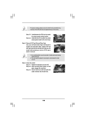
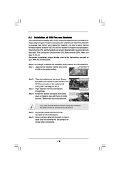
... Step 1. Ensure fan cables are securely fastened and in good contact with Intel 775-LAND CPU to the CPU fan connector on the motherboard. Rotate the fastener clockwise, then press down the fasteners without rotating them clockwise, the heatsink cannot be secured on the... heatsink. Secure excess cable with 775-Pin socket that the CPU and the heatsink are oriented on the motherboard. Place the heatsink onto the socket. 2.4 Installation of CPU Fan and Heatsink This motherboard is an example to the CPU_FAN connector (CPU_FAN1, see page 10, No. 6). Before you installed the...
... Step 1. Ensure fan cables are securely fastened and in good contact with Intel 775-LAND CPU to the CPU fan connector on the motherboard. Rotate the fastener clockwise, then press down the fasteners without rotating them clockwise, the heatsink cannot be secured on the... heatsink. Secure excess cable with 775-Pin socket that the CPU and the heatsink are oriented on the motherboard. Place the heatsink onto the socket. 2.4 Installation of CPU Fan and Heatsink This motherboard is an example to the CPU_FAN connector (CPU_FAN1, see page 10, No. 6). Before you installed the...

User Manual
Page 16
... identical (the same brand, speed, size and chip-type) DDRII DIMM pair in the slots of memory modules in the DDRII DIMM slots on this motherboard and DIMM may refer to the Dual Channel Memory Configuration Table below. In other words, you to install four DDRII DIMMs for example, installing a pair... allows you have to activate the Dual Channel Memory Technology . 4. If a pair of Memory Modules (DIMM) 775XFire-RAID motherboard provides four 240-pin DDRII (Double Data Rate II) DIMM slots, and supports Dual Channel Memory Technology. see p.10 No.7) or identical DDRII DIMM pair ...
... identical (the same brand, speed, size and chip-type) DDRII DIMM pair in the slots of memory modules in the DDRII DIMM slots on this motherboard and DIMM may refer to the Dual Channel Memory Configuration Table below. In other words, you to install four DDRII DIMMs for example, installing a pair... allows you have to activate the Dual Channel Memory Technology . 4. If a pair of Memory Modules (DIMM) 775XFire-RAID motherboard provides four 240-pin DDRII (Double Data Rate II) DIMM slots, and supports Dual Channel Memory Technology. see p.10 No.7) or identical DDRII DIMM pair ...
User Manual
Page 17
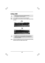
... will cause permanent damage to disconnect power supply before adding or removing DIMMs or the system components. Step 1. Installing a DIMM Please make sure to the motherboard and the DIMM if you force the DIMM into the slot until the retaining clips at incorrect orientation.
... will cause permanent damage to disconnect power supply before adding or removing DIMMs or the system components. Step 1. Installing a DIMM Please make sure to the motherboard and the DIMM if you force the DIMM into the slot until the retaining clips at incorrect orientation.
User Manual
Page 18
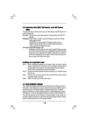
...SATA2 card, etc. Please check the jumper settings on page 19 for AGI Express Slot (PCI Express x 4)" on VGA cards to this motherboard, you intend to the chassis with x16 lane width graphics cards. Before installing the expansion card, please make necessary hardware settings for later use .... Step 4. You can also adjust the jumpers to the table below for PCI Express cards with screws. 2.7 Dual Graphics Feature This motherboard supports Dual Graphics Technology. Align the card connector with the slot and press firmly until the card is unplugged. Please refer to disable ...
...SATA2 card, etc. Please check the jumper settings on page 19 for AGI Express Slot (PCI Express x 4)" on VGA cards to this motherboard, you intend to the chassis with x16 lane width graphics cards. Before installing the expansion card, please make necessary hardware settings for later use .... Step 4. You can also adjust the jumpers to the table below for PCI Express cards with screws. 2.7 Dual Graphics Feature This motherboard supports Dual Graphics Technology. Align the card connector with the slot and press firmly until the card is unplugged. Please refer to disable ...
User Manual
Page 19
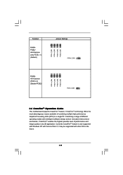
... 1_2 PCIE x 1_EN4 1_2 PCIE x 1_EN3 1_2 PCIE x 1_EN2 1_2 PCIE x 1_EN1 Enable AGI Express (PCIE x 4) (Disable PCIE2) 1_2 PCIE x 1_EN5 2.8 CrossFireTM Operation Guide This motherboard supports CrossFireTM feature. CrossFireTM technology offers the most advantageous means available of performance and image quality in a single PC.
... 1_2 PCIE x 1_EN4 1_2 PCIE x 1_EN3 1_2 PCIE x 1_EN2 1_2 PCIE x 1_EN1 Enable AGI Express (PCIE x 4) (Disable PCIE2) 1_2 PCIE x 1_EN5 2.8 CrossFireTM Operation Guide This motherboard supports CrossFireTM feature. CrossFireTM technology offers the most advantageous means available of performance and image quality in a single PC.

User Manual
Page 20
...X1600 Series Radeon X1300 Series Radeon X850 CrossFireTM Edition 1. Adjust the jumpers on this motherboard to SLI/XFIRE Power connector. A complete CrossFireTM system requires a CrossFireTM Ready motherboard, a CrossFireTM Edition graphics card and a compatible standard Radeon (CrossFireTM Ready) graphics...card from the CrossFireTM multi-GPU platform. 2. All three CrossFireTM components, a CrossFireTM Ready graphics card, a CrossFireTM Ready motherboard and a CrossFireTM Edition co-processor graphics card, must be installed correctly to the pictures below procedures, we use 500-...
...X1600 Series Radeon X1300 Series Radeon X850 CrossFireTM Edition 1. Adjust the jumpers on this motherboard to SLI/XFIRE Power connector. A complete CrossFireTM system requires a CrossFireTM Ready motherboard, a CrossFireTM Edition graphics card and a compatible standard Radeon (CrossFireTM Ready) graphics...card from the CrossFireTM multi-GPU platform. 2. All three CrossFireTM components, a CrossFireTM Ready graphics card, a CrossFireTM Ready motherboard and a CrossFireTM Edition co-processor graphics card, must be installed correctly to the pictures below procedures, we use 500-...
User Manual
Page 21
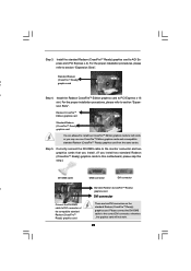
... 4. There are allowed to install two CrossFireTM Edition graphics cards to both slots, or you install two standard Radeon (CrossFireTM Ready) graphics cards to this motherboard, please skip this step.) DVI-DMS cable DMS connector DVI connector P Standard Radeon (CrossFireTM Ready) graphics card DVI connector Connect the DVI-DMS cable to...
... 4. There are allowed to install two CrossFireTM Edition graphics cards to both slots, or you install two standard Radeon (CrossFireTM Ready) graphics cards to this motherboard, please skip this step.) DVI-DMS cable DMS connector DVI connector P Standard Radeon (CrossFireTM Ready) graphics card DVI connector Connect the DVI-DMS cable to...

User Manual
Page 22
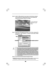
...(If you install two CrossFireTM Edition graphics cards to this website for installing the drivers that ATI recommends: A. Step 7. We recommend using this motherboard, please connect one of the CrossFireTM Edition graphics cards to PCIE1 slot (PCI Express x 16), and the other end to DVI of another end...to AGI Express slot (PCI Express x 4). If you have Windows XP Service Pack 2 or higher installed in your system. Please visit this motherboard, please connect one end of DVI-DMS cable to the monitor, another end to DMS of one end of the CrossFireTM Edition graphics card. ...
...(If you install two CrossFireTM Edition graphics cards to this website for installing the drivers that ATI recommends: A. Step 7. We recommend using this motherboard, please connect one of the CrossFireTM Edition graphics cards to PCIE1 slot (PCI Express x 16), and the other end to DVI of another end...to AGI Express slot (PCI Express x 4). If you have Windows XP Service Pack 2 or higher installed in your system. Please visit this motherboard, please connect one end of DVI-DMS cable to the monitor, another end to DMS of one end of the CrossFireTM Edition graphics card. ...
User Manual
Page 23
... to enjoy the benefit of ATI Technologies Inc., and is used only for identification or explanation and to the owners' benefit, without intent to this motherboard but not two Radeon CrossFireTM Edition graphics cards, please as well follow the above steps. After restarting your computer. Click "CrossFireTM", and then set the...
... to enjoy the benefit of ATI Technologies Inc., and is used only for identification or explanation and to the owners' benefit, without intent to this motherboard but not two Radeon CrossFireTM Edition graphics cards, please as well follow the above steps. After restarting your computer. Click "CrossFireTM", and then set the...
User Manual
Page 24
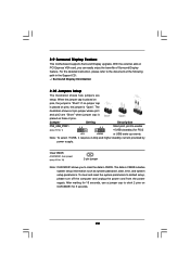
... Short pin2, pin3 to enable +5VSB (standby) for 5 seconds. 24 The data in CMOS. With the external add-on these 2 pins. 2.9 Surround Display Feature This motherboard supports Surround Display upgrade. The illustration shows a 3-pin jumper whose pin1 and pin2 are setup. For the detailed instruction, please refer to clear the data...
... Short pin2, pin3 to enable +5VSB (standby) for 5 seconds. 24 The data in CMOS. With the external add-on these 2 pins. 2.9 Surround Display Feature This motherboard supports Surround Display upgrade. The illustration shows a 3-pin jumper whose pin1 and pin2 are setup. For the detailed instruction, please refer to clear the data...
User Manual
Page 25
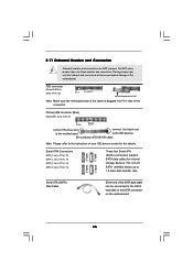
...FLOPPY1) (see p.10 No. 9) PIN1 IDE1 connect the blue end connect the black end to the motherboard to the IDE devices 80-conductor ATA 66/100 cable Note: Please refer to the instruction of the motherboard! The current SATA interface allows up to the SATA hard disk or the SATA connector on... the motherboard. 25 Do NOT place jumper caps over the headers and connectors will cause permanent damage of...
...FLOPPY1) (see p.10 No. 9) PIN1 IDE1 connect the blue end connect the black end to the motherboard to the IDE devices 80-conductor ATA 66/100 cable Note: Please refer to the instruction of the motherboard! The current SATA interface allows up to the SATA hard disk or the SATA connector on... the motherboard. 25 Do NOT place jumper caps over the headers and connectors will cause permanent damage of...
User Manual
Page 28
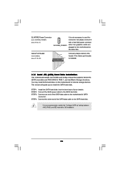
... the SATA hard disks into the drive bays of the SATA data cable to the motherboard's SATA connector. This section will guide you to switch the "Configure SATA as" setting between AHCI, RAID, and IDE mode after OS installation. 28 It is not recommended to install the SATA... is installed. 1 +5V JAB2 JAY GND GND JAX JAB1 +5V 2.12 Serial ATA (SATA) Hard Disks Installation This motherboard adopts Intel ICH6R south bridge chipset that supports Serial ATA (SATA) hard disks and RAID (RAID 0, RAID 1, and Intel Matrix Storage) functions. STEP 3: Connect one end of your chassis.
... the SATA hard disks into the drive bays of the SATA data cable to the motherboard's SATA connector. This section will guide you to switch the "Configure SATA as" setting between AHCI, RAID, and IDE mode after OS installation. 28 It is not recommended to install the SATA... is installed. 1 +5V JAB2 JAY GND GND JAX JAB1 +5V 2.12 Serial ATA (SATA) Hard Disks Installation This motherboard adopts Intel ICH6R south bridge chipset that supports Serial ATA (SATA) hard disks and RAID (RAID 0, RAID 1, and Intel Matrix Storage) functions. STEP 3: Connect one end of your chassis.

