
User Manual
Page 6
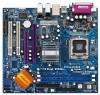
...Form Factor: 9.6-in x 8.6-in, 24.4 cm x 21.8 cm CPU: 775-Pin Socket supporting Intel® Pentium® 4 / Celeron® processor (in 775-land LGA package) Chipsets: North Bridge: Intel® 915GL chipset, FSB @ 800 / 533MHz, supports Hyper-Threading Technology (see CAUTION 1) South Bridge... (10/100 Ethernet), supports Wake-On-LAN Hardware Monitor:CPU temperature sensing, Chassis temperature sensing, CPU overheat shutdown to protect CPU life (ASRock U-COP)(see CAUTION 4), CPU fan tachometer, Chassis fan tachometer, Voltage monitoring: +12V, +5V, +3.3V, Vcore PCI slots: 2 ...
...Form Factor: 9.6-in x 8.6-in, 24.4 cm x 21.8 cm CPU: 775-Pin Socket supporting Intel® Pentium® 4 / Celeron® processor (in 775-land LGA package) Chipsets: North Bridge: Intel® 915GL chipset, FSB @ 800 / 533MHz, supports Hyper-Threading Technology (see CAUTION 1) South Bridge... (10/100 Ethernet), supports Wake-On-LAN Hardware Monitor:CPU temperature sensing, Chassis temperature sensing, CPU overheat shutdown to protect CPU life (ASRock U-COP)(see CAUTION 4), CPU fan tachometer, Chassis fan tachometer, Voltage monitoring: +12V, +5V, +3.3V, Vcore PCI slots: 2 ...

User Manual
Page 11
... 23 22 Top: LINE IN Center: FRONT Bottom: MIC IN CHA_FAN1 COM1 1 775Dual-915GL USB 2.0 T: USB2 B: USB3 USB 2.0 T: USB0 B: USB1 Top: RJ-45 Top: REAR SPK ....4cm (9.6 in) 7 8 9 10 11 12 13 1 PS2_USB_PWR1 Jumper 2 ATX 12V Connector (ATX12V1) 3 775-Pin CPU Socket 4 CPU Fan Connector (CPU_FAN1) 5 184-pin DDR DIMM Slots (DDR1- 2, Dual Channel) 6 Infrared Module Connector (IR1)...23 Front Panel Audio Header (AUDIO1) 24 PCI Slots (PCI1- 2) 25 Clear CMOS Jumper (CLRCMOS1) 26 ASRock Graphics Interface Slot (AGI) 27 AGI Express Slot (PCI Express x 4) 28 Internal Audio Connector: CD1 (...
... 23 22 Top: LINE IN Center: FRONT Bottom: MIC IN CHA_FAN1 COM1 1 775Dual-915GL USB 2.0 T: USB2 B: USB3 USB 2.0 T: USB0 B: USB1 Top: RJ-45 Top: REAR SPK ....4cm (9.6 in) 7 8 9 10 11 12 13 1 PS2_USB_PWR1 Jumper 2 ATX 12V Connector (ATX12V1) 3 775-Pin CPU Socket 4 CPU Fan Connector (CPU_FAN1) 5 184-pin DDR DIMM Slots (DDR1- 2, Dual Channel) 6 Infrared Module Connector (IR1)...23 Front Panel Audio Header (AUDIO1) 24 PCI Slots (PCI1- 2) 25 Clear CMOS Jumper (CLRCMOS1) 26 ASRock Graphics Interface Slot (AGI) 27 AGI Express Slot (PCI Express x 4) 28 Internal Audio Connector: CD1 (...

User Manual
Page 13
.../or components. 13 Whenever you uninstall any motherboard settings. 1. Failure to do so may cause severe damage to the chassis. Chapter 2 Installation 775Dual-915GL is detached from the wall socket before you install motherboard components or change any component, place it on the carpet or the like. Failure to do not touch the...
.../or components. 13 Whenever you uninstall any motherboard settings. 1. Failure to do so may cause severe damage to the chassis. Chapter 2 Installation 775Dual-915GL is detached from the wall socket before you install motherboard components or change any component, place it on the carpet or the like. Failure to do not touch the...

User Manual
Page 14
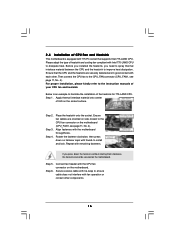
... orientation key notch orientation key notch Pin1 alignment key alignment key 775-LAND CPU 775-Pin Socket 14 black line black line Open the socket: Step 1-1. Hold the CPU by depressing down and out on the socket. Step 2. Orient the CPU with black lines. Do not force to clear retention tab.... the two orientation key notches. 2.3 CPU Installation For the installation of Intel 775-LAND CPU, please follow the steps below. 775-Pin Socket Overview Before you insert the 775-LAND CPU into the socket if above situation is any bent pin on the hook to insert the CPU into the...
... orientation key notch orientation key notch Pin1 alignment key alignment key 775-LAND CPU 775-Pin Socket 14 black line black line Open the socket: Step 1-1. Hold the CPU by depressing down and out on the socket. Step 2. Orient the CPU with black lines. Do not force to clear retention tab.... the two orientation key notches. 2.3 CPU Installation For the installation of Intel 775-LAND CPU, please follow the steps below. 775-Pin Socket Overview Before you insert the 775-LAND CPU into the socket if above situation is any bent pin on the hook to insert the CPU into the...
User Manual
Page 15
... the cap tab to handle and avoid kicking off the PnP cap. Close the socket: Step 4-1. Step 3. Rotate the load plate onto the IHS. Secure load lever with the two alignment keys of... the socket. For proper inserting, please ensure to match the two orientation key notches of the CPU with ...load plate tab under retention tab of load lever. 15 Carefully place the CPU into the socket by using a purely vertical motion. Remove PnP Cap (Pick and Place Cap): Use your left hand index finger...
... the cap tab to handle and avoid kicking off the PnP cap. Close the socket: Step 4-1. Step 3. Rotate the load plate onto the IHS. Secure load lever with the two alignment keys of... the socket. For proper inserting, please ensure to match the two orientation key notches of the CPU with ...load plate tab under retention tab of load lever. 15 Carefully place the CPU into the socket by using a purely vertical motion. Remove PnP Cap (Pick and Place Cap): Use your left hand index finger...
User Manual
Page 16
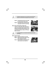
Before you installed the heatsink, you press down on the socket surface. Then connect the CPU fan to the CPU_FAN connector (CPU_FAN1, see page 11, No. 4). For proper installation, please kindly refer to the instruction manuals ... of your CPU fan and heatsink. Please adopt the type of heatsink and cooling fan compliant with remaining fasteners. Step 1. Place the heatsink onto the socket. Connect fan header with 775-Pin socket that the CPU and the heatsink are oriented on side closest to the CPU fan connector on the motherboard.
Before you installed the heatsink, you press down on the socket surface. Then connect the CPU fan to the CPU_FAN connector (CPU_FAN1, see page 11, No. 4). For proper installation, please kindly refer to the instruction manuals ... of your CPU fan and heatsink. Please adopt the type of heatsink and cooling fan compliant with remaining fasteners. Step 1. Place the heatsink onto the socket. Connect fan header with 775-Pin socket that the CPU and the heatsink are oriented on side closest to the CPU fan connector on the motherboard.

User Manual
Page 39
...install the necessary drivers to your dealer for more information. 4.2 Support CD Information The Support CD that came with Intel LGA 775 socket, which is enabled in the motherboard's Support CD through this Live Demo in your CD-ROM drive. Because motherboard settings and ...following path: ..\ MPEGAV \ LGA775INST.DAT 4.2.5 Contact Information If you start the installation of CPU and motherboard damages caused by improper handling, ASRock sincerely presents you can run Microsoft® Media Player® to play the file. Refer to activate the devices. 4.2.3 Utilities Menu The...
...install the necessary drivers to your dealer for more information. 4.2 Support CD Information The Support CD that came with Intel LGA 775 socket, which is enabled in the motherboard's Support CD through this Live Demo in your CD-ROM drive. Because motherboard settings and ...following path: ..\ MPEGAV \ LGA775INST.DAT 4.2.5 Contact Information If you start the installation of CPU and motherboard damages caused by improper handling, ASRock sincerely presents you can run Microsoft® Media Player® to play the file. Refer to activate the devices. 4.2.3 Utilities Menu The...