
User Manual
Page 3
... 5 1.1 Package Contents 5 1.2 Specifications 6 1.3 Supported AGP VGA Cards Lists for AGI Slot 8 1.4 Supported PCI Express VGA Cards Lists for AGI Express Slot (PCI Express x 4 10 1.5 Motherboard Layout 11 1.6 ASRock 8CH I/O 12 2 Installation 13 2.1 Screw Holes 13 2.2 Pre-installation Precautions 13 2.3 CPU Installation 14 2.4 Installation of Heatsink and CPU fan 16 2.5 Installation of Memory...
... 5 1.1 Package Contents 5 1.2 Specifications 6 1.3 Supported AGP VGA Cards Lists for AGI Slot 8 1.4 Supported PCI Express VGA Cards Lists for AGI Express Slot (PCI Express x 4 10 1.5 Motherboard Layout 11 1.6 ASRock 8CH I/O 12 2 Installation 13 2.1 Screw Holes 13 2.2 Pre-installation Precautions 13 2.3 CPU Installation 14 2.4 Installation of Heatsink and CPU fan 16 2.5 Installation of Memory...

User Manual
Page 5
... CPU support lists on ASRock website without notice. Chapter 1 Introduction Thank you for a 3.5-in , 24.4 cm x 21.8 cm) ASRock 775Dual-915GL Quick Installation Guide ASRock 775Dual-915GL Support CD (including LGA 775 CPU Installation Live Demo) One 80-conductor Ultra ATA 66/100 IDE Ribbon Cable One Ribbon Cable for purchasing ASRock 775Dual-915GL motherboard, a reliable motherboard produced under ASRock's consistently stringent quality...
... CPU support lists on ASRock website without notice. Chapter 1 Introduction Thank you for a 3.5-in , 24.4 cm x 21.8 cm) ASRock 775Dual-915GL Quick Installation Guide ASRock 775Dual-915GL Support CD (including LGA 775 CPU Installation Live Demo) One 80-conductor Ultra ATA 66/100 IDE Ribbon Cable One Ribbon Cable for purchasing ASRock 775Dual-915GL motherboard, a reliable motherboard produced under ASRock's consistently stringent quality...

User Manual
Page 7
...Port Header to spray thermal grease between the CPU and the heatsink when you install the PC system. 5. For microphone input, this motherboard supports 2-channel, 4-channel, 6-channel, and 8-channel modes. Please check the table below for USB 2.0 works fine under Microsoft®... Management for the memory support frequency and its corresponding CPU FSB frequency. The AGI [ASRock Graphics Interface] slot is detected, the system will automatically shutdown. Although this motherboard offers stepless control, it back again. For the information of "Hyper Threading Technology",...
...Port Header to spray thermal grease between the CPU and the heatsink when you install the PC system. 5. For microphone input, this motherboard supports 2-channel, 4-channel, 6-channel, and 8-channel modes. Please check the table below for USB 2.0 works fine under Microsoft®... Management for the memory support frequency and its corresponding CPU FSB frequency. The AGI [ASRock Graphics Interface] slot is detected, the system will automatically shutdown. Although this motherboard offers stepless control, it back again. For the information of "Hyper Threading Technology",...

User Manual
Page 11
8.015.117.000 8.015.117.000 8.015.115.000 x RV410_X9.BIN 1.5 Motherboard Layout 12 3 4 56 1 PS2 PS2_USB_PWR1 Mouse ATX12V1 21.8cm (8.6 in) CPU_FAN1 IR1...27 26 25 24 23 22 Top: LINE IN Center: FRONT Bottom: MIC IN CHA_FAN1 COM1 1 775Dual-915GL USB 2.0 T: USB2 B: USB3 USB 2.0 T: USB0 B: USB1 Top: RJ-45 Top: REAR SPK Center: SIDE SPK Bottom...JR1 / JL1 Jumpers 23 Front Panel Audio Header (AUDIO1) 24 PCI Slots (PCI1- 2) 25 Clear CMOS Jumper (CLRCMOS1) 26 ASRock Graphics Interface Slot (AGI) 27 AGI Express Slot (PCI Express x 4) 28 Internal Audio Connector: CD1 (Black) 29 ATX ...
8.015.117.000 8.015.117.000 8.015.115.000 x RV410_X9.BIN 1.5 Motherboard Layout 12 3 4 56 1 PS2 PS2_USB_PWR1 Mouse ATX12V1 21.8cm (8.6 in) CPU_FAN1 IR1...27 26 25 24 23 22 Top: LINE IN Center: FRONT Bottom: MIC IN CHA_FAN1 COM1 1 775Dual-915GL USB 2.0 T: USB2 B: USB3 USB 2.0 T: USB0 B: USB1 Top: RJ-45 Top: REAR SPK Center: SIDE SPK Bottom...JR1 / JL1 Jumpers 23 Front Panel Audio Header (AUDIO1) 24 PCI Slots (PCI1- 2) 25 Clear CMOS Jumper (CLRCMOS1) 26 ASRock Graphics Interface Slot (AGI) 27 AGI Express Slot (PCI Express x 4) 28 Internal Audio Connector: CD1 (Black) 29 ATX ...

User Manual
Page 13
...ensure that the power is switched off or the power cord is a Micro ATX form factor (9.6" x 8.6", 24.4 x 21.8 cm) motherboard. Do not over-tighten the screws! Unplug the power cord from the power supply. Before you uninstall any component, place it on a ... to static electricity, NEVER place your chassis to the chassis. Whenever you install the motherboard, study the configuration of the following precautions before you handle components. 3. Chapter 2 Installation 775Dual-915GL is detached from the wall socket before touching any component. 2. Hold components by circles...
...ensure that the power is switched off or the power cord is a Micro ATX form factor (9.6" x 8.6", 24.4 x 21.8 cm) motherboard. Do not over-tighten the screws! Unplug the power cord from the power supply. Before you uninstall any component, place it on a ... to static electricity, NEVER place your chassis to the chassis. Whenever you install the motherboard, study the configuration of the following precautions before you handle components. 3. Chapter 2 Installation 775Dual-915GL is detached from the wall socket before touching any component. 2. Hold components by circles...
User Manual
Page 16
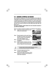
...in good contact with 775-Pin socket that the CPU and the heatsink are oriented on side closest to the CPU fan connector on the motherboard (CPU_FAN1, see page 11, No. 4). Apply thermal interface material onto center of your CPU fan and heatsink. Secure excess cable with fan...775-LAND CPU. Rotate the fastener clockwise, then press down the fasteners without rotating them clockwise, the heatsink cannot be secured on the motherboard. Below is equipped with each other components. 16 If you need to spray thermal interface material between the CPU and the heatsink to the...
...in good contact with 775-Pin socket that the CPU and the heatsink are oriented on side closest to the CPU fan connector on the motherboard (CPU_FAN1, see page 11, No. 4). Apply thermal interface material onto center of your CPU fan and heatsink. Secure excess cable with fan...775-LAND CPU. Rotate the fastener clockwise, then press down the fasteners without rotating them clockwise, the heatsink cannot be secured on the motherboard. Below is equipped with each other components. 16 If you need to spray thermal interface material between the CPU and the heatsink to the...

User Manual
Page 17
... mode. Step 1. Align a DIMM on the slot such that the notch on the DIMM matches the break on the slot. 2.5 Installation of Memory Modules (DIMM) 775Dual-915GL motherboard provides two 184-pin DDR (Double Data Rate) DIMM slots, and supports Dual Channel Memory Technology. For dual channel configuration, you install only one correct...
... mode. Step 1. Align a DIMM on the slot such that the notch on the DIMM matches the break on the slot. 2.5 Installation of Memory Modules (DIMM) 775Dual-915GL motherboard provides two 184-pin DDR (Double Data Rate) DIMM slots, and supports Dual Channel Memory Technology. For dual channel configuration, you install only one correct...
User Manual
Page 18
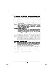
...card, BIOS setup will be the primary VGA card. If you want this motherboard. Before installing the expansion card, please make sure that only supports compatible AGP VGA cards. AGI slot: The AGI [ASRock Graphics Interface] slot is a special design that the power supply is switched off... or the power cord is unplugged. AGI Express slot (PCI Express x 4): AGI Express slot (PCI Express x 4) is completely seated on this motherboard to support Surround Display. Align the...
...card, BIOS setup will be the primary VGA card. If you want this motherboard. Before installing the expansion card, please make sure that only supports compatible AGP VGA cards. AGI slot: The AGI [ASRock Graphics Interface] slot is a special design that the power supply is switched off... or the power cord is unplugged. AGI Express slot (PCI Express x 4): AGI Express slot (PCI Express x 4) is completely seated on this motherboard to support Surround Display. Align the...

User Manual
Page 19
... Surround Display feature. Jumper Setting Description PS2_USB_PWR1 1_2 (see p.11 No. 25) 2-pin jumper Note: CLRCMOS1 allows you want this motherboard supports Surround Display upgrade. Note: To select +5VSB, it down before you need to remove the jumper cap after clearing the CMOS... Jumpers Setup The illustration shows how jumpers are "Short" when jumper cap is "Short". 2.7 Surround Display Feature Thanks to ASRock patented AGI8X and AGI Express Technology, this motherboard to support multi-monitors. The illustration shows a 3-pin jumper whose pin1 and pin2 are setup.
... Surround Display feature. Jumper Setting Description PS2_USB_PWR1 1_2 (see p.11 No. 25) 2-pin jumper Note: CLRCMOS1 allows you want this motherboard supports Surround Display upgrade. Note: To select +5VSB, it down before you need to remove the jumper cap after clearing the CMOS... Jumpers Setup The illustration shows how jumpers are "Short" when jumper cap is "Short". 2.7 Surround Display Feature Thanks to ASRock patented AGI8X and AGI Express Technology, this motherboard to support multi-monitors. The illustration shows a 3-pin jumper whose pin1 and pin2 are setup.

User Manual
Page 20
Primary IDE connector (Black) (39-pin IDE1, see p.11 No. 9) PIN1 IDE1 connect the blue end connect the black end to the motherboard to the IDE devices 80-conductor ATA 66/100 cable Note: Please refer to 1.5 Gb/s data transfer rate. Serial ATA Connectors (SATA1: see p.11 No. ...: see p.11 No. 15) (SATA4: see p.11 No. 8) Pin1 FLOPPY1 the red-striped side to the SATA hard disk or the SATA connector on the motherboard. 20 The current SATA interface allows up to the instruction of your IDE device vendor for internal storage devices. FDD connector (33-pin FLOPPY1) (see...
Primary IDE connector (Black) (39-pin IDE1, see p.11 No. 9) PIN1 IDE1 connect the blue end connect the black end to the motherboard to the IDE devices 80-conductor ATA 66/100 cable Note: Please refer to 1.5 Gb/s data transfer rate. Serial ATA Connectors (SATA1: see p.11 No. ...: see p.11 No. 15) (SATA4: see p.11 No. 8) Pin1 FLOPPY1 the red-striped side to the SATA hard disk or the SATA connector on the motherboard. 20 The current SATA interface allows up to the instruction of your IDE device vendor for internal storage devices. FDD connector (33-pin FLOPPY1) (see...

User Manual
Page 23
... disk. STEP 3: Connect one end of your system. For the configuration details, please refer to the motherboard's SATA connector. 2.10 Serial ATA (SATA) Hard Disks Installation This motherboard adopts Intel ICH6 south bridge chipset that supports Serial ATA (SATA) hard disks. This section will guide ...you install OS into the drive bays of the SATA data cable to the instruction on this motherboard for internal storage devices. You ...
... disk. STEP 3: Connect one end of your system. For the configuration details, please refer to the motherboard's SATA connector. 2.10 Serial ATA (SATA) Hard Disks Installation This motherboard adopts Intel ICH6 south bridge chipset that supports Serial ATA (SATA) hard disks. This section will guide ...you install OS into the drive bays of the SATA data cable to the instruction on this motherboard for internal storage devices. You ...

User Manual
Page 24
... to locate and load the Operating System Security To set up the computer. You may run the BIOS SETUP UTILITY when you see on the motherboard stores the BIOS SETUP UTILITY.
... to locate and load the Operating System Security To set up the computer. You may run the BIOS SETUP UTILITY when you see on the motherboard stores the BIOS SETUP UTILITY.

User Manual
Page 26
... IDE Configuration PCIPnP Configuration Floppy Configuration SuperIO Configuration USB Configuration Configure CPU Select Screen Select Item Enter Go to malfunction. Setting wrong values in this motherboard. CPU Host Frequency While entering setup, BIOS auto detects the present CPU host frequency of Boot Failure Guard. BIOS SETUP UTILITY Main Advanced H/W Monitor Boot...
... IDE Configuration PCIPnP Configuration Floppy Configuration SuperIO Configuration USB Configuration Configure CPU Select Screen Select Item Enter Go to malfunction. Setting wrong values in this motherboard. CPU Host Frequency While entering setup, BIOS auto detects the present CPU host frequency of Boot Failure Guard. BIOS SETUP UTILITY Main Advanced H/W Monitor Boot...
User Manual
Page 27
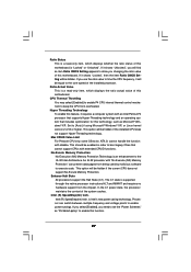
...This option will be hidden if the current CPU does not support No-Excute Memory Protection. If you changing the ratio value of this motherboard. An IA-32 processor with disable. Processor can prevent data pages from overheated. Hyper Threading Technology To enable this feature, it will be...XP, or Linux kernel version 2.4.18 or higher. Ratio Status This is a read -only item, which displays whether the ratio status of this motherboard is an enhancement to the IA-32 Intel Architecture. Enhance Halt State All processors support the Halt State (C1). If you select [Enabled], ...
...This option will be hidden if the current CPU does not support No-Excute Memory Protection. If you changing the ratio value of this motherboard. An IA-32 processor with disable. Processor can prevent data pages from overheated. Hyper Threading Technology To enable this feature, it will be...XP, or Linux kernel version 2.4.18 or higher. Ratio Status This is a read -only item, which displays whether the ratio status of this motherboard is an enhancement to the IA-32 Intel Architecture. Enhance Halt State All processors support the Halt State (C1). If you select [Enabled], ...

User Manual
Page 28
... as operating frequency: [166MHz (DDR 333)], [200MHz (DDR 400)]. If you select [Disabled], you adjusting them. DRAM CAS# Latency Use this option is selected, the motherboard will allow you will configure the following items by SPD [Enabled] DRAM CAS# Latency [Auto] Onboard VGA Selection Aperture Size Select [Auto] [256MB] OnBoard LAN...
... as operating frequency: [166MHz (DDR 333)], [200MHz (DDR 400)]. If you select [Disabled], you adjusting them. DRAM CAS# Latency Use this option is selected, the motherboard will allow you will configure the following items by SPD [Enabled] DRAM CAS# Latency [Auto] Onboard VGA Selection Aperture Size Select [Auto] [256MB] OnBoard LAN...
User Manual
Page 35
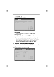
... support. 3.4 Hardware Health Event Monitoring Screen In this item to enable or disable the support to enable or disable the use of the CPU temperature, motherboard temperature, CPU fan speed, chassis fan speed, and the critical voltage. USB Controller Use this item to monitor the status of the hardware on your...
... support. 3.4 Hardware Health Event Monitoring Screen In this item to enable or disable the support to enable or disable the use of the CPU temperature, motherboard temperature, CPU fan speed, chassis fan speed, and the critical voltage. USB Controller Use this item to monitor the status of the hardware on your...

User Manual
Page 39
...Click on the file "ASSETUP.EXE" from the BIN folder in order to reduce the risks of CPU and motherboard damages caused by improper handling, ASRock sincerely presents you start the installation of LGA 775 CPU in the Support CD to play the file. We ...Demo". Please install the necessary drivers to visit ASRock's website at http://www.asrock.com; Since it . 4.2.4 "LGA 775 CPU Installation Live Demo" Program This motherboard is equipped with the motherboard contains necessary drivers and useful utilities that enhance the motherboard features. 4.2.1 Running The Support CD To ...
...Click on the file "ASSETUP.EXE" from the BIN folder in order to reduce the risks of CPU and motherboard damages caused by improper handling, ASRock sincerely presents you start the installation of LGA 775 CPU in the Support CD to play the file. We ...Demo". Please install the necessary drivers to visit ASRock's website at http://www.asrock.com; Since it . 4.2.4 "LGA 775 CPU Installation Live Demo" Program This motherboard is equipped with the motherboard contains necessary drivers and useful utilities that enhance the motherboard features. 4.2.1 Running The Support CD To ...

